Channell Green Hornet G5N User manual

INSTALLATION INSTRUCTIONS
G5N
channell.com
100%
Made in
USA

Table of Contents
I. Product Introduction ................................................3
II. Tools Recommended .................................................4
III. Installation Kit .........................................................5
IV. Cable Preparation.....................................................5
A. For mid-span access .............................................5
B. For cable ends......................................................6
V. Shield Bond Connector Installation...........................7
VI. Cable Lubrication.....................................................8
VII. Installation of Main Grommet ..................................9
VIII. Branch Cable Grommet Installation ........................10
IX. Bonding and Grounding of Installed Cable ...............1 1
X. Strength Member Tiedowns .....................................12
XI. Splice Tray Preparation............................................12
XII. Slack Storage...........................................................13
XIII. Drop Cable Installation ......................................14-15
XIV. Closing the G5N Enclosure.....................................16
channell.com

I. Product Introduction
The Next Generation Green Hornet has been updated and advanced to
simplify installation and increase capacity. The new design implements
a bottom slack basket and splice trays that can be customized to the
needs of the architecture. The G5N uses Channell’s Universal Splice
Tray to accommodate single fiber splicing, ribbon splicing, Engineered
Tap/PLC splitters, and a 16-port bulkhead. Fully loaded with splice
holders on each of the Universal Splice Trays 144 fibers can be single
spliced inside this closure and 192 fibers if ribbon splicing is performed.
3
All specifications subject to change without notice.
36 Fiber Tray
Ribbon Splice Tray Splitter Tray
24 Fiber Tray

4
All specifications subject to change without notice.
II. Tools Recommended
• Safety glasses
• Gloves
• Other Personal Protective Equipment as required
• Electrician scissors
• Side-angle cutters
• 216 Tool (can wrench)
• Cable knife
• Tape measure
• Rotary Buffer Tube Ringer
• Mid-Span Access Tool
• Cleaning solvent/degreaser
• Splicing equipment
The Next Generation Green Hornet G5 closure is available in two
different base styles.
Option One is the Branch
Base option that has a
Figure-8 hole for main feeder
cables, a single Branch Port
for lateral cables up to .8”
OD and eight Drop Ports for
cables up to .45” OD.
Option Two is the Terminal
base that has a Figure-8 hole
for main feeder cables and
twelve Drop Ports for cables
up to .45” OD.

5
All specifications subject to change without notice.
III. Installation Kit
• 2 – 9”x 5mm transition tubes
• 2 – 99% alcohol wipes
• 8 – 4” black zip ties for trays
• Blue felt for buffer tubes
• ¼”- 20 bolt and washer for bracket installation when needed
• 12 fiber single splice holder
• Three position splitter holder
• Bonding and grounding kit (optional)
IV. Cable Preparation
A. For mid-span access
1. Create a loop in the cable that will allow for ring cuts on both
sides of the loop. The opening of the cable should be 96” total.
2. At the center of the loop remove 4” of sheath from the cable
exposing the buffer tubes and locate the pull strings used to rip
the sheath.
3. If possible, try to locate and center the RO, reverse oscillation,
point of the cable and make this the center of the loop. This will
allow for easier unwrapping of the buffer tubes.
4. Make a ring cut on both sides of the loop 48” from the center of
your loop.

6
All specifications subject to change without notice.
5. Notch the sheath with a pair of electrician scissors where the pull
string is located to help start the cutting of the sheath with the
pull string.
6. Cut the pull strings in half and use each pull string to cut through
the sheath on both sides down to the ring cut made in step 4 and
cut the pull strings cleanly away from the cable.
7. Remove the sheath and any binder cords, aramid yarn, or water-
swellable tape that may be on the buffer tubes.
8. Based on Engineering design, identify which buffer tube will be
used at this time as the feeder and carefully unwrap from the
group using the Reverse-Oscillation Point to assist with counter-
wraps. Separate this buffer tube or ribbon all the way back to the
sheath opening.
9. Utilizing the Reverse-Oscillation Point (or counter-wrap) unwrap
the central strength member, if present, keeping all other buffer
tubes wrapped up neatly.
10. Cut both sides of the central strength member 5” from the
sheath opening. These will be trimmed down during cable
installation.
B. For Cable Ends
1. Measure the cable end to be opened with at least 48” of buffer
tube remaining.
2. Make a ring cut where the sheath will be removed, and the buffer
tubes will be exposed.
3. Remove two inches of sheath from the end of the cable.
4. Notch the sheath where the pull strings are located to assist with
the sheath opening.
5. Pull both pull strings from the end of the cable down to where
the ring cut was made and cleanly cut away the strings at the
sheath opening.
6. Remove the sheath and any binder cords, aramid yarn, or water-
swellable tape that may be present in the cable.
7. If present, unwrap the central strength member from the end
of the cable back to the sheath opening keeping all buffer tubes
cleanly wrapped together.
8. Cut the central strength member 5” from the sheath opening.
This will be trimmed down during cable installation.
7
All specifications subject to change without notice.
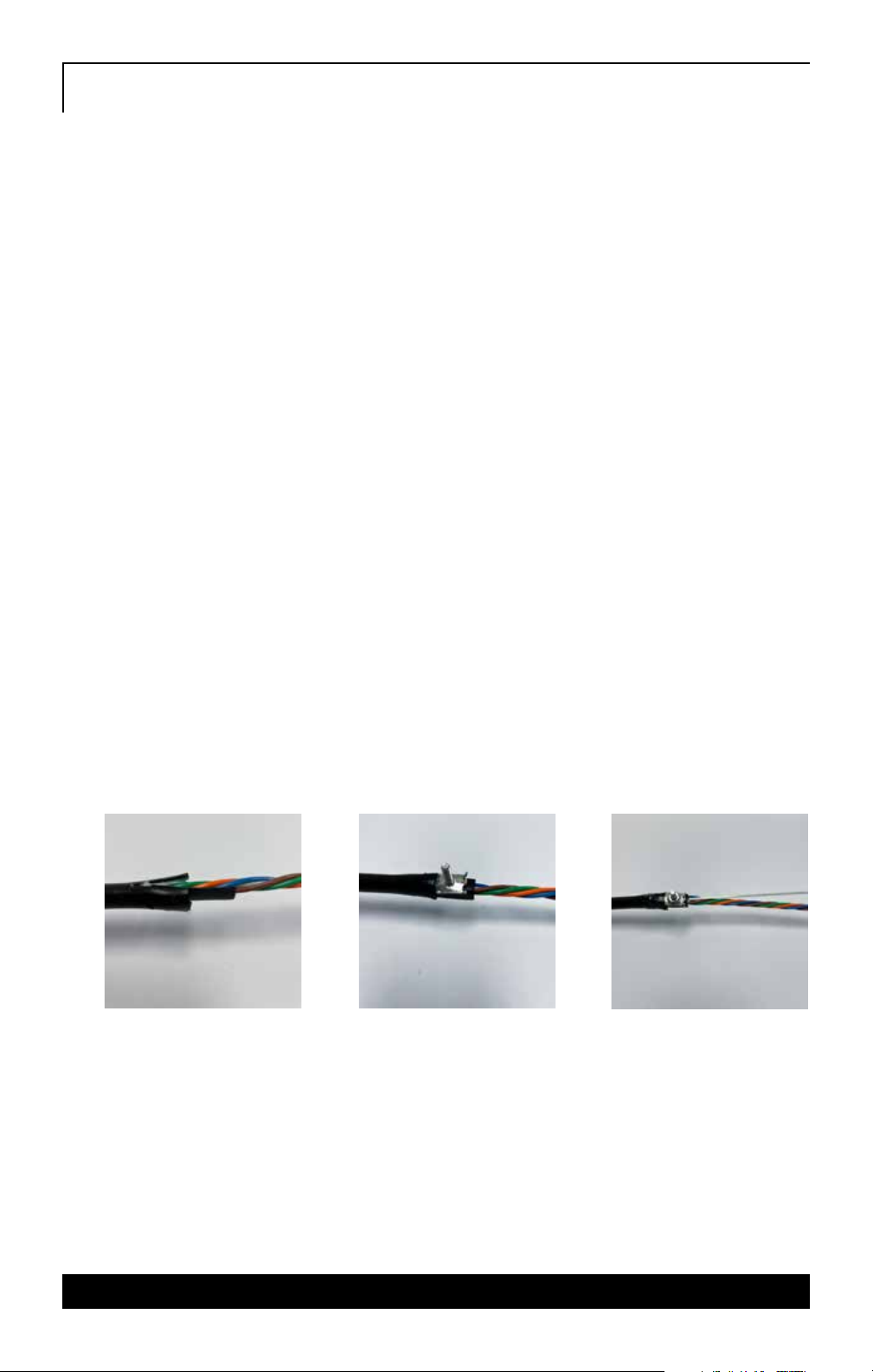
V. Shield Bond Connector Installation
The Shield Bond Connectors are designed to make a stable and low
resistance electrical connection between communications cables of
.80” diameter or less and a conductor such as a strap, wire, or braid.
1. At your ring point, remove outer sheath and cut the armor shield
flush with the cable opening.
2. Using the pull strings or tabbing shears create a 1” (25 mm) slit on
both sides of the sheath, to ease insertion and to avoid buffer tube
damage.
3. When using the Shield Bond Connectors on single-sheath cable,
insert the Pair Saver insulating shoe between the core wrap and the
shield.
4. Insert connector base between shield and buffer tubes until
“connector stops” meet outer sheath. Tap sheath above connector
base to set teeth.
5. Install the top of the shield connector and secure it with one of the
nuts provided. Torque the nut to 35-45 inch-lbs. (4.0-5.2 kgm)
with a company-approved tool
6. The bond braid or other grounding or bonding hardware should be
installed above the first nut and secure it with the additional nut.
Note: Use a company approved tool to achieve the torque requirement specified.
8
All specifications subject to change without notice.
VI. Main Cable/Figure-8 Grommet Selection
If Mid-Span Access, carefully feed the buffer tube(s), with sheath
removed, through the figure-8 shaped port of the enclosure and
assure that no tube is excessively bent. If cable ends, feed the buffer
tube(s) through the appropriate port of the enclosure.
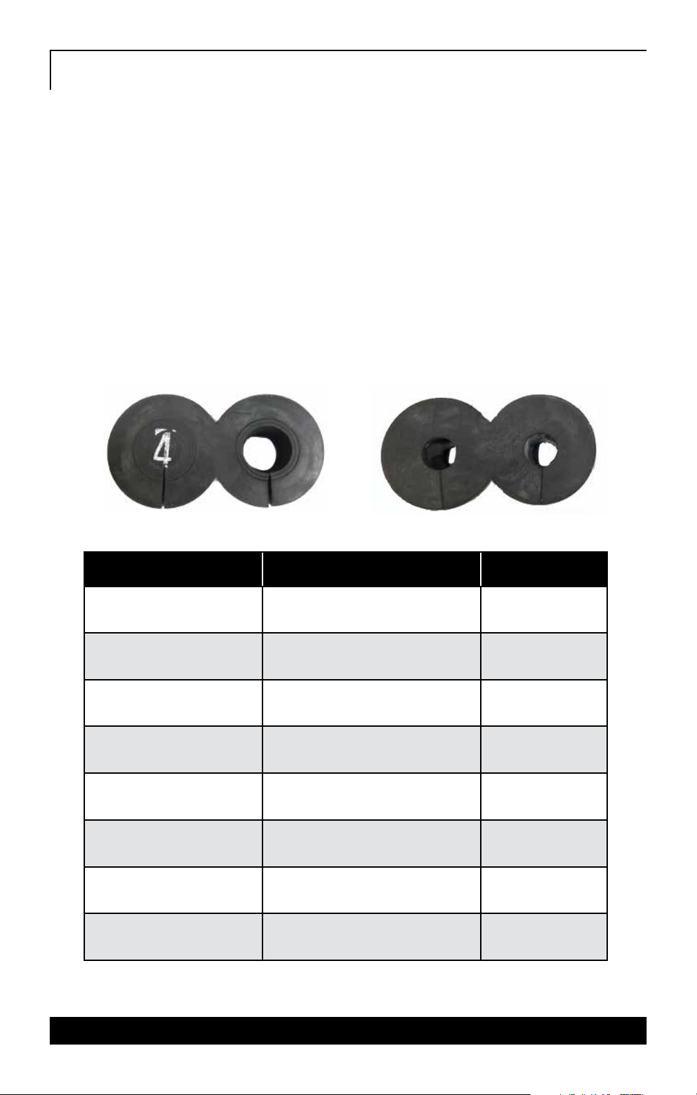
There are two types of Figure-8 grommets that may be included
with the enclosure pinned and serrated. See your local Channell
Salesperson to determine which grommet is best for your application.
Determine the appropriate Figure-8 grommet to install based on cable
diameter. The cable diameter should be within the parameters of the
hole size for the correct grommet.
PART # CABLE SIZE QUANTITY
GR06106407-34 Cable Size .188-.250” 12 per kit
GR06106407-45 Cable Size .250-.313” 12 per kit
GR06106407-56 Cable Size .313-.375” 12 per kit
GR06106407-67 Cable Size .375-.438” 12 per kit
GR06106407-78 Cable Size .438-.500” 12 per kit
GR06106407-89 Cable Size .500-.562” 12 per kit
GR03106407-49 Serrated Grommet, Cable Size .4-.9” 12 per kit
GR03106407-47 Serrated Grommet, Cable Size .4-.7” 12 per kit

9
All specifications subject to change without notice.
Example of Using Correct Amount of Channell Lubrication
*Note-Only Channell provided lubricant in conjunction with the correct
grommet will create an air/watertight seal. Use of any other lubricant will
nullify the sealing integrity of the enclosure and product warranty.
VII. Installation of Main Grommet
**Serrated grommet has rings that will need to be CUT OUT based on the cable
diameter. This is determined with the measuring tape included with this type of
grommet.
1. No electrical tape or other material should be placed on the cable
where it will contact the grommet. Doing so will create a leak.
2. Apply a small amount of Channell lubricant to the entire outside and
vertical slit of the grommet. The surface should appear wet but not
excessively so. The amount of lubricant used directly relates to the
amount of time it will take to create a permanent seal. With the right
amount, the grommet will seal within 10-15 minutes. More time will be
needed if excessive lubricant is used.
3. If armored cable is used and a ground bond is required, it should be
installed after the cable is through the base of the closure but before
the grommet is installed.
4. Place grommet around cable, leaving about 1/2” of sheath above the
grommet if dielectric cable is used. 1 1/2” if armored cable requiring
grounding.
NONE CORRECT AMOUNT TOO MUCH

5. Use steady downward pressure to sink the grommet into the
Figure-8 port. Continue pressure until grommet hits the bottom
stop of the port. The grommet will sit below the surface if seated
properly.
6. Verify that the entire surface of the grommet is level and neither
side of the vertical slit is higher than the other.
7. Wipe off any excess lubricant from the base surface using isopropyl
alcohol wipes included.
8. Attach the central strength member to the CTM and trim off any
excess strength member flush with the top of the clip.
9. Allow to dry before tension is placed on the cable.
VIII. Branch Cable Grommet Installation
GR03106161 Serrated Grommet, Hole Size .4-.8”
**Serrated grommet has rings that will need to be CUT OUT
based on the cable diameter. This is determined with the
measuring tape included with this type of grommet. Same
step as the main grommet
1. No electrical tape or other material should be placed on the cable
where it will contact the grommet. Doing so will create a leak.
2. Apply a small amount of Channell lubricant to the entire outside
and vertical slit of the grommet. The surface should appear wet but
not excessively so. The amount of lubricant used directly relates
to the amount of time it will take to create a permanent seal. With
the right amount, the grommet will seal within 10-15 minutes.
More time will be needed if excessive lubricant is used.
3. Face vertical slit towards the outside of the enclosure.
4. If armored cable is used and a ground bond is required, it should
be installed after the cable is through the base of the closure but
before the grommet is installed.
10
All specifications subject to change without notice.

11
All specifications subject to change without notice.
5. Place grommet around cable, leaving about 1/2” of sheath above
the grommet if dielectric cable is used. 1½” if armored cable
requiring grounding.
6. Use steady downward pressure to sink the grommet into the
Branch port. Continue pressure until grommet hits the bottom
stop of the port. The grommet will sit below the surface if seated
properly.
7. Verify that the entire surface of the grommet is level and neither
side of the vertical slit is higher than the other.
8. Wipe off any excess lubricant from the base surface using
isopropyl alcohol wipes included.
9. Attach the central strength member to the CTM and trim off any
excess strength member flush with the top of the clip.
10. Allow to dry before tension is placed on the cable.
IX. Bonding and Grounding of Installed Cable
1. When armored cable is used and the bond device has been
installed on each cable the cables will need to be strapped to the
Ground Post that is embedded in the base of the G5N.
2. Starting with the cable that is furthest from Ground Post install
the braided ground strap (using an eyelet) to the post of the
ground bond on the cable and secure with the nut provided with
the ground bond.
3. Use one eyelet for each of the cables that are bonded securing
them with the nuts from the ground bond kit.
4. With the last eyelet of the braided strap attach the strap under
the washer and nut of the ground post that is embedded into the
base of the closure.
5. Tighten and secure each nut on every connection to the specific
torque described in the bonding and ground section.

12
All specifications subject to change without notice.
X. Strength Member Tie Down for Main Cable
and Branch Cable
The strength member should be tied down for any cable installed into either the
main, Figure-8 grommet or Branch grommet.
1. In the previous step there was about 5” of strength member
left. At this point, line up the strength member with the top,
inside edge of the strength member holder and cut the strength
member to that length.
2. With a 7/16” nut driver loosen or remove the bolt and washer of
the strength member holder and slide the strength member of
the cable under the washer.
3. Re-tighten the bolt and washer.
XI. Splice Tray Preparation
1. For mid-span access of buffer tube, separate the intended buffer
tube used at this location according to engineering.
2. Secure the buffer tube(s) to the slack basket under the splice
trays with a zip tie.
3. Take the buffer tube(s) needed and route them around the slack
basket and exit out the opposite side from where they came in.
4. Route that tube up to the appropriate splice tray going around
the tray stalk.
5. Using a felt tip marker, make a mark on the buffer tube(s) at the
point of the splice tray before reaching the storage area of the
tray. (About ½” in)
6. Using preferred mid-span access tool, remove all buffer tube
material between marks to expose the fiber.
7. If a tail is being installed, mark the buffer tube at the same point
as would be done for a mid-span access. Use a ringing tool to
remove buffer tube at your mark.
13
All specifications subject to change without notice.
8. Clean and dry all fiber thoroughly before applying the blue felt
padding.
9. Using felt padding provided, wrap a single layer around the buffer
tube just below the point of tube removal. This will prevent the
buffer tube from sliding into or out of the splice tray.
10. With two cable ties (provided) secure the felt wrapped buffer
tube(s) into the tray on both sides.
11. Splice according to engineering design.
12. Wrap all spliced fiber up first and then pass-through fibers from
expressed tubes and then wrap any cut fiber that was not spliced.
13. Place plastic cover on splice tray to protect any fibers that are in
the tray.
XII. Slack Storage
All buffer tubes that are not being used at this location should be
wrapped up neatly in the slack basket below the splice trays. Secure the
wraps of buffer tubes with cable ties.
XIII. Drop Cable Installation
Measure the outside diameter of utilized drop to determine the
correct grommet size.
Note: For flat drop cables, the sealing grommet labeled 3-4
(smallest available) is to be used.
Channell Drop grommets to seal one cable each
Note-Only Channell provided lubricant in conjunction with the
correct grommet will create an air/watertight seal. Use of any other
lubricant will nullify the sealing integrity of the enclosure and
product warranty.
14
All specifications subject to change without notice.
PART # CABLE SIZE QUANTITY
GR06116101-02 Cable Size .062-.125” 12 Cards, 6 grommets per card
GR06116101-34 Cable Size .188-.250” 12 Cards, 6 grommets per card
GR06116101-45 Cable Size .250-.313” 12 Cards, 6 grommets per card
GR06116101-56 Cable Size .313-.375” 12 Cards, 6 grommets per card
GR06116101-67 Cable Size .375-.438” 12 Cards, 6 grommets per card
GR06116101-78 Cable Size .438-.500” 12 Cards, 6 grommets per card

15
All specifications subject to change without notice.
1. Remove the reusable plug from the base in the port where the cable
is to be installed.
2. No electrical tape or other material should be placed on the cable
where it will contact the grommet. Doing so will create a leak.
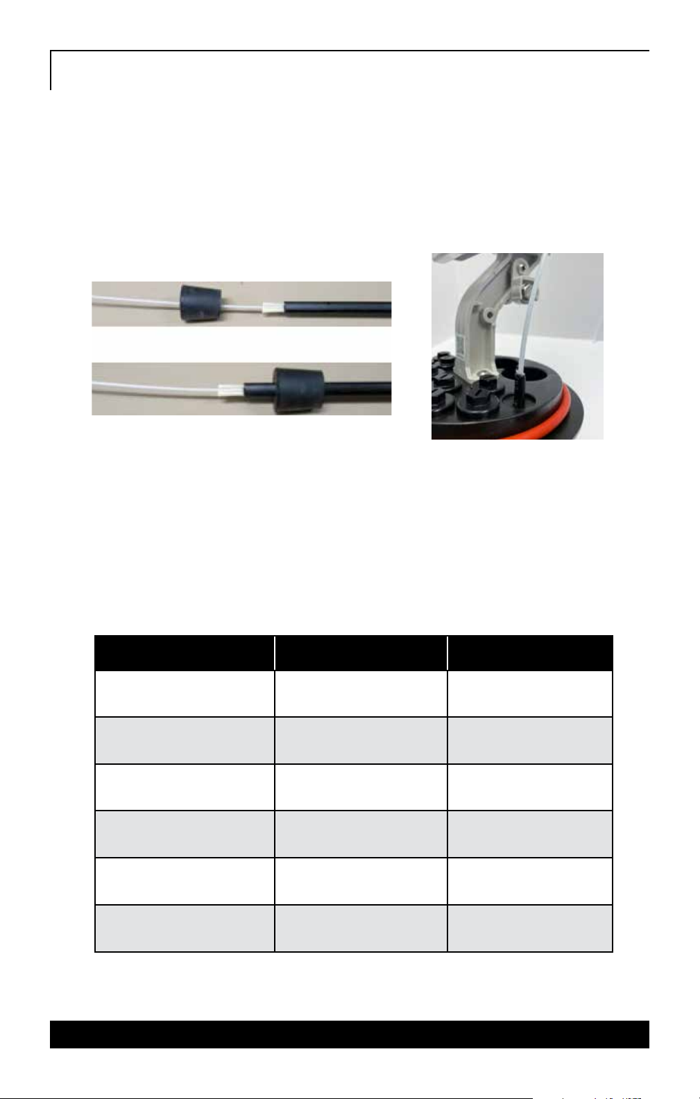
3. If the drop cable being installed has a tracer wire, this wire must be
stripped back so that it is completely outside of the closure after
grommet installation.
4. Sand the excess material left after removing tracer wire.
5. Insert the cable through the base from the outside. Place the sealing
grommet over the end of the cable and slide along the length of the
cable until ½” of sheath is sticking out of the top of the grommet.
6. Lubricate the outside of the sealing grommet with the lubricant
provided and wipe a small amount of the lubricant inside of the drop
port you are installing into to assist with insertion.
7. Insert the drop grommet into the terminal base, as shown.
8. Press firmly down on the top of the grommet until the grommet is
sitting just below the surface of the base. If necessary, use a blunt
tool like a screwdriver to go around the top surface of the grommet
and compress the grommet until it is fully seated.

16
All specifications subject to change without notice.
9. The sealing grommet is properly installed when the top surface of
sealing grommet is sitting slightly below top surface of terminal base.
10. Make sure to remove any excess lubricant from around the base using
an alcohol wipe.
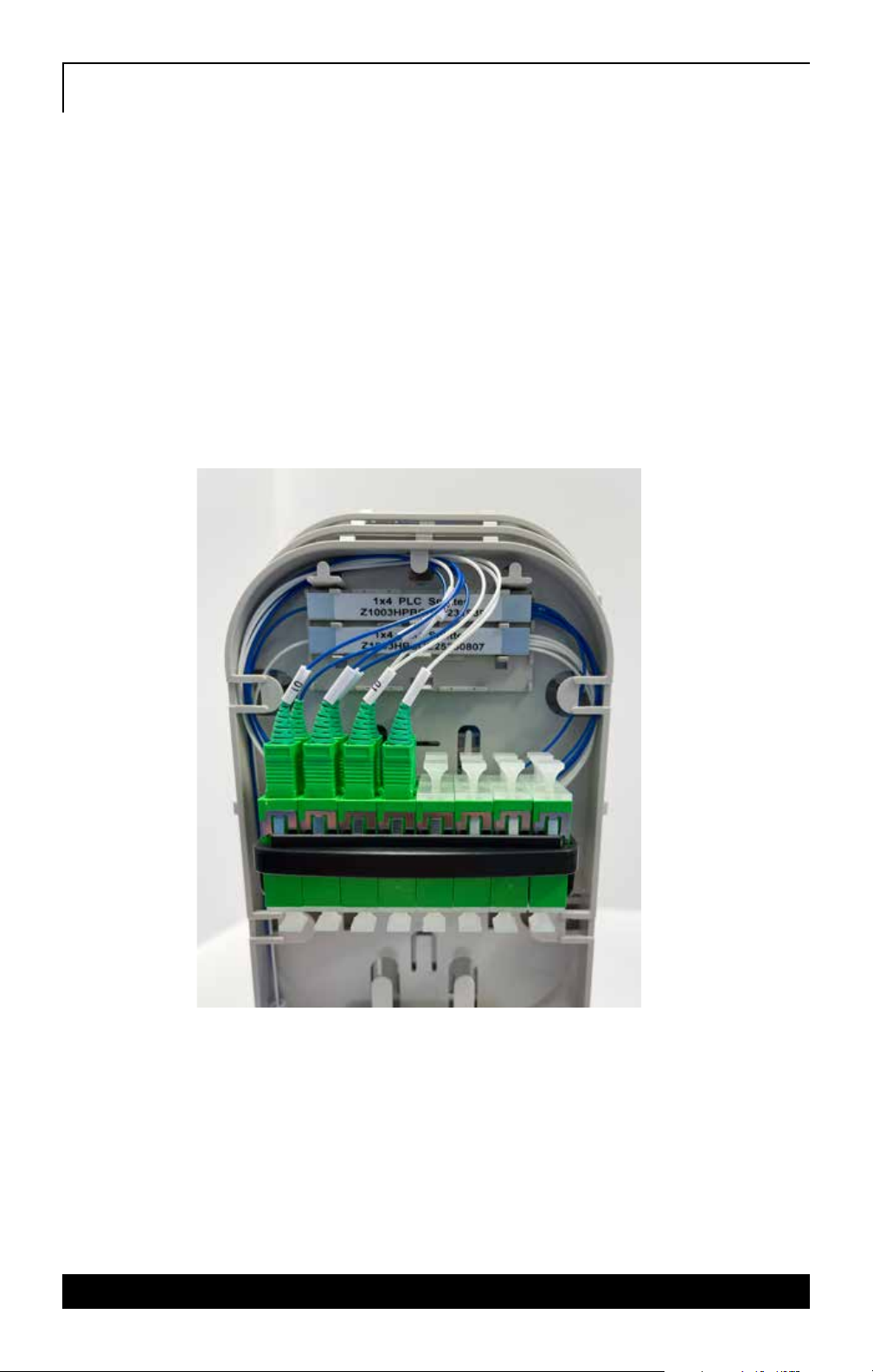
11. Once the drop cable has been installed correctly into the base of the
G5N the fiber or buffer tube can be routed to the appropriate splice
tray or adapter.
12. Remove the clear cover of the splice tray the fiber will be installed
into.
13. Secure the buffer tube or fiber to the splice tray and route around
the tray to the correct length for splicing. If a connector is installed
on the end of the drop cable leave a couple of inches of slack in the
fiber before plugging into the adapter to prevent tension on the
connector and fiber.
14. If splicing a pigtail on the end of the drop utilize one of the splice
trays below the adapter tray.
15. First, clean the connector of the pigtail and plug it into the port
assigned by engineering.
16. Route the pigtail down to the splice tray using one of the 5mm tubes
provided in the set-up kit and splice according to engineering.
17. Install clear cover back on the splice tray to protect all the fibers and
splices.
XIV. Closing the G5N Enclosure
1. Using the orange, Fiber Optic Sticker adhered to the outside of the
dome line up the ¼” hole in the side wall of the base with the sticker
and slide the dome down over the trays and slack basket being careful
not to snag or smash any fiber or buffer tubes inside.
2. Wrap the dome clamp around the edge of where the dome and base
meet.
3. Latch the lock of the clamp and press closed until the clamp is fully
sealed and secure around the dome and base.

WORLDWIDE HEADQUARTERS: Channell Commercial Corporation, Rockwall, TX, United States • Tel 800.423.1863 • Fax 951.296.2322
CANADA: Channell Canada, Inc., Mississauga, ON, Canada • Tel 905.565.1700 • Fax 905.565.8282
EUROPE, MIDDLE EAST, AFRICA: Channell Ltd., Dartford, United Kingdom • Tel 44.1322.312590 • Fax 44.1322.508490
AUSTRALIA, ASIA, PACIFIC RIM: Channell Pty. Ltd., Seven Hills, NSW, Australia • Tel 61.2.8884.4111 • Fax 61.2.8814.8841
www.channell.com
All specifications subject to change without notice. © 2021 Channell Commercial Corporation. All rights reserved.
092821PART NUMBER 0000-00000-00
Table of contents
Popular Enclosure manuals by other brands


Thermaltake
Thermaltake View 91 TG user manual

StarTech.com
StarTech.com RK1219WALHM instruction manual

Hubbell
Hubbell GAI-TRONICS 733-006 manual

Western Digital
Western Digital WDBABV0010ABK - Elements SE Portable Specifications

Salsbury Industries
Salsbury Industries S-61000 Series installation instructions

Icy Box
Icy Box IB-RD3621-C31 manual