Chapman TH200 User manual


Page 2
Contents
Contents............................................................................................................................................................. 2
HSE Information................................................................................................................................................. 3
Important Safety Information ........................................................................................................................... 4
DEFINITIONS .................................................................................................................................................. 4
Safety Information......................................................................................................................................... 4
Transportation Safety.................................................................................................................................... 4
Operating Safety............................................................................................................................................ 4
Description......................................................................................................................................................... 5
Identification.................................................................................................................................................. 5
Implement Decals.......................................................................................................................................... 5
Attachment........................................................................................................................................................ 7
Before Attaching the Machine ...................................................................................................................... 7
Attaching the Machine .................................................................................................................................. 7
Initial Set-up....................................................................................................................................................... 7
Height ............................................................................................................................................................ 7
Initial Test Operation..................................................................................................................................... 8
Operation........................................................................................................................................................... 8
Operation....................................................................................................................................................... 8
Forward Speed............................................................................................................................................... 8
Operating Limits ............................................................................................................................................ 8
Storage........................................................................................................................................................... 9
Troubleshooting................................................................................................................................................. 9
Warranty.......................................................................................................................................................... 10
The Chapman Warranty .............................................................................................................................. 10
Warranty Conditions ................................................................................................................................... 10
Transfer of Warranty................................................................................................................................... 10
THIS MANUAL MUST BE HANDED TO THE OPERATOR BEFORE USE. THE OPERATOR MUST UNDERSTAND FULLY THE
CONTENT OF THIS HANDBOOK BEFORE USING THE MACHINE FOR THE FIRST TIME. OF THE IMPLEMENT IS
RESOLD, THIS MANUAL MUST ACCOMPANY THE MACHINE.
NOTE:
The information contained in this manual is correct at the time of going to press. However, in the course of
development, changes in specification are inevitable. Should you find the information given differs from your
machine, please contact Chapman Machinery Ltd direct for advice. Use only Chapman Genuine Service Parts on
Chapman Machinery and Machines.

Page 3
HSE Information
Safe use of all-terrain vehicles (ATVs) in agriculture and forestry –AIS Sheet 33
Introduction
This information sheet gives advice on the safe use of ATVs. It covers
the two main types used in off-road working in agriculture and
forestry, which are:
•sit-astride ATV / sit-in machines
•side-by-side mini-utility vehicles,
The Full HSE information sheet can be found here or using the QR
Code at the bottom of the article:
https://www.hse.gov.uk/pubns/ais33.pdf and must be read prior to
any ATV/UTV use. Below are related extracts to trailed machinery.
REMEMBER - GET PROPERLY TRAINED AND ALWAYS WEAR
HEAD PROTECTION
Training
Under the Provision and Use of Work Equipment Regulations 1998
(PUWER), there is a legal requirement for employers to provide
adequate training, and to ensure that only employees who have
received appropriate training in their safe use, including the use of
any towed equipment or attachments, are permitted to ride ATVs.
The same requirements apply to the self- employed. HSE regards
training provided by recognised training providers as being
adequate for the purposes of PUWER.
Protective clothing
More than half of all ATV riders have been thrown off at some time.
As these machines are not fitted with either a cab or roll bar, your
only protection is what you wear.
●
Head protection is vital. The majority of ATV fatalities in the
UK in the last ten years have been caused by head injuries.
Nobody who died from head injuries was wearing a helmet.
Helmets would certainly have prevented most, if not all, the
deaths. You should always wear a helmet when riding an
ATV. All helmets should have a chinstrap and be capable of
being used with suitable eye protection. The type of helmet
chosen should be based on an assessment of the
circumstances in which the ATV will be used, eg the types of
surface travelled over and anticipated speeds. The harder the
surface and higher the speed the greater the degree of
protection needed. NB: Forestry helmets and industrial hard
hats are not acceptable for any ATVoperations.
●
Wear clothing that is strong and covers your arms and legs.
Gloves are useful for protection and to keep hands warm in
cold weather for good control of the ATV.Wear sturdy, ankle-
covering footwear, eg boots or wellingtons that are strong,
supportive and have good wet grip.
●
Protect your eyes from insects and branches with either a
visor or goggles.
Trailed equipment and loads
Ensure all riders know the manufacturers recommended
towing capacity and drawbar loading limit. Always operate
within these requirements.
Remember that your ability to control the ATV by your body
movements will be considerably reduced when carrying a load or
towing a trailer.
●
When selecting trailed equipment look for:
-
over-run brakes;
-
a swivel hitch drawbar;
-
bead lock rims on wheels;
-
a low centre of gravity and a wide wheel track;
-
a long drawbar; and
-
attachment points for securing a load.
●
Check the weight ratio between your ATV and its trailed load.
This needs to be assessed for each operation. As a general
guide, on level ground, braked trailed equipment can be a
maximum of four times the unladen weight of the ATV.For
unbraked trailed equipment the maximum should be twice
the unladen weight. These loads should be reduced when
working on slopes, uneven ground or poor surface
conditions. Follow the manufacturers advice for your
particular machine.
●
Weight transfer is also important. Stability and resistance to
jack-knifing is improved if some load is transferred onto the
ATVʼs drawbar. Approximately 10% of the gross weight of the
loaded trailer is recommended, but this should not exceed
the manufacturers drawbar loading limit. Remember that
weight transfer can change dramatically when you start going
up or down hill.
●
When selecting mounted equipment, make sure it is within
the manufacturers approved weight limit, with a low centre
of gravity, and controls which are easy to operate but do not
create a hazard. Where equipment is added to one end of the
machine, add ballast at the other end to maintain stability.
●
Loads carried on racks must be well secured, e.g. with ratchet
straps, and be evenly balanced between the front and rear,
except where they are deliberately altered to aid stability
when going up or down a slope.
●
Only tow a load from the hitch point. Loads towed from other
points such as the rear rack have caused sudden rear
overturning even on slight slopes or with slight acceleration.
Ropes or chains should not be used to drag a load where they
can become caught on a wheel. This may lead to
entanglement with the brake cable, causing unexpected
braking.
Further information
For information about health and safety go to
https://www.hse.gov.uk/
© Crown copyright This publication
may be freely reproduced, except for
advertising, endorsement or
commercial purposes. First published
05/99. Please acknowledge the source
as HSE.

Page 4
Important Safety Information
Always read this manual before fitting or operating the machine –whenever any doubt exists contact your
dealer or the Chapman Machinery Service Department for advice and assistance.
DEFINITIONS
The following definitions apply throughout this manual:
WARNING - An operating procedure, technique etc., which can result in personal injury or loss of life if not observed
carefully.
CAUTION - An operating procedure, technique etc., which can result in damage to either machine or equipment if
not observed carefully.
NOTE - An operating procedure, technique etc, which is considered essential to emphasis.
LEFT & RIGHT HAND - This term is applicable to the machine when attached to the towing vehicle and is viewed
from the rear –this also applies to tractor references.
Safety Information
•Do not operate this equipment unless you have studied this manual in full
•Only use this machine for its designated task - improper use is both highly dangerous and damaging to
machine components
•Both operators & maintenance fitters should be familiar with the machine and fully aware of dangers
surrounding improper use or incorrect repairs
•Before starting, carry out a visual check on both machine & towing vehicle as regards functionality,road
safety & accident prevention rules
•Even when using the machine correctly, accidents can occur. It is imperative that nobody stand withinthe
danger area. If working near roads, buildings or animals, special attention must be taken to ensure safety.
•Never wear loose clothing which could get caught in rotatingequipment
•Never carry passengers on the towing vehicle
•Do not stand near the machine when operating
•Damaged or missing safety decals must be replaced immediately
Transportation Safety
•When transporting, especially over rough ground, reduce speed to prevent damage to machine.
•This machine is not road legal in its standard form. DO NOT tow on public highways unless you have
specified the road-legal model, and checked that this and the towing vehicle comply with local highway
regulations in place.
Operating Safety
•Pay special attention when working not to harm livestock if crowding around the machine occurs.
•If anything should become entangled in the mechanism, or blocked in the chute, stop the machine and
disconnect the power before attempting to clear the blockage.
Page 5
Description
The TH200 Tine Harrow is a 2m wide (approx) unit, designed for quick and easy maintenance of grassland
and pasture.
The TH200 Tine Harrow is a trailed attachment, with 4 rows of spring tines. The angle of attack of the
spring tines can be adjusted in 3 increments from soft to aggressive. The height of the unit can also be
adjusted using the electric actuator, to change between working and transport modes.
These machines should however only be used to perform tasks for which they were designed - use of the
machine for any other function may be both dangerous to persons, and potentially damaging to
components. Use of the machine beyond the stated usage may invalidate any applicable warranty, as well
as being potential in breach of applicable safety regulations.
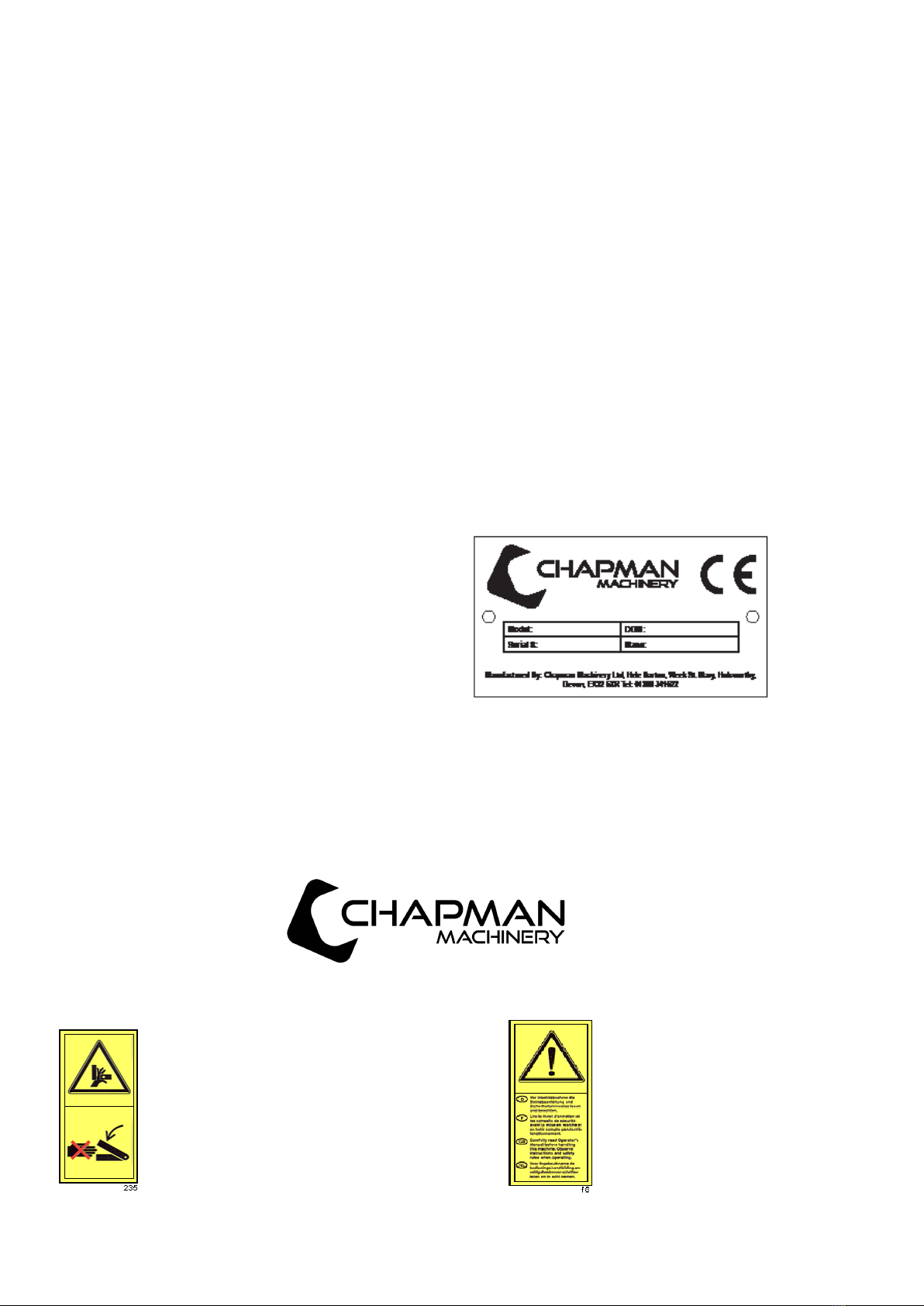
Identification
Each machine is fitted with a serial plate (shown below) which details the following:
1. Model
2. Date of Manufacture (DOM)
3. Serial Number
4. Mass
When enquiring regarding spares or additional
equipment, ensure you have this information to hand.
Implement Decals
If your implement does not contain all of the decals shown below, please contact Chapman Machinery for
replacement decals before use. Note: All decals must be present and visible. It is imperative that these are replaced
if damaged to prevent potential harm to users.
* Caution, crush hazard –never reach
into crush area as parts may move
trapping appendages
* Carefully read operators manual
before handling this machine. Observe
instructions and safety rules when
operating.
Page 6
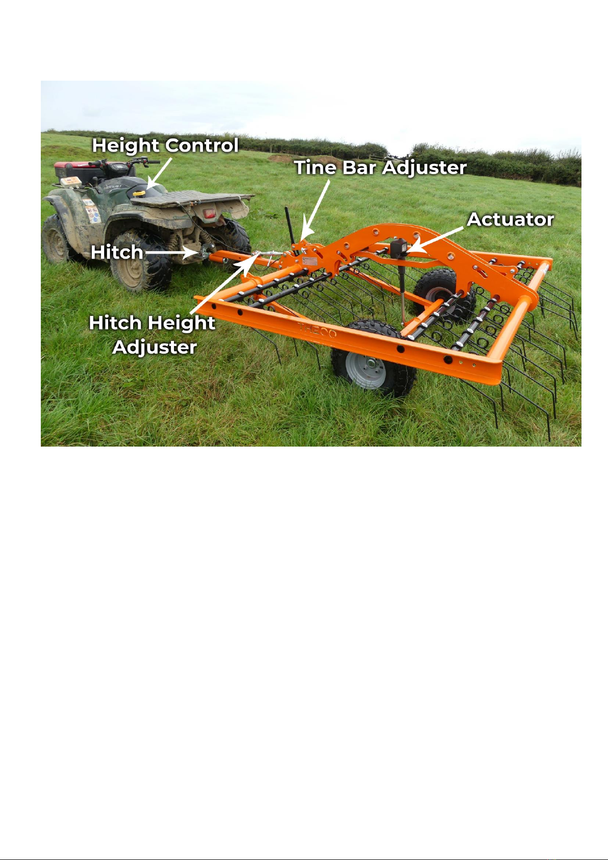
Component Identification

Page 7
Attachment
Before Attaching the Machine
Before attachment, ALWAYS ensure the following:
- All safety guards & decals are in good working order and correctly fitted
- Lubrication points have been lubricated as per scheduled maintenance period
- The tyres are free of damage and inflated to the correct pressure
- Electrical connections are free of dirt and moisture
Attaching the Machine
NOTE: This machine is designed to attach to the towing vehicle through a 50mm diameter ball hitch.
1. Reverse the towing vehicle up to the machine.
2. Attach the machine onto the towing vehicle’scoupling. Adjust drawbar angle is necessary to ensure main frame of
machine is parallel with ground when in working height, this ensures even tine contact across the 4 rows of tines.
3. Attach the control cable to the control socket fitted on the towing machine, ensuring a secure connection.
4. If required, adjust tine angle setting before lowering machine into work mode.
WARNING: ENSURE CONTROL EQUIPMENT IS SECURELY ATTACHED TO THE TOWING VEHICLE BEFORE USE,
REPLACEMENT CONTROL BOX ASSEMBLIES ARE EXPENSIVE!
Initial Set-up
Tine Angle
The tines on the TH200 can be set to three settings of aggressiveness, using the black tine bar adjuster
located just behind the machine drawbar. Pulling the adjuster forwards (towards the towing vehicle) will
make the tines less aggressive and pushing the adjuster rearwards will make the tines more aggressive. The
adjuster s fixed in place once set using a pin and retaining clip. *We recommend you begin operation with
the tines in the middle setting and adjust as required thereafter*
Height
The working height of the machine is set using the electronic actuator and control box. Pressing the
relevant up / down arrow will raise or lower the main frame accordingly. The TH200 should only be
transported across fields with the height at it’s maximum, and then lowered into use as required. The
TH200 should be lowered to allow weight onto the tines, such that consistent ground contact is achieved
by the tines. The wheels will always carry some weight, to ensure the unit tows easily and travels over
rough terrain smoothly.

Page 8
Initial Test Operation
In order to familiarise the operator(s) with the machine, first adjust the tines and machine height in the
yard, before going out to the pasture to commence work. This will ensure the operator is fully familiar with
the operation of the machine. During this period the angle of the drawbar should be adjusted to suit the
towing vehicle, such that the main frame of the TH200 runs level with the ground when the unit is in a
working height.
Once the operator(s) are familiar with the machine and operation, the tank can be drained and refilled with
water / herbicide as per the herbicide manufacturers recommendations.
Operation
Ensure that the operator is suitably qualified to use a machine of this nature and that they have fully read
and
understood this manual - they should be aware of all safety aspects relating to the safe use of the machine.
AFTER APPROXIMATELY ONE HOUR OF WORK WITH A NEW MACHINE, ALL NUTS, BOLTS AND DRIVE BELTS
SHOULD BE CHECKED FOR TIGHTNESS AND ADJUSTED AS NECESSARY!
Operation
1. Set desired tine angle with machine in transport position (ie. height at maximum). Recommended
start position is middle hole on tine adjustment.
2. Drive into paddock and using control box, lower tines onto ground until all tines are in contact with
the ground. Ensure main frame is roughly parallel with ground and adjust drawbar angle if necessary.
3. The TH200 is quite heavy and the weight of the machine can be used to increase the pressure on the
tines –more pressure = more tine penetration through the sward. Heavy harrowing in the spring will
usually need more tine pressure and lighter de-thatching in the summer will need less pressure.
4. Harrow the field by first running around the edge a few times to allow turning room, and then
traversing the field in straight lines. For some pastures a second pass at 90° to the first pass will be
required.
5. Once finished harrowing raise to transport position (maximum height) for transport.
Forward Speed
A forward speed of around 5mph will typically produce the best results, however this may need to be
increased or reduced depending on the ground conditions and depth of grass sward.
Operating Limits
WARNING: DO NOT OPERATE BEYOND OPERATING LIMITS, DAMAGE TO MACHINERY OR INJURY TO
OPERATOR MAY OCCUR.
Minimum / Maximum Temperature: 5°C / +40°C

Page 9
Storage
For extended periods of storage, it is advisable that the machine be kept in a clean dry environment
protected from the elements to avoid risk of corrosion.
Troubleshooting
Problem
Possible Causes
Remedies
Unit will not raise or lower
Shortage in wiring (may be
indicated by unit losing powerwhen
run button pressed)
Check plug and battery connection
are free from dirt and making good
contact
Actuator Fault
Replace motor, contact distributor
Switch Fault
Replace switch, contact distributor
Poor tine contact with ground
Working height too high
Lower unit
Tines worn
Inspect tines, replace if worn
Drawbar angle incorrect
Adjust drawbar adjuster so that
main frame is parallel with ground
when at working height

Page 10
Warranty
The Chapman Warranty
Chapman Machinery Ltd (herein ‘Chapman’ or ‘Chapman Machinery’) warrants that the machine referred to in the Warranty Registration Form will be free
from manufacturing defects for a period of 24 months from the date of sale. This warranty does not affect your statutory rights, but merely adds to them.
Should you have a problem within 24 months from the date of sale please contact your original dealer, or Chapman Machinery’s Service Department.
Any part found to be defective during this period will be replaced or repaired, at our discretion, by the dealer or a authorised Service Engineer.
Warranty Conditions
1. The Warranty Registration Form must be completed and returned to Chapman Machinery Ltd within 30 days of the date of sale
2. This warranty does not cover defects arising from fair wear and tear, wilful damage, negligence, misuse, abnormal working conditions, use in competition,
failure to follow Chapman Machinery’s instructions (oral or written, including all instructions and recommendation made in the Operator’s Manual) or
alteration or repair of the
machinery without prior approval.
3. The machinery must have been serviced in accordance with the Operator’s Manual and the Service Log must have been
kept up to date and made available tothe
dealer should service, repair or warranty work be undertaken.
4. This warranty does not cover claims in respect of wearing parts such as blades, flails, paintwork, tyres, belts, hydraulic hoses, bearings, bushes, linkage pins,
top links, ball ends unless there is a manufacturing or material defect or the cost of normal servicing items such as oils and lubricants.
5. This warranty does not cover any expenses or losses incurred whilst the machinery is out of use for warranty repairs or parts replacement.
6. This warranty does not extend to parts, materials or equipment not manufactured by Chapman Machinery, for which the Buyer shall only be entitled to the
benefit of any such warranty or guarantee given by themanufacturer to Chapman Machinery. Only genuine replacement parts will be allowable for warranty
claims.
7. All parts replaced by Chapman Machinery under warranty become the property of Chapman Machinery and must be returned to Chapman Machinery if
so requested. Such parts may only be disposed of after a warranty claim has been accepted and processed by Chapman Machinery.
8. Chapman Machinery is not liable under this warranty for any repairs carried out without Chapman Machinery’s written consent or without Chapman
Machinery being afforded a reasonable opportunity toinspect the machinery the subject of the warranty claim. Chapman Machinery’s written consent must,
therefore, be obtained before any repairs are carried out or parts replaced. Use of non- Chapman Machinery parts automatically invalidates the Chapman
Warranty. Failed components must not be dismantled except as specifically authorised by Chapman Machinery and dismantling of any components without
authorisation from Chapman Machinery will invalidate this warranty.
9. All warranty claims must be submitted to Chapman Machinery on Chapman Machinery Warranty Claim Forms within 30 days of completion of warranty
work.
Using the machine implies the knowledge and acceptance of these instructions and the limitations contained in this
Manual.
Transfer of Warranty
The Chapman warranty be transferred to a subsequent owner of the machinery (for use within the UK only) for the balance of the warranty period subject to
all of the stated warranty conditions and provided that the Change of Owner form is completed and sent to Chapman Machinery within 14 days of change of
owner- ship.
Chapman Machinery Ltd retain the right to refuse transfer of warranty.
Chapman Machinery reserves the right to make alterations and improvements to any machinery
without notification and without obligation to do so.

Page 11
EC DECLARATION OF CONFORMITY
Machinery Directive 2006/42/EC
Chapman Machinery Ltd
Hele Barton
Week St. Mary
Holsworthy
Devon
EX22 6XR
The Products Covered by this Declaration
Product: TH200 Tine Harrow
Standards and Regulations used: Machinery Directive 2006/42/EC
Place of Issue: United Kingdom
Name of Representative: James Chapman
Position of representative: Director
The Basis on which Conformity is being Declared
I declare that as the authorised representative, the above information in relation to the supply /
manufacture of this product, is in conformity with the stated standards and other related documents
following the provisions of Machinery Directive 2006/42/EC directives
The products described above comply with the essential requirements of the directives specified.
Signed:
Date: ......21/01/2014..................
Table of contents


