Mantis DELUXE 7264 User manual

7264 DELUXE 4-CYCLE TILLER/CULTIVATOR
OWNER’S MANUAL
IMPORTANT!
ASSEMBLY INSTRUCTIONS START ON PAGE 6!
PLEASE REVIEW THE WARNING & SAFETY INFORMATION ON PAGES 3-5
AND THE ASSEMBLY INSTRUCTIONS BEFORE UNPACKING THE BOX.
401777 Deluxe 4C iller-Cultivator_400752. iller/Cultivator 8/12/11 10:51 AM Page 1

Here’s your new MANTIS Tiller . . .
the lightweight wonder that’s Changing
the Way Americans Garden.®
Unlike big tillers, your MANTIS Tiller
weighs only 26 pounds. So it lifts
easily, handles smoothly, tills and
weeds precisely. And, unlike other
small tillers, it features serpentine tines
that churn soil to ten inches deep. It
creates a soft, smooth seed bed, even
in problem soil.
Once you know how to use your tiller
correctly, we guarantee you’ll love it.
So first, please read this manual. It
shows, step by step, how to use your
tiller safely.
If you have questions about any topic
in this Manual, or for the name of
your local dealer, call 1-800-366-6268
toll free, Monday - Saturday, 8:00am
to 5:00pm, Eastern Time.
2
Table of Contents
Safety Rules & Warnings
. . . . . . . . . . . . . . . . . .
3-5
Assembly and Oil Level . . . . . . . . . . . . . . . . .6-14
Starting . . . . . . . . . . . . . . . . . . . . . . . . . . . . . . . .15
Additional Information . . . . . . . . . . . . . . . . . . . .16
Getting to Your Garden . . . . . . . . . . . . . . . . . . . .16
Tilling & Cultivating . . . . . . . . . . . . . . . . . . .17-19
Tine Positioning . . . . . . . . . . . . . . . . . . . . . . . . .19
Maintenance . . . . . . . . . . . . . . . . . . . . . . . . . . . .20
Storage . . . . . . . . . . . . . . . . . . . . . . . . . . . . . . . .21
MANTIS Tiller Assembly Layout . . . . . . . . .22-23
Limited Warranty Information . . . . . . .Back Cover
Welcome to the World of
Mantis Gardening
Attention Mantis Product
Owners! Get maintenance tips
for your Mantis product on our
website at www.mantis.com
401777 Deluxe 4C iller-Cultivator_400752. iller/Cultivator 8/12/11 10:51 AM Page 2

3
Safety R les & Warnings
You will notice Safety Rules and Important Notes throughout this Owners Manual. Make sure you understand
and obey these warnings for your own protection.
I. Special Safety Information
WARNING • DANGER
ATTENTION: THIS SYMBOL POINTS OUT
OUR IMPORTANT SAFETY INSTRUCTIONS.
WHEN YOU SEE THIS SYMBOL,
HEED IT’S WARNING!! STAY ALERT!!
WARNING • DANGER
TO REDUCE THE POTENTIAL FOR ACCIDENTS, COMPLY
WITH THE SAFETY INSTRUCTIONS IN THIS MANUAL.
FAILURE TO COMPLY MAY RESULT IN SERIOUS PERSONAL
INJURY, AND/OR EQUIPMENT AND PROPERTY DAMAGE.
WARNING • DANGER
IMPROPER USE OR CARE OF THIS TILLER
OR FAILURE TO WEAR PROPER PROTECTION
CAN RESULT IN SERIOUS INJURY.
READ AND UNDERSTAND THE RULES FOR SAFE OPERATION
AND ALL INSTRUCTIONS IN THIS MANUAL.
WEAR HEARING AND EYE PROTECTION.
II. Safety & Warnings
!
WARNING: he Engine Exhaust from this product contains chemicals known
to the State of California to cause cancer, birth defects or other reproductive harm.
!
! !
!
!
!
!
401777 Deluxe 4C iller-Cultivator_400752. iller/Cultivator 8/12/11 10:52 AM Page 3

DON’T FUEL, REFUEL, OR
CHECK FUEL WHILE
SMOKING, OR NEAR AN
OPEN FLAME OR OTHER
IGNITION SOURCE.
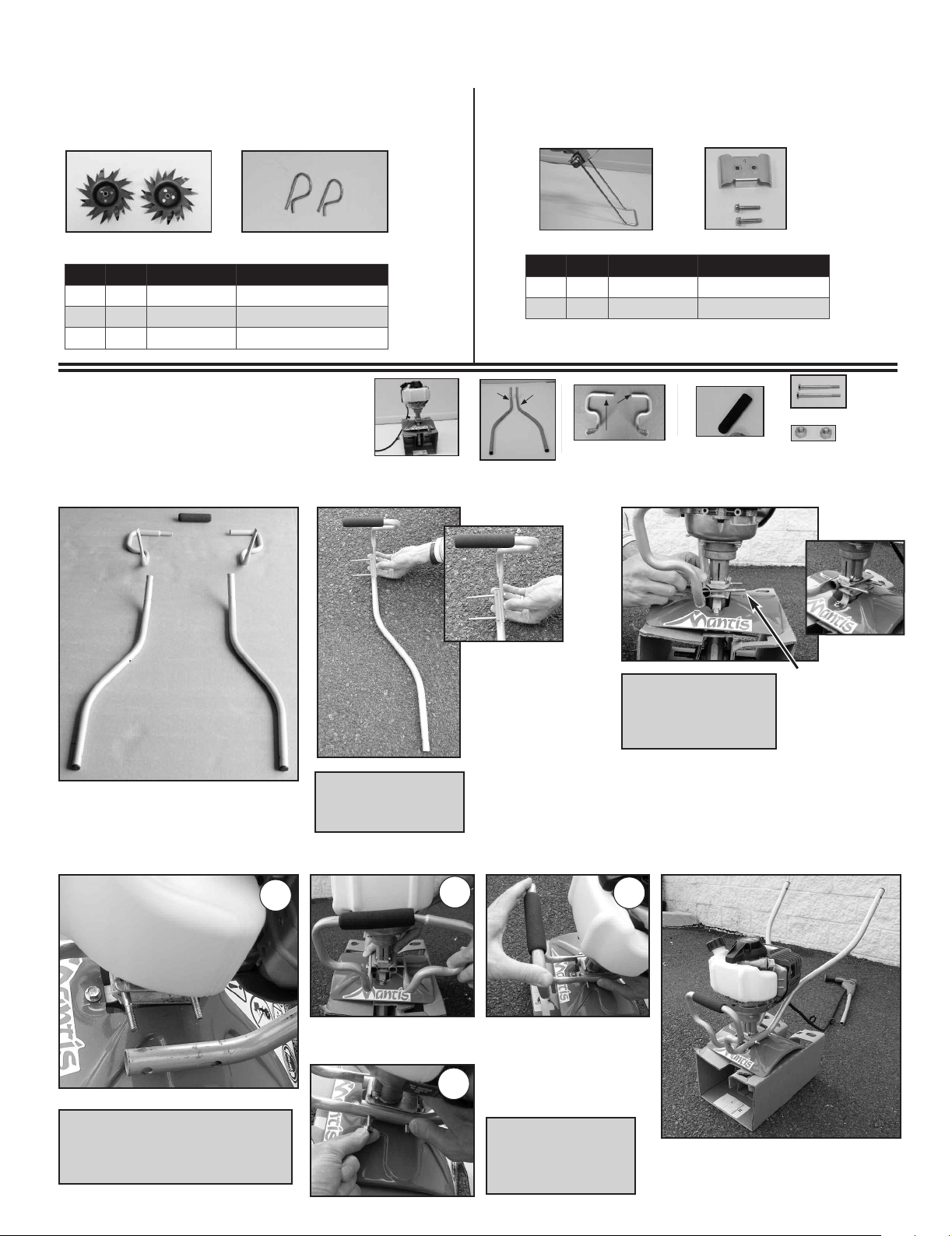
INCORRECT ASSEMBLY.CAUTION: WHEN
ASSEMBLING THE HANDLES,
MAKE SURE FUEL TANK FACES
AWAY FROM OPERATOR. THIS
IS THE REAR OF THE TILLER,
REFER TO ASSEMBLY
INSTRUCTION ON PAGE 7.
CUTTING HAZARD; KEEP
FEET AND HANDS AWAY
FROM ROTATING TINES.
WEAR EAR AND EYE
PROTECTION.
READ OWNER’S MANUAL
BEFORE USING TILLER, OR
PERFORMING ANY REPAIR
OR MAINTENANCE. KEEP
OWNERS MANUAL IN A
SAFE PLACE.
DO NOT CARRY THE TILLER
IN THIS POSITION.
WARNING • DANGER
IF THE TILLER IS USED IMPROPERLY OR SAFETY PRECAUTIONS ARE NOT FOLLOWED,
THE USERS RISK SERIOUS INJURY TO THEMSELVES AND OTHERS.
READ AND UNDERSTAND THIS MANUAL BEFORE ATTEMPTING TO OPERATE THIS TILLER.
! !
An important part of the safety system incorporated in this tiller are the
warning and information decals found on various parts of the tiller. hese
decals must be replaced in time due to abrasion, etc. It is your responsibility to
replace these decals when they become hard to read. he location and part
numbers (P/N) of these decals are illustrated below.
III. Safety Decal Information
4
IV. Warnings - Do’s
Read and understand the owner’s
manual. Pay particular attention to all
sections regarding safety.
1. Always keep a firm grip on both
handles while the tines are moving and/or
the engine is running. BE AWARE!! The
tines may coast after throttle trigger is
released. Make sure tines have come to a
complete stop and engine is off before
letting go of the tiller.
2. Always maintain a firm footing and
good balance. Do not overreach while
operating the tiller. Before you start to use
the tiller, check the work area for obstacles
that might cause you to lose your footing,
balance or control of the machine.
3. Thoroughly inspect the area where
equipment is to be used and remove all
objects, which can be thrown by the
machine.
4. Always keep area clear of children,
pets, and bystanders.
5. Always stay alert. Watch what you
are doing and use common sense. Do not
operate unit when fatigued.
6. Always dress properly. Do not wear
loose clothing or jewelry, they might get
caught in moving parts. Use sturdy gloves.
Gloves reduce the transmission of
vibration to your hands. Prolonged
exposure to vibration can cause numbness
and other ailments.
7. While working, always wear
substantial footwear and long trousers. Do
not operate the equipment when barefoot
or wearing open sandals.
8. Always wear ear and eye protection.
Eye protection must meet ANSI Z 87.1.
To avoid hearing damage, we recommend
hearing protection be worn whenever
using the equipment.
9. To reduce fire hazard, keep the
engine, and petrol/gas storage area free of
vegetative material and excessive grease.
10. Start the engine carefully,
according to the manufacturer’s
instructions and with feet well away from
tool(s).
11. Keep all nuts, bolts and screws
tight to be sure the equipment is in safe
working condition.
12. Use extreme caution when
reversing or pulling the machine towards
you.
13. Work only in daylight or good
artificial light.
14. Always be sure of your footing on
slopes.
15. Exercise extreme caution when
changing direction on slopes.
16. Always keep a safe distance
between two or more people when
working together.
17. Always inspect your unit before
each use and ensure that all handles,
guards and fasteners are secure, operating,
and in place.
18. Always maintain and examine your
Tiller with care. ollow maintenance
instructions given in manual.
19. Always store tiller in a sheltered
area (a dry place), not accessible to
children. The tiller as well as fuel should
not be stored in a house.
DON’T OPERATE
INDOORS
P/N 400630
P/N 430057
WARNING • DANGER
OPERATION OF THIS EQUIPMENT MAY CREATE
SPARKS THAT CAN START FIRES AROUND DRY
VEGETATION. A SPARK ARRESTOR IS INSTALLED.
THE OPERATOR SHOULD CONTACT LOCAL FIRE
AGENCIES FOR LA S OR REGULATIONS RELATING
TO FIRE PREVENTION REQUIREMENTS.
401777 Deluxe 4C iller-Cultivator_400752. iller/Cultivator 8/12/11 10:52 AM Page 4

V. Warnings - Don'ts
Don’t use tiller with one hand.
Keep both hands on handles with
fingers and thumbs encircling the
handles, while tines are moving,
and engine is running.
Don’t overreach. Keep a good
footing at all times.
Don’t run with the machine,
walk.
Don’t work on excessively
steep slopes.
Don’t attempt to clear tines
while they are moving. Never try
to remove jammed material before
switching the engine off and
making sure the tines have
stopped completely.
Don’t allow children or
incapable people to operate this
tiller.
Don’t operate while under
the influence of alcohol or drugs.
Don’t attempt to repair this
tiller. Have repairs made by a
qualified dealer or repairman.
See that only original Mantis parts
are used.
5
WARNING • DANGER
HANDLE FUEL WITH CARE, IT IS HIGHLY FLAMMABLE. FUELING A HOT ENGINE OR NEAR AN IGNITION
SOURCE CAN CAUSE A FIRE AND RESULT IN SERIOUS PERSONAL INJURY AND/OR PROPERTY DAMAGE.
! !
Always use fresh gasoline. Stale
gasoline can cause damage.
Always store fuel in containers
specifically designed for this
purpose.
Always pull starter cord slowly
until resistance is felt. Then pull cord
rapidly to avoid kickback and prevent
arm or hand injury.
Always operate engine with spark
arrestor installed and operating
properly. The use of spark arrestor
mufflers is required by law in the
state of California (Section 4442 of
the California Public Resources
Code), as well as in other states or
municipalities. ederal laws apply on
federal lands.
Stop the engine whenever you
leave the machine.
Allow the engine to cool before
storing in any enclosure.
If the fuel tank needs to be
drained, this should be done
outdoors.
Don’t
fuel, refuel or check fuel
while smoking, or near an open
flame or other ignition source. Stop
engine and be sure it is cool before
refueling.
Don’t
leave the engine running
while the tiller is unattended. Stop
engine before putting the tiller
down or while transporting from
one place to another.
Don’t
refuel, start or run this
tiller indoors or in an improperly
ventilated area.
Don’t
run engine when electrical
system causes spark outside the
cylinder. During periodical checks
of the spark plug, keep plug a safe
distance from cylinder to avoid
burning of evaporated fuel from
cylinder.
Don’t
check for spark with
spark plug or plug wire removed.
Use an approved tester.
Don’t
crank engine with spark
plug removed unless spark plug
wire is disconnected. Sparks can
ignite fumes.
Don’t
run engine when the odor
of gasoline is present or other
explosive conditions exist.
Don’t
operate the unit if
gasoline is spilled. Clean up spill
completely before starting engine.
Don’t
operate your tiller if there
is an accumulation of debris around
the muffler, and cooling fins.
Don’t
touch hot mufflers,
cylinders or cooling fins as
contact may cause serious burns.
Don’t change the engine
governor setting or over speed the
engine.
Don’t
attempt to remove spark
plug while engine is hot. Removing
a spark plug from a hot engine can
cause irreparable damage to the
engine and will void your warranty.
VI. Engine/ uel Warnings - Do’s
VII. Engine/ uel Warnings - Don’ts
401777 Deluxe 4C iller-Cultivator_400752. iller/Cultivator 8/12/11 10:52 AM Page 5

6
Removing Parts From Box
ASSEMBLY
Step 1
It is best to assemble the tiller
on a hard flat surface such as
a garage floor or driveway.
Step 2
Open top of shipping carton.
Your MANTIS®Tiller comes partially assembled.
The full assembly will take just a few minutes if
you follow the directions correctly.
Step 5
Remove component parts and lay on flat surface.
Step 3 Step 4
Remove tine box and oil. Remove cardboard insert.
Step 6 Step 7 Step 8
Lay box on wide flat side. Open bottom of the box and
lift box flaps up.
Return box to the standing position.
Do not remove upper
right throttle handle
assembly and engine
portion of the tiller in
this step.
Help ul Hint 1
Keep like items together.
Help ul Hint 2
CAUTION
When removing tine box,
handle the box with
extreme caution, Tines are
sharp and can come
through the cardboard box.
Ratchet
7/16” Wrench
3/8” Wrench
Extension
7/16”
Socket
TOOLS
NEEDED
WARNING • DANGER
IMPROPER ASSEMBLY OF THIS TILLER CAN RESULT IN SERIOUS INJURY. MAKE SURE TO FOLLO ALL INSTRUCTIONS CAREFULLY.
IF YOU HAVE ANY QUESTIONS, CONTACT OUR FACTORY AT 1-800-366-6268 OR AN AUTHORIZED MANTIS DEALER.
401777 Deluxe 4C iller-Cultivator_400752. iller/Cultivator 8/12/11 10:52 AM Page 6

7
ASSEMBLY (continued)
Step 9
Pull box straight up.
The right handle additional parts and tiller engine will be in the box cradle.
Do not remove the cardboard cradle from around the tiller base. The cradle will make
the assembly process easier for you.
Help ul Hint
Parts List
Lower Handle Assembly
Upper Handle Assembly
Key Qty. Part No. DescriptÚn
A 1 N/A TransmissÚn and Engine assembly
B 1 430023 Loop handle right half
C 1 430022 Loop handle left half
D 1 430025 Loop handle grip
E 1 430051 Lower handle, right
F 1 430050 Lower handle, left
G2 4049 3.25” Bolts
H 4 972 1/4-20 Two-way lock nut
I 1 430049 Carry Handle (with grip)
J 2 144-2 1/4-20 x 1-1/8 Hex head cap screws
E
J – 1/4-20 x
1-1/8 Hex head
cap screws
H – 1/4-20
Two-way
lock nut
B, C – Loop Handle
G – 3.25” Bolts
D – Loop handle grip
I – Carry Handle w/grip
E, F – Lower Handle
A – Transmission and
Engine Assembly
E – Right
B – Right
F– Left
C – Left
Key Qty. Part No. DescriptÚn
H 2 972 1/4-20 Two-way lock nut
J 2 144-2 1/4-20 x 1-1/8 Hex head cap screws
K 1 430004 Trigger handle assembly, right
L 1 430006 Handle assembly, left
M 1 430053 Middle handle, right
N 1 430052 Middle handle, left
O 1 430021 Handle brace
P 2 430038 Knob– 1/4-20 x 1.5 male
Q4 400523 Knob, two prongs, female
R 2 430039 Carriage bolt 1/4-20 x 2.25”
S 2 430048 Curved head bolt, 1/4-20x2”
T 2 395 Acorn nut
U 2 478 Throttle Clip
J – 1/4-20 x 1-1/8 Hex
head cap screws
H – 1/4-20
Two-way
lock nut
S – Curved
Head Bolts
T – Acorn
Nuts
U – Throttle Clips
R – Carriage
Bolts
Q – Knobs, Two-
Prong female
O – Handle Brace
M, N –Middle
handles
P – Knob 1/4-20
x 1.5 male
K, L – Handle Assembly
K-Right L-Left
M-Right
N-Left
401777 Deluxe 4C iller-Cultivator_400752. iller/Cultivator 8/12/11 10:52 AM Page 7

8
ASSEMBLY (continued)
Lower Handle Assembly
Parts Needed:
Tine Assembly Kickstand Assembly
Step 1
Layout parts.
Step 4
Slide lower left handle onto 3.25” bolts.
Lower Tiller Assembly should look
like above.
Finger tighten
nuts and bolts.
Slide left loop handle (C) into grip (D) and into
right loop handle (B).
Step 3
Place right
lower handle
assembly onto
unit as shown
above.
Step 2
• Insert grip (D)
onto the Right
Loop Handle (B)
• Line up holes on
Right Loop Handle
(B) and Lower
Right Handle (E)
• Place (2) 3.25”
bolts (G) through
holes.
One side only at a time.
Help ul Hint
Finger tight is one half
to one full turn.
Help ul Hint
Keep throttle cable out
of the way
.
Help ul Hint
Hold bolts on right side as you put
left side onto the bolts.
Help ul Hint
DD
BB
C
B
C
D
FE
E
B, C – Loop Handle
L
B – Right
C– Left
C
C
1
D – Loop handle grip
I – C
K
H – 1/4-20
Two-way
lock nut
L
C
T
C
1
L
T
x
K
G – 3.25” Bolts
E
x
L
E, F – Lower Handle
T
E
E– Right
F– Left
1
A
C
x
Z– Kickstand Brace Kit
Y – Kickstand
Key Qty. Part No. DescriptÚn
Y1 410158 Stand
Z 1 430037 Kickstand Brace Kit
X– Tine Retaining pinsV, W – Tines
Key Qty. Part No. DescriptÚn
V 1 438RA Tine assembly, right
W 1 438LA Tine assembly, left
X 2 418-1 Tine retaining pins
4A 4B 4C
4D
A– Transmission and
Engine Assembly
K
401777 Deluxe 4C iller-Cultivator_400752. iller/Cultivator 8/12/11 10:52 AM Page 8

9
Carry Handle Assembly
ASSEMBLY (continued)
Step 5
Place Carry Handle (I) on lower
handle bars and line up holes for bolts.
Place (2) 1-1/8” bolts (J) through holes and
finger tighten. 1/4-20 two-way lock nuts (H).
Hex head cap
screws go on
the inside and
nuts go on the
outside.
Help ul
Hint
Use tools and tighten all
fasteners of the lower
portion of the tiller.
(Steps 1 thru 5)
Kickstand Assembly
Step 6
Place kickstand brace on top
portion of lower handle with the
stamped arrow pointing up.
Fully assembled lower portion of the tiller.
Place kickstand below lower handle
so the holes of the kickstand line
up with the kickstand brace (Z).
Place (2) 1/4-20 serrated flange
screws (Za) through the holes in
the top brace and tread into
kickstand (Y).
Tighten kickstand (Y) and
kickstand brace (Z) with (2) 1/4-20
serrated flange screws (Za) using
3/8” wrench.
Ratchet
7/16” Wrench
Extension
7/16”
Socket
Parts Needed:
Parts Needed:
I – Carry Handle w/grip
J – 1/4-20 x
1-1/8 Hex head
cap screws
H – 1/4-20
Two-way
lock nut
E
T
x
Z – Kickstand Brace Kit
Y – Kickstand
5A
6A 6B 6C
6D
5B
IMPORTANT
401777 Deluxe 4C iller-Cultivator_400752. iller/Cultivator 8/12/11 10:52 AM Page 9

10
Tine Assembly
Upper Handle & Tube Assembly
ASSEMBLY (continued)
Step 7
For information on tine
positioning – Cultivating vs.
Tilling – please see page 16
Help ul Hint
The nuts go on the inside
of the tube hidden under
the Mantis logo brace.
Help ul Hint 1
The flat portion of the
middle tube (M) should
face away from the
Mantis logo on the
handle brace (O).
Help ul Hint 2
Repeat
Step 9 or
the le t
side
be ore
attaching
to the
lower
handle
assembly
Remove cardboard cradle
from tiller.
Take middle tube (M) and attach to handle brace (O) using
1/4-20 x 1-1/8 hex head cap screws (J). Finger Tighten 1/4-20
two-way lock nuts (H).
Step 8
Step 9
Layout parts.
Place tines (V, W) on tine
shaft with “D” shaped hole
facing outward.
Secure with tine retaining
pins (X).
Put Kickstand down and rest
tiller on kickstand and tines.
M
M
N
O
K
L
Parts Needed:
Parts Needed:
J– 1/4-20 x 1-1/8 Hex
head cap screws
H – 1/4-20
Two-way
lock nut
M, N –Middle
handles
K, L – Handle Assembly
K-Right L-Left
M-Right
N-Left
O – Handle Brace
K
X– Tine Retaining pins
K
V, W – Tines
7A
9A 9B
9C 9D
7B 7C 7D
401777 Deluxe 4C iller-Cultivator_400752. iller/Cultivator 8/12/11 10:53 AM Page 10

11
ASSEMBLY (continued)
Step 10
Take right handle (K) and slide it between middle handle tube (M) and brace (O).
Step 11
Attach the upper handle assembly
to the lower handle assembly.
Place carriage bolts (R)
through the upper handle
assembly and through the
lower handle assembly.
Thread the two-prong
knobs (Q) onto the
carriage bolts (R). Do not
tighten at this time.
Thread two-prong knob (Q) onto
exposed bolt (S) two full turns.
• Place curved-head (S) bolt into slot
• Curved-head bolt (S) should come
out of middle tube.
Slide curved head bolt (S) into bottom
slit of the upper handle.
Repeat Step 10 or the le t side handle.
Rest the handles on the ground
to help in the assembly process.
Help ul Hint
K
S
S
Q
K
MO
O
S – Curved
Head Bolts
Q– Knobs, Two-
Prong female
O
Parts Needed:
R – Carriage
Bolts
Q – Knobs, Two-
Prong female
O
Parts Needed:
10A
11A 11B 11C
10B
10C
10D
10E
401777 Deluxe 4C iller-Cultivator_400752. iller/Cultivator 8/12/11 10:53 AM Page 11

12
ASSEMBLY (continued)
Step 12
Raise upper handle to full extension.Fully tighten the (2) two-prong knobs
(Q) shown above.
• Install acorn nuts (T) using the
7/16” wrench.
• Do not over tighten.
Step 13
Select hole position Start
in lowest hole position and
adjust up as needed.
To make adjustment easier
make sure two-prong knobs
installed in Step 10 are not
too tight. Loosen if necessary.
* Height settings are suggestions only. Select the position
that is most comfortable to you.
5’10” and
under use
position #1
5’11” to
6’2”use
Position #2.
6’3” and
over use
Position #3.
Step 14
Install the throttle clips.
Tighten round knob (P)
into the handle brace on
the right and left handles
to secure handle length.
Height Adjustment Feature
If you need additional information or
have questions contact Mantis at
1-800-366-6268 or Mantis.com
Help ul Hint
Q
T–
Acorn
Nuts
Parts Needed:
P– Knob 1/4-20
x 1.5 male
Parts Needed:
Suggested
Height Settings*
12A
13A
13B
12B
Fully tighten the (2)
two-prong knobs (Q)
shown above.
Fully tighten
nuts and bolts
installed in
Step 9 located
underneath
handle brace.
13C
12C
IMPORTANT NOTE:
Be sure you have proper throttle
movements and that the throttle cable is
not wrapped or twisted around the
handle bar. Hold down the lockout lever
fully squeeze the throttle trigger and let go.
The throttle triangle must click in both
directions. If there is any doubt remove air
filter and visually check that the throttle
triangle hits both the idle screw and the full
open stop. THIS MUST BE DONE BEFORE
STARTING THE ENGINE.
IMPORTANT NOTE:
Make sure you have
installed the handles
properly. When you stand
behind your tiller, holding
the handles, the gasoline
tank should face away
from you.
WARNING:
Improper throttle installation can
cause tines to rotate unexpectedly.
IMPORTANT NOTE:
Before you use your MANTIS
Tiller, read the Safety Rules
& Warnings on pages 3-5.
Q
13D
401777 Deluxe 4C iller-Cultivator_400752. iller/Cultivator 8/12/11 10:53 AM Page 12

13
Assembly (contin ed)
Assembling the Tines
for Tilling
1. Slide the tines onto the axle
shafts. The “D”-shaped hole goes
on the outside. (Picture 1)
2. Make sure you’ve installed the
tines properly for tilling. Liken
the tines to your fingers. When
your palm faces the ground, your
fingers curl down. Stand behind
the Tiller and hold your hand next
to the tines. Do the tine blades
curl down, as your fingers do? If
so, they are in the tilling position.
(To switch to the cultivating
position, see page 14.)
3. To secure each tine to the axle,
insert a tine retaining pin.
IMPORTANT NOTE:
Before starting your
4 Stroke/Mantis Tiller, add the
premeasured (80ml) bottle of
4 stroke engine oil. See 4 Stroke
Tiller Engine Manual and
information below for details.
IMPORTANT NOTE:
Before you use your
MANTIS Tiller, read the
Safety Rules & Warnings
on pages 3-5.
Checking the Oil evel in
the Engine’s Oil Sump
IMPORTANT NOTE: Before using
your new Mantis 4-Stroke Tiller for
the first time, it is important to check
the oil level in the engines oil sump.
The bottle of oil supplied with this
machine holds 80ml of the correct
grade of engine oil. The sump of the
engine holds 80ml of oil.
Please follow the notes below for
f ll instr ctions how to check the
oil level in the engine.
How to fill the engines oil sump
before using your new Mantis
Tiller:
1. Rock the tiller forward so that it
rests on its front loop handle.
2. Remove the grey sump plug and
top up the oil using the correct
type of oil so that it is level with
the inner first thread of the sump
plug. (Picture 2)
Oil type 10W/40 or 20W/40 can
be used if the specified grade is
unavailable.
Picture 1
Picture 2
WARNING • DANGER
FUEL IS EXTREMELY FLAMMABLE. HANDLE IT WITH
CARE. KEEP AWAY FROM IGNITION SOURCES. DO NOT
SMOKE WHILE FUELING YOUR EQUIPMENT.
!!
Never use starting fluids as they
will cause permanent engine
damage. Using them will void the
warranty. Before you use the
tiller, read the Safety & Warning
rules on pages 3-5.
IMPORTANT NOTE:
Check the oil level in the engine before each use. If oil is low,
top it off with 10W-30 before using. See your 4 Stroke Tiller
Engine Manual and information above for details.
401777 Deluxe 4C iller-Cultivator_400752. iller/Cultivator 8/12/11 10:53 AM Page 13

14
High pull force Handle locked in place
Engine must be resting on a flat surface on the fuel tank
This position does not allow
for a proper oil level reading
and may cause overfilling.
Oil Overfill Warning
Do not overfill! Adding too much or
too little oil may cause damage to the
engine and void the warranty.
Overfilling may cause:
1. Hard starting or a locked piston -
caused by excess oil in the
combustion chamber.
2. Poor engine performance and loss
of power
3. Excessive smoke coming from the
muffler and around the engine
while running.
4. Oil leaking form the
carburetor/aircleaner.
5. Oil leaking from the muffler.
Corrective Action
If you suspect the engine is
overfilled the following
procedure should remove the
excess oil from the crankcase and
valve cover.
If the engine is overfilled, oil will
enter the crankcase and it does
not simply pour out of the oil fill
opening. The excessive oil has to
be pumped out as the engine
runs. Checking the oil level and
draining any excess between
multiple 30 second running
intervals will bring the oil back to
the proper level.
1. Place the engine on a level
surface resting flat on the front
loop handle and remove the oil
fill cap/dipstick. Use a catch
basin for any oil that overflows
from the oil fill opening.
2. Replace the oil fill
cap/dipstick and run the
engine for approximately 30
seconds then repeat step one.
Continue steps 1 & 2 until oil
no longer overflows when the
oil fill cap/dipstick is
removed.
3. Once the oil level is corrected
the engine may continue to
smoke while running for
several minutes while the
residual oil burns off.
Assembly (contin ed)
Proper Oil Fill/ evel
Check Position
401777 Deluxe 4C iller-Cultivator_400752. iller/Cultivator 8/12/11 10:53 AM Page 14

15
WARNING
AVOID ACCIDENTAL BLADE
ENGAGEMENT
DO NOT SQUEEZE THE THROTTLE
TRIGGER WHEN STARTING.
MAINTAIN PROPER IDLE SPEED
ADJUSTMENT (2500-3 00 RPM)
TO START YOUR
TI ER FOR THE
FIRST TIME:
irst, fill the fuel tank with the
proper amount of gasoline (Use
branded 89 octane (R+M+2)
unleaded gasoline or gasohol—
maximum 10% ethyl alcohol, or
15% MTBE, no methyl alcohol.)
Mantis Tiller Starting
Instructions
(4 Stroke 25cc engine)
Cold Engine
1. Place the o/Iswitch into the I
“start/on” position. (Picture 1)
2. Choke the engine (or close
the choke. Move choke up to the
closed position.) (Picture 2)
3. Push primer bulb 6 times.
(Picture 3)
4. Pull grip slowly until you feel
resistance then pull briskly.
(Picture 4)
5. Once the engine is running,
slowly push the choke lever
down to the run position—the
engine will continue to run.
(Picture 5)
Warm Engine
1. Push ignition switch to I
“start/on” position.
2. Pull grip slowly until you feel
resistance then pull briskly.
Make sure the choke is in the
open, or run, position.
NOTE: When the choke is
closed, never pull the cord more
than four or five times. Over-
pulling may cause flooding.
ollow these steps whenever you
are starting the engine “cold”, or
when the engine has run dry and
you have just added fuel.
Remember, always use short,
brisk pulls. Don’t give the cord
a long, forceful yank. And, do
not let the cord snap back into
the starter housing.
Picture 4 Picture 5 Picture 6
Picture 1
Picture 2 Picture 3
Starting !!
How to Stop the Engine
Simply push the o/I“stop/ start”
switch to “o” (Picture 6). This will
stop the engine instantly. If it
should ever fail to do so, just pull
the choke up to the closed position.
The engine will stop at once.
About the Choke
The choke controls the amount of
air drawn into the engine. Your tiller
will run only if the choke is open.
IMPORTANT!
It is normal for your
4 stroke engine to smoke for
the first minute or two of
operation, however it is not
necessary for this to occur
every time. This is a result of
the oil being pulled through
the engine for lubrication.
WARNING • DANGER
IF ENGINE DOES NOT STOP WHEN SWITCH IS PUT IN THE STOP
POSITION, RELEASE THE THROTTLE, ALLOW ENGINE TO IDLE, PUT THE
TILLER DOWN AND PULL THE CHOKE BUTTON OUT TO SHUT ENGINE
DOWN. HAVE PRODUCT SERVICED BEFORE USING.
!!
401777 Deluxe 4C iller-Cultivator_400752. iller/Cultivator 8/12/11 10:53 AM Page 15

16
WARNING • DANGER
I
F ENGINE DOES NOT STOP WHEN SWITCH IS PUT IN THE STOP POSITION, RELEASE THE
THROTTLE, ALLOW ENGINE TO IDLE. PUT THE TILLER DOWN, AND SLIDE
THE CHOKE LEVER FORWARD TO THE COLD START (CLOSED) POSITION.
CHECK AND RETURN IGNITION SWITCH TO ON POSITION BEFORE STARTING ENGINE AGAIN.
Additional Information
Walk it.
Once your tiller is running, you
can “walk” it to your garden. Just
hold down the throttle lock
outlever and squeeze the throttle
trigger gently and let the tiller “tip-
toe” across your yard on its tines.
It won’t hurt your lawn. (Picture 1)
Carry It.
Make sure the engine is off.
Then use one hand to grasp the
front loop handle. Use the other
hand to hold the carry handle.
(Picture 2) Then lift your tiller and
carry it to your garden. Since it
weighs only 26 pounds, it won’t
strain your muscles or tire you out!
Take It for a Ride.
You can easily transport your
MANTIS Tiller to a friend’s or
relative’s house. Just empty the
fuel tank. (This is crucial.) Then
stow your Tiller in the trunk of
your car or truck. It fits easily.
And you can put it in and take it
out without straining your back.
How to get your tiller to your garden
Picture 1
Picture 2
Picture 3
!!
A Tip for Extending Your
Engine’s ife
After you start the engine, let
your tiller warm up for two to three
minutes before you use it. Then,
before you put your tiller away, let it
idle for a minute to give the engine
a chance to cool down.
Operation
With engine running, and both
hands on the handles, hold down the
throttle lock out lever (Picture 4),
then squeeze the throttle trigger
gradually to increase the engine
speed and engage the tines.
NOTE: This step must be
repeated each time your tiller
trigger is released.
A Special Feature (with the
idle set properly and the
engine running)
Even when the engine is running,
the tines won’t turn unless you
squeeze the throttle lever on the
handlebars. And, when you release
the throttle lever, the tines will stop.
WARNING
NEVER CARRY YOUR TILLER AS
THE PERSON IN PICTURE 3 IS
DOING. IF YOU DO, YOU WILL
SUFFER SERIOUS INJURY.
!!
Throttle Trigger
Throttle
Lock-out Lever
Picture 4
401777 Deluxe 4C iller-Cultivator_400752. iller/Cultivator 8/12/11 10:53 AM Page 16

Tilling
WARNING • DANGER
IF YOUR TINES GET JAMMED OR ENTANGLED, SHUT OFF THE ENGINE AT ONCE.
REMOVE THE OBSTRUCTION WHILE THE ENGINE IS OFF.
NEVER TRY TO REMOVE AN OBSTRUCTION WHILE THE ENGINE IS RUNNING.
SERIOUS INJURY CAN RESULT.
! !
17
Tilling
Now You’re Ready to Use
Your MANTIS Tiller.
If you’ve seen other tillers, your
MANTIS Tiller may surprise you. It tills
best when you pull it backward! You see,
when you pull your MANTIS Tiller
backward, you give extra resistance to the
tines, so they dig deeper. (Picture 1)
What’s more when you go backward, you
erase your footprints. So your soil stays
light and fluffy. With other tillers, by
contrast, you walk right over the soil
you’ve just tilled, packing it down, so it’s
less plantable.
Run Your MANTIS Tiller like
a Vacuum Cleaner.
Place your Tiller at the head of the row
or area you want to till. Start it up. Then
use an easy rocking motion. irst, pull
your Tiller backward. Then use an easy
rocking motion. Again, pull your Tiller
backward. Then, let it move forward just a
little bit. Then pull it backward again.
This will help you till deeper.
Keep repeating these steps until you’ve
tilled an entire row. Start again on the
next row. It’s much like running a
vacuum cleaner! (Picture 2)
You Can Even
Control Depth.
For Deeper Tilling:
Move your Tiller slowly back and forth,
as you would a vacuum cleaner. Work the
same area over and over until you’ve dug
to your desired depth. (Picture 3)
For Shallow Tilling:
Switch the tines to the cultivating
position. (See page 10 to learn how.) Then
move your Tiller quickly over your soil
surface.
For Big Weeds or Tough Roots:
Let your Tiller rock back and forth over
the tough spot, until the tines slice
through the weed or root.
Your MANTIS Tiller Handles
Special Tilling Projects.
Want to turn part of your lawn into a
colorful flower border? Your MANTIS
Tiller makes it easy! Just run your Tiller
back and forth until the sod begins to
break up. Then continue tilling. Your
Tiller will chop the clumps of sod until
they’re fine. Then, it will work them into
the soil. Pretty soon, you’ll have a soft,
fresh planting bed.
WARNING • DANGER
THE OPERATOR OF THIS TILLER IS RESPONSIBLE FOR
ACCIDENTS OR HAZARDS OCCURRING TO HIMSELF, OTHER PEOPLE
OR THEIR PROPERTY.
Picture 1
Picture 2
Picture 3
! !
401777 Deluxe 4C iller-Cultivator_400752. iller/Cultivator 8/12/11 10:53 AM Page 17

How about a family-
size vegetable garden?
Nowadays many gardeners
prefer small gardens —
especially in the suburbs, where
space is at a premium. But, if
you’re fortunate enough to own a
large lot, you can create a bigger
garden — a half acre or more.
Although your Mantis Tiller
could handle the job, the project
could be completed faster if you
were to hire someone with a
tractor or larger tiller to break the
ground for you. This is a one-
time-only investment that’s well
worth the small cost.
Your MANTIS Tiller
Makes Weeding a
Pleasure!
As a tiller, your MANTIS
Tiller works the soil down to 10”
(25.4 cm) deep. But, as a
cultivator, it gently cultivates the
surface, only 2" to 3" (5.09 cm to
7.62 cm) deep.
irst, you must switch the tines
to the weeding position. This
takes less than a minute.
Then, your MANTIS Tiller’s
sharp “tine teeth” will slice up
those pesky weeds, burying them
as you go along. And, since the
tines in this position won’t dig
too deep, they won’t hurt your
plants’ precious root systems.
The result? Your Tiller will cut
your weeding time in half, and
turn a tiresome chore into a
pleasure.
How to Switch From
Tilling to Cultivating
Position
1. Make sure your Tiller is off.
2. Remove the retaining pins
from the tines. (Picture 2)
3. Remove the tines from the
axle.
4. Place the right-side tine onto
the left-side axle. Place the left
side tine onto the right-side axle.
The “D” hole should be to the
outside.
5. Here is how to make sure
you’ve installed the tines
properly. Stand behind the Tiller
and hold your hand, palm up,
next to the tines. Do the tine
points curl up, as your fingers
do? If so, they are in the correct
cultivating position. (See photos
on Page 19)
6. Reinsert the pins.
Picture 1 Picture 2
18
Tilling
IMPORTANT
To change the tines on your
4 Stroke Mantis Tiller, push the
tiller forward and allow it to
rest on the loop handle.
! !
401777 Deluxe 4C iller-Cultivator_400752. iller/Cultivator 8/12/11 10:53 AM Page 18

19
Now You’re Ready to
Cultivate or Weed.
Guide your Tiller where you
want to weed and start it up. Pull
your Tiller backward slowly, then
let it move forward a bit, in a
gentle rocking motion. Watch it
slice, shred, and bury those
weeds!
Got tough weeds? Lighten your
pressure on the throttle to slow
your Tiller down. Then work back
and forth until your Tiller chops
up the weeds. It’s easy and
effective!
Remember, any tiller will
tangle in tall grass, stringy vines,
or super-big weeds. So, if you
have a “backyard jungle,” first
use a knife, pruner, or brush
cutter to chop up the overgrowth.
If the tines become tangled
anyway, turn the engine off
completely before trying to
clear them.
The optional Tine Detangler
(Item #1322) will clear tines in a
jiffy. Contact your local authorized
Mantis dealer or call 1-800-366-
6268 to order.
C ltivating
Tilling Position
Tine teeth point in the same
direction as the rotation of the
tine; or toward the front of the
Tiller, away from the operator.
Cultivating Position
Tine teeth point in the
opposite direction as the rotation
of the tine. Tines point toward the
back of the tiller, or toward the
operator.
Your Mantis Tiller
Will Weed Between Narrow Rows!
Your Mantis Tiller is a
precision weeder that easily fits in
tight places. So don’t be afraid to
weed anywhere: between plants
and shrubs, in corners, against
fences, on raised beds, in wide
rows, even in very narrow rows.
Your Mantis Tiller weeds six to
nine inches wide. So you can run
it in a tightly planted garden
without damaging your delicate
plants. That’s good news for
suburban gardeners, who often
have to plant rows close together!
401777 Deluxe 4C iller-Cultivator_400752. iller/Cultivator 8/12/11 10:53 AM Page 19

20
Maintenance
How to Check the Grease evel Inside the
Worm Gear Housing
When we built your MANTIS Tiller, we lubricated the worm
gear housing thoroughly.
It is imperative that you inspect the grease level once a year.
Simply remove the cover plate on the worm gear housing.
(Picture 1) Then check to make sure the grease comes almost
to the top of the housing. If it doesn’t, add lithium #0 grease
(Item M9985.) This is the only way to add grease to the worm
gear housing. (Picture 1) To purchase Mantis grease, contact
your local authorized Mantis dealer or call our Sales
Department at 1-800-366-6268.
Please do not overfill. Too much grease can create pressure,
which could cause seals to fail or the clutch to slip.
Picture 1
How to Reseat the
Flange
At some point, you may find
that the tines won’t turn when you
press the throttle. This may mean
the engine isn’t sitting all the way
down on the worm gear housing.
Perhaps you’ve been using
your Tiller for several years. The
flange bolt (Key #12, Page 22)
may have come loose and lifted
the engine up.
If this happened you’ll notice a
gap between the bottom of the
engine flange (Key #43, Page 22)
and the top of the worm gear
housing. (Picture 2)
To fix this, loosen the flange
bolt. Take the engine off the worm
gear housing. Notice the hex head
on top of the drive shaft (Key #22,
Page 18). Inside the flange
housing, you’ll find the clutch
drum (Key #57, Page 22). Make
sure the hex head lines up with
the clutch drum inside the flange
housing.
Then put the engine back on the
worm gear housing.
If you’ve followed these steps
properly, there will be no gap
between the engine flange and the
worm gear housing. (Picture 3)
Make sure you tighten the flange
bolt!
Picture 2 … Note how the engine
doesn’t sit all the way down on the
transmission.
Picture 3… Note how the
engine sits all the way down on
the transmission.
CORRECT INCORRECT
401777 Deluxe 4C iller-Cultivator_400752. iller/Cultivator 8/12/11 10:53 AM Page 20
Table of contents
Other Mantis Tiller manuals

Mantis
Mantis 7920 User manual

Mantis
Mantis XP User manual

Mantis
Mantis 7567 Programming manual

Mantis
Mantis 3558 User manual

Mantis
Mantis 410733 User manual

Mantis
Mantis SV-5C/2 User manual

Mantis
Mantis Tiller User manual

Mantis
Mantis 7222 User manual

Mantis
Mantis 3550 User manual

Mantis
Mantis 7940 Programming manual

Mantis
Mantis 7945 Programming manual

Mantis
Mantis Tiller/Cultivator User manual

Mantis
Mantis FastStart User manual

Mantis
Mantis Tiller User manual

Mantis
Mantis 7920 User manual

Mantis
Mantis 3450-02 User manual

Mantis
Mantis Tiller/Cultivator User manual

Mantis
Mantis 7262 Programming manual

Mantis
Mantis 7566 Programming manual

Mantis
Mantis ElectricTiller User manual