Charles Hasler SPX-RAMHLK User manual

Installationsanleitung der H-LINK-Platine (SPX-RAMHLK)
1. Überprüfen Sie das Zubehör der H-LINK-Platine.
Tabelle 1 Nr. Teilebezeichnung Menge
1
3
1
1
H-LINK-Platine
Platinenhalterung
14-poliges Kabel
Installationsanleitung
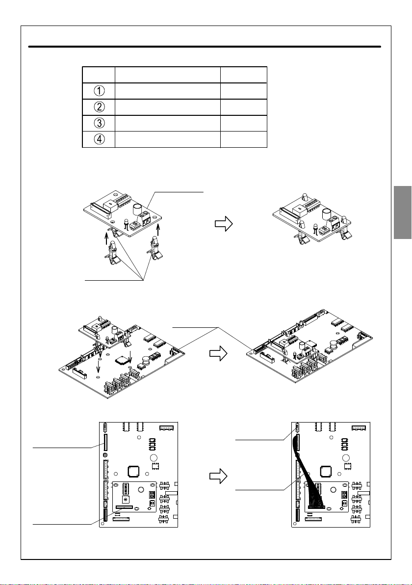
2. Installation der H-LINK-Platine
i. Montieren Sie die Platinenhalterung (3 Stck.) wie in der nachstehenden Abbildung
gezeigt in den Löchern der H-LINK-Platine.
ii. Stecken Sie die H-LINK-Platine in die HAUPT-Platine ein (verwenden Sie die 3 Löcher
an der HAUPT-Platine, die für die Aufnahme der H-LINK-Platine vorgesehen sind).
iii. Schließen Sie das 14-polige Kabel an CN28 der H-LINK-Platine und CN1026 der
HAUPT-Platine an.
H-LINK-Platine
Platinenhalterung
Anschluss CN1026
der HAUPT-Platine
Anschluss CN28
der H-LINK-Platine
14-poliges Kabel
iv. Stellen Sie den SW1301 der HAUPT-Platine vor dem Start des H-LINK-Betriebs in die
Stellung ON (werkseitige Standardstellung ist OFF).
SW1301 der
HAUPT-Platine
HAUPT-Platine
DEUTSCH

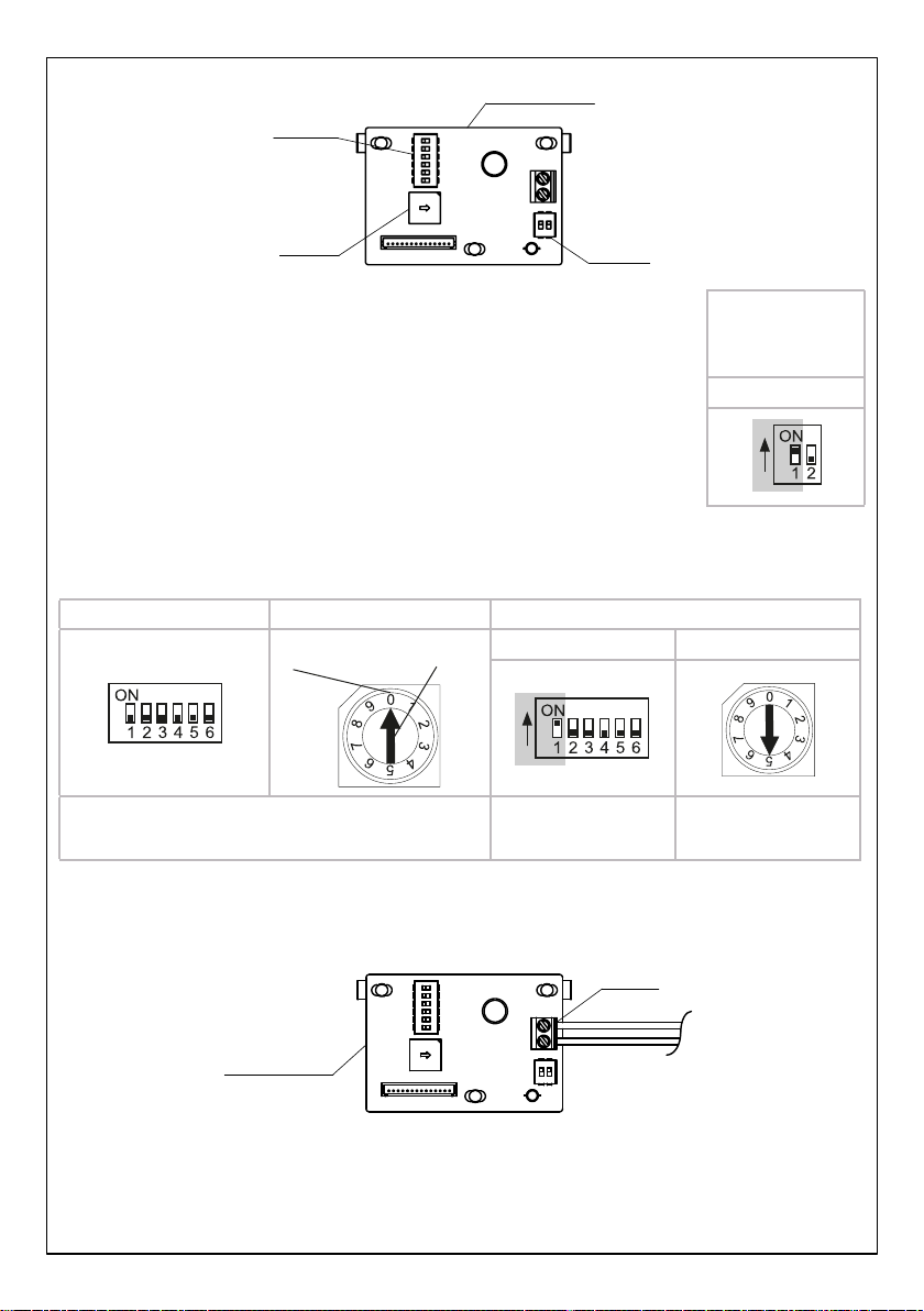
3. DIP-Schaltereinstellung. H-LINK-Platine
DSW1
DSW2
RSW1
i. DSW1-Einstellung (Einstellung des Abschlusswiderstands).
Einstellung des Abschlusswiderstands über PIN 1 des DSW1.
(Die werkseitige Einstellung ist PIN 1 des DSW1 eingestellt in
Stellung OFF).
Der Anschlusswiderstand sollte nur an einer Position des gesamten
H-LINK eingeschaltet sein.
Nach Überprüfung der Einstellung des Abschlusswiderstands des
gesamten H-LINK muss PIN 1 des DSW1 korrekt eingestellt sein.
ii. Einstellung von DSW2 und RSW1.
Die Kühlkreislaufnummer wird durch DSW2 und RSW1 eingestellt.
DSW2 (Zehnerstellen) RSW1 (Einerstelle) Beispiel: Einstellung der Kreislaufnummer auf 15
Einstellen durch Einstecken
eines Schraubendrehers
Position
DSW2 RSW1
Die werkseitigen Einstellungen für DSW2 und RSW1
sind OFF bzw. 0. PIN 1 ist ON Die Position ist auf
5 gestellt
4. Schließen Sie die H-LINK-Platine an der Zentraleinheit an, indem Sie das
Übertragungskabel am CN29 anbringen.
H-Link-Platine
CN29
Das verwendete Übertragungskabel muss wie unten beschrieben sein.
i. 2 zweiadrige Kabel (0,75 mm2bis 1,25 mm2). Modell: VCTF, VCT, CVV, MVVS,
CVVS VVR, VVF.
ii. 2 zweiadrige Twisted-Pair-Kabel. Modell: KPEV, KPEV-S.
Die Gesamtlänge des Übertragungskabels darf 1000 m nicht überschreiten.
Übertragungskabel
zur Zentraleinheit
DSW1
Beispiel:
Bei Einstellung des PIN 1
in die Stellung ON
Opmerking: Het nummer van de binnenunit wordt automatisch door de buitenunit
geadresseerd.

Manuel d’installation de la carte H-LINK (SPX-RAMHLK)
1. Contrôlez les accessoires de la carte H-LINK.
Tableau 1 N° Nom de la pièce Quantité
1
3
1
1
Carte H-LINK
Support de carte
Câble 14 broches
Manuel d’installation
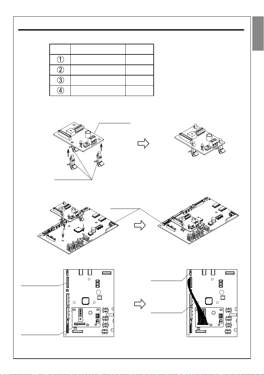
2. Installez la carte H-LINK.
i. Assemblez le support de carte (3 pièces) dans les trous de la carte H-LINK comme
indiqué dans l’illustration suivante.
ii. Insérez la carte H-LINK dans la carte MÈRE (les trois trous de la carte MÈRE sont
conçus pour s’adapter à la carte H-LINK).
iii. Insérez le câble 14 broches dans le connecteur CN28 de la carte H-LINK et le
connecteur CN1026 de la carte MÈRE.
Carte H-LINK
Support de carte
Connecteur CN1026
de la carte MÈRE
Connecteur CN28
de la carte H-LINK
Câble 14 broches
iv. Réglez le connecteur SW1301 de la carte MÈRE sur ON avant de mettre la carte
H-LINK en fonction (par défaut, le connecteur est réglé sur OFF en usine).
Connecteur SW1301
de la carte MÈRE
Carte MÈRE
FRANÇAIS
3. Réglez le commutateur DIP. Carte H-LINK
DSW1
DSW2
RSW1
i. Réglage du DSW1 (résistance de la borne d’attache)
Réglage de la résistance de la borne d’attache sur la broche n° 1 de
DSW1.
(La broche n° 1 de DSW1 est par défaut réglée sur la condition OFF
en usine).
La résistance de la borne d’attache doit être branchée sur une seule
position pour l’ensemble de la carte H-LINK.
Après avoir vérifié le réglage de la résistance aux bornes de
l’ensemble de la carte H-LINK, la broche n° 1 du DSW1 doit être
réglée correctement.
ii. Réglage de DSW2 et de RSW1
Le numéro du cycle frigorifique est déterminé par DSW2 et RSW1.
DSW2 (chiffre des dizaines) RSW1 (chiffre des unités) Exemple : Réglage du numéro du cycle sur 15
Réglez-le en insérant
un tournevis.
Position
DSW2 RSW1
Par défaut, DSW2 et RSW1 sont réglés en usine sur OFF
et 0 respectivement.
La branche n° 1 est
réglée sur ON
La position de
réglage est 5
4. Connectez la carte H-LINK à la commande centralisée en fixant le câble de transmission
au connecteur CN29.
Carte H-LINK
CN29
Le câble de transmission utilisé doit présenter les caractéristiques suivantes.
i. Câble 2 brins (0,75 mm2à 1,25 mm2). Modèle : VCTF, VCT, CVV, MVVS, CVVS VVR,
VVF.
ii. Câble blindé à paire torsadée 2 brins. Modèle : KPEV, KPEV-S.
La longueur totale du câble de transmission ne doit pas être supérieure à 1000 m.
Câble de transmission
de la commande
centralisée
DSW1
Exemple :
Si la broche n° 1
est réglée sur la
condition ON
Remarque: Les adresses des unités intérieures sont déterminées automatiquement en
fonction du port de connexion sur le groupe extérieur.
Manuale di installazione scheda H-LINK (SPX-RAMHLK)
1. Verificare gli accessori della scheda H-LINK.
Tabella 1 No Nome del componente Quantità
1
3
1
1
Scheda H-LINK
Supporto scheda
Cavo 14 pin
Manuale di installazione
2. Installazione scheda H-LINK
i. Montare il supporto scheda (3 pz) sui fori della scheda H-LINK come mostrato in figura.
ii. Inserire la scheda H-LINK nella scheda MAIN (utilizzare 3 fori sulla scheda MAIN
progettati per stare nella scheda H-LINK).
iii. Inserire il cavo 14 pin nel CN28 della scheda H-LINK e CN1026 della scheda MAIN.
Scheda H-LINK
Supporto scheda
Connettore
CN1026 della
scheda MAIN
Connettore
CN28 della
scheda H-LINK
Cavo 14 pin
iv. Impostare il SW1301 della scheda MAIN in condizione ON prima di avviare H-LINK
(la posizione predefinita di fabbrica è condizione OFF).
SW1301 sulla
scheda MAIN
Scheda MAIN
ITALIANO

3. Impostazione interruttore DIP. Scheda H-LINK
DSW1
DSW2
RSW1
i. Impostazione DSW1 (impostazione resistenza morsetti finali).
Resistenza morsetti finali impostata da pin numero 1 di DSW1.
(L'impostazione predefinita in fabbrica è pin numero 1 di DSW1
impostato in condizione OFF).
La resistenza dei morsetti finali deve essere attivata solo in una
posizione in tutto H-LINK.
Dopo aver verificato l'impostazione della resistenza dei morsetti
finali di tutto H-LINK, il pin numero 1 di DSW1 deve essere
impostato correttamente.
ii. Impostazione di DSW2 e RSW1.
Il numero del ciclo di refrigerazione è impostato da DSW2 e RSW1.
DSW2 (dieci cifre) RSW1 (una cifra) Esempio: Impostazione del numero del ciclo a 15
Impostarlo inserendo
un cacciavitePosizione
DSW2 RSW1
Le impostazioni predefinite di fabbrica sono OFF e 0
rispettivamente per DSW2 e RSW1. Pin numero 1 è ON La posizione
impostata è 5
4. Collegare la scheda H-LINK alla postazione centrale fissando il cavo di trasmissione
a CN29.
Scheda H-Link
CN29
Il cavo di trasmissione utilizzato deve essere come segue.
i. Cavo a 2 anime (da 0,75 mm2a 1,25 mm2). Modello: VCTF, VCT, CVV, MVVS,
CVVS VVR, VVF.
ii. Cavo a 2 anime ritorto. Modello: KPEV, KPEV-S.
La lunghezza totale del cavo di trasmissione deve essere inferiore ai 1000 m.
Cavo di trasmissione
alla postazione centrale
DSW1
Esempio:
se il pin numero 1
è impostato in
condizione ON
Nota: L'indirizzamento delle unità interne viene eseguito automaticamente dalla unità
esterna
H-LINK Board (SPX-RAMHLK) Installation Manual
1. Check through H-LINK board accessories.
Table 1 No Part Name Quantity
1
3
1
1
H-LINK board
Board support
14 pin cord
Installation manual
2. H-LINK board installation
i. Assemble board support (3 pcs) to H-LINK board holes as following picture.
ii. Insert the H-LINK board into the MAIN board (please use 3 holes on MAIN board that
designed to fit the H-LINK board).
iii. Insert the 14 pin cord to the CN28 of the H-LINK board and CN1026 of the MAIN board.
H-LINK board
Board support
Connector
CN1026 of the
MAIN board
Connector
CN28 of the
H-LINK board
14 pin cord
iv. Set the SW1301 of the MAIN board to ON condition before start the H-LINK operation
(default position from factory is OFF condition).
SW1301 of the
MAIN board
MAIN board
ENGLISH

3. DIP switch setting. H-LINK board
DSW1
DSW2
RSW1
i. DSW1 setting (terminal resistance setting).
Terminal resistance setting set by pin number 1 of DSW1.
(Default setting from factory is pin number 1 of DSW1 set to OFF
condition).
Terminal resistance should be ON in only one position in whole H-LINK.
After checking terminal resistance setting of whole H-LINK, pin number
1 of DSW1 should be set properly.
ii. DSW2 and RSW1 setting.
Refrigerant cycle number is set by DSW2 and RSW1.
DSW2 (tens digit) RSW1 (ones digit) Example: Setting cycle number to 15
Set it inserting a
screwdriver
Position
DSW2 RSW1
Default setting from factory for DSW2 and RSW1
are set to OFF and 0 respectively. Pin number 1 is ON The set position is 5
4. Connect the H-LINK board to the Central Station by fixing the transmision cable at CN29.
H-Link board
CN29
The transmission cable used shall be as below.
i. 2 cores cable (0.75mm2to 1.25mm2). Model : VCTF, VCT, CVV, MVVS, CVVS VVR, VVF.
ii. 2 cores twist pair cable. Model : KPEV, KPEV-S.
Total length of the transmission cable shall be below than 1000m.
Transmission cable
to Central Station
DSW1
Example:
If set pin number 1
to ON condition
Note: Indoor unit number will be addressed by outdoor unit automatically.
Table of contents
Languages:


