Charles 3608-80 Secondary T1 User manual

Section 360-880-202
Equipment Issue 2
Third Printing, August 2006Telecommunications Group
2006 Charles Industries Ltd.
All rights reserved. Printed in United States of America.
The availability of features and technical specifications herein subject to change without notice.
Page 1 of 18
3608-80 Secondary T1 Unit
CONTENTS PAGE
Part 1. GENERAL 2. . . . . . . . . . . . . . . . . . . . . . . . . . . . . . . . . . . . . . . . . . . . . . . . . . . . . . . . . . . . . . . . . . . . . . . . . . . . .
Part 2. INSPECTION 3. . . . . . . . . . . . . . . . . . . . . . . . . . . . . . . . . . . . . . . . . . . . . . . . . . . . . . . . . . . . . . . . . . . . . . . . . . .
Part 3. APPLICATION GUIDELINES 4. . . . . . . . . . . . . . . . . . . . . . . . . . . . . . . . . . . . . . . . . . . . . . . . . . . . . . . . . . . . .
Part 4. CIRCUIT DESCRIPTION 7. . . . . . . . . . . . . . . . . . . . . . . . . . . . . . . . . . . . . . . . . . . . . . . . . . . . . . . . . . . . . . . . .
Part 5. INSTALLATION 12. . . . . . . . . . . . . . . . . . . . . . . . . . . . . . . . . . . . . . . . . . . . . . . . . . . . . . . . . . . . . . . . . . . . . . . .
Part 6. OPTIONING 15. . . . . . . . . . . . . . . . . . . . . . . . . . . . . . . . . . . . . . . . . . . . . . . . . . . . . . . . . . . . . . . . . . . . . . . . . . .
Part 7. ALARMS 15. . . . . . . . . . . . . . . . . . . . . . . . . . . . . . . . . . . . . . . . . . . . . . . . . . . . . . . . . . . . . . . . . . . . . . . . . . . . .
Part 8. TECHNICAL ASSISTANCE 15. . . . . . . . . . . . . . . . . . . . . . . . . . . . . . . . . . . . . . . . . . . . . . . . . . . . . . . . . . . . .
Part 9. WARRANTY & CUSTOMER SERVICE 16. . . . . . . . . . . . . . . . . . . . . . . . . . . . . . . . . . . . . . . . . . . . . . . . . . .
Part 10. SPECIFICATIONS 17. . . . . . . . . . . . . . . . . . . . . . . . . . . . . . . . . . . . . . . . . . . . . . . . . . . . . . . . . . . . . . . . . . . . .
SEC
3608−80
AR AY
TP LP
MON
RCV XMT ACO PWR
+
BYPASS
T1
Figure 1. 3608-80 T1 Secondary Unit Front Panel

Section 360-880-202
2
1. GENERAL
1.1 Document Purpose
This document provides general, installation and testing information for the Secondary T1 Unit (ST1U), shown in
Figure 1. This document covers model number 3608-80.
1.2 Document Status
This document is reprinted to add additional features (”Dual” and “Protection” T1 modes).
1.3 Equipment Function
The ST1U is part of the 360-80 Intelligent Channel Bank (ICB). It combines the functions of a line interface unit
(LIU) and a channel service unit (CSU), allowing direct connections to public T1 networks. The ST1U is a secon-
dary T1 unit for the ICB, providing normal/drop and re-insert (D&RI), dual T1 mode and protection mode when
used with the T1 controller with SNMP (T1-S).
1.4 Equipment Location/Mounting
Mount the ST1U in the secondary (half-size) slot of the 360-80. One T1-S controller unit (issue 2 or later) must be
installed in the primary slot for proper system operation.
Note: This unit must be mounted in an issue 3 or later 360-80 shelf.
1.5 Equipment Features
This unit provides the following features:
Downstream data blocking or broadcast for dropped timeslots (normal/D&RI mode only).
Independent T1 loop timing (dual T1 mode only).
Transport Protection switching (protection mode only).
Drop and re-insert operation with bypass (normal/D&RI mode only).
Front panel status LEDs.
Front panel T1 monitor jacks.
Time slot assignment on a per-channel basis.
Auto framing and identification (SF or ESF).
Auto line coding and identification (AMI or B8ZS).
Hot unit insertion or extraction.
24-channel T1 multiplexing operation (up to 48 channels in dual T1 or D &RI modes).
Temperature hardened (−40 to +65 C).
Combines the functions of a LIU and a CSU, allowing direct connections to public T1 networks.
Operates in either superframe (SF) or extended superframe (ESF) mode, uses AMI or B8ZS line
coding, & performs all loopback, test & performance monitoring of the T1 interface (local & remote).
UL/CSA listed and FCC verified.
Meets Bellcore 1089, 43801, 62411, 54016, TR-57 and ANSI T1.403 standards for T1.
1.6 Performance History
This unit stores performance history for the last 30 days in 24-hour intervals and over the last 24 hours in 15-min-
ute intervals. This performance history includes failed seconds, errored seconds and severely errored seconds
(per T1M1.3/93-00). The current 15-minute interval can be reset or the current 24-hour interval can be reset.
When the current 24-hour interval is reset all 15-minute intervals within those 24 hours are reset.

Section 360-880-202
3
1.7 Control Interface
This unit is managed through the craft port, the Network Management Software (NMS), or an SNMP Network
Node Manager (NNM) which controls the provisioning of the unit and obtains status information from the unit.
Provisioning is described in the Optioning section of this document. For operation, see the craft port, NMS or
NNM documentation.
This unit will maintain its default provisioning until that provisioning is altered through the control interface. If this
unit’s provisioning is changed, it will maintain the new provisioning even if power is lost. If replaced with a new
unit, the new unit will default to the same provisioning as was set for the prior unit. If this unit is installed in a loca-
tion that was used by a different type of unit, such as a 6 channel half size card, it will use its own default provi-
sioning.
1.8 Status Indicators
This unit is able to provide a variety of status information. The following is a list of all status information available
from the ST1U. Some status information is also provided through front panel LEDs. See individual channel units
for additional status information.
Red (AR) Alarm Status (LED)
Yellow (AY) Alarm Status (LED)
Loss of frame (LOF) Alarm Status
Loss of signal (LOS) Alarm Status
Power status (LED)
T1 framing selected
Line code
Trunk processing (TP) status (LED)
Line build out selected
T1 loopback selected (LED)
T1 bypass active LED (for normal/D&RI mode only)
2. INSPECTION
2.1 Inspect for Damages
Inspect the equipment thoroughly upon delivery. If the equipment has been damaged in transit, immediately re-
port the extent of damage to the transportation company.
2.2 Equipment Identification
Charles Industries’ equipment is identified by a model and issue number imprinted on the front panel or located
elsewhere on the equipment. Each time a major engineering design change is made on the equipment, the issue
number is advanced by 1 and imprinted on subsequent units manufactured. Therefore, be sure to include both
the model number and its issue number when making inquiries about the equipment.
2.3 Static Concerns
Each unit is shipped in static-protective packaging to prevent damages from electrostatic charges. Use approved
static-preventive measures, such as static-conductive wrist straps and a static-dissipative mat, when handling
units outside of their protective packaging. A unit intended for future use should be tested as soon as possible
and returned to its original protective packaging for storage.

Section 360-880-202
4
STATIC-SENSITIVE
This equipment contains static-sensitive electronic devices. To prevent electrostatic charges from
damaging static-sensitive units:
Use approved static-preventive measures (such as static-conductive wrist straps and static-dissipa-
tive mats) at all times whenever touching units outside of their original, shipped, protective packaging.
Do not ship or store units near strong electrostatic, electromagnetic, or magnetic fields.
Always use the original static-protective packaging for shipping or storage. Return a tested unit to its
original protective packaging for storage.
3. APPLICATION GUIDELINES
The ST1U is used only in the 360-80 ICB. Using the 3608-80 ST1U in any other Charles product will cause im-
proper operation and could damage the equipment.
Note: When using HDSL modules for T1 transport, you may experience some problems with communication
using the T1 facility data link (embedded operations channel) due to the T1 to DSL conversion/synchro-
nization process.
3.1 Dual T1 Mode Applications
3.1.1. Independent Dual T1 Application
The Dual T1 mode allows the T1 of the T1-S and the T1 of the ST1U to be connected to two different 360-80
ICBs. These two T1s run independently of each other and allow the 360-80 system to provide up to 1.5 Mbps to
each T1 for a total of over 3 Mbps of bandwidth. See Figure 2 for a typical configuration.
In this configuration there are two different possible timing scenarios:
1. The 360-80 (A) in internal/external timing with the 360-80 (B) and the 360-80 (C) in loop timing.
2. Both the 360-80 (B) and the 360-80 (C) in internal/external timing with the 360-80 (A) in loop timing.
For network management of multiple 360-80s over the T1 links, connecting the management LAN to the 360-80
(B) will provide the capability to manage the 360-80 (A) and 360-80 (C) systems. Similarly, management connect-
ing the management LAN to the 360-80 (A) will provide the capability to manage the 360-80 (B) and 360-80 (C)
systems. However, when connecting the management LAN to the 360-80 (C) only 360-80 (C) can be managed.
Primary
360-80 (A)
360-80 (B)
360-80 (C)
T1-S
ST1U
T1
Secondary
T1
Figure 2. Independent Dual T1 Application
3.1.2. Combined Dual T1 Application
The dual T1 mode allows over 3 Mbps of data to be transported between two 360-80 systems over two T1s (be-
cause of physical constraints, a 64xN or router unit would be required to use the complete bandwidth). See
Figure 3 for the configuration.

Section 360-880-202
5
360-80
Primary
Secondary
360-80
T1-S
ST1U
ST1U
T1-S
T1
T1
Figure 3. Combined Dual T1 Application
3.2 Transport Protection Application
The Protection mode allows the Primary T1 of the T1-S and the Protection T1 of the ST1U to be connected to a
remote 360-80 or an Automatic Protection Switch (APS) device. The Primary T1 from the T1-S is used as the T1
carrier when no fault or excessive bit error rates are detected by the system. If the Primary T1 error rate exceeds
an errored second threshold or a fault is detected in the primary T1, the system will switch to the T1 from the
ST1U (the Protection T1) as the T1 carrier. The Protection T1 will continue to be used until the Primary T1 error
rate improves or the alarm condition is cleared. The system will monitor the errored seconds in the current and
previous performance monitor interval to determine if the system should switch to the protection mode. See
Figure 4 for a typical configuration.
Note: Both T1-S units should be set for the same error threshold.
360-80
Primary
T1
360-80
T1
Protection
T1-S
ST1U
T1-S
ST1U
Figure 4. T1 Transport Protection Application
3.3 Drop and Re-Insert Applications
“Normal” mode allows the T1 from the T1-S to be connected via the ST1U to a channel bank from the network
(west) and the T1 from the ST1U to be connected to a channel bank toward a remote (east) location. The data/
voice on the Primary T1 (which is connected through the ST1U to the T1-S) can be “dropped” to any one of the
cards in the 360-80. Any data/voice that is not “dropped” to a card in the 360-80 can be reinserted into the T1
from the ST1U and sent to the remote location. See Figure 5 for an application where the 360-80 is used to
“drop” dedicated circuits from a T1 and then send the switched voice over a T1 to a PBX.
Local PBX
T−1 Trunk
360-80 ICB
T1
Full T1 facility @ 1.544
MB/s “800” service
trunks and data
“800” service trunks
Drop and re-insert data channels to data equipment
Figure 5. Drop and Re-Insert Application #1

Section 360-880-202
6
Additionally, data/voice from cards in the 360-80 can be “re-inserted” into any vacant timeslots to the remote loca-
tion. This allows better use of the T1 timeslots by keeping them as full as possible between locations. See
Figure 6 for an application where the 360-80 is used to “drop” channels and re-insert channels from multiple loca-
tions to reduce the number of T1s needed between locations by keeping the T1 full. If a fault occurs in the 360-80
system, the T1 into the T1-S is connected to the T1 into the ST1U, bypassing the 360-80 system.
1
2
3
4
23
24
Terminal MUX
24
Channels 16
Channels 16
Channels
“Drop & Re-Insert”
8 channels west
and 8 channels east
“Drop & Re-Insert” 16 channels
“Terminate”
360-80 ICB 360-80 ICB 360-80 ICB
ABC
“West”
“East”
Site 1 Site 2
8 channels west
Figure 6. Drop and Re-Insert Application #2
Another configuration that can use the drop and re-insert capability allows the system to handle more than 2
types of circuits at a location. In this configuration, the drop and re-insert capability is used to combine the card
types in multiple 360-80s at a single location to allow more card types at the location. Each bank has a different
card type to allow more interfaces to be serviced at the location. This allows flexibility when customer require-
ments change.
8 Channels
Incoming
T1/DS1
8 Channels
8 Channels
360-80 ICB
360-80 ICB
360-80 ICB
24 channels
16 channels
8 channels
Figure 7. Drop and ReInsert Application #3

Section 360-880-202
7
4. CIRCUIT DESCRIPTION
Figure 8 shows a block diagram of the ST1U, and its relationship to other elements of the 360-80 ICB.
4.1 Normal (Drop and Re-Insert) Mode Configuration
The T1-S provides the centralized control, multiplexing and test features for the 360-80 ICB. T1 signals from and
to the WEST (primary T1) direction are first routed through the ST1U to the T1-S. The ST1U uses timing from the
T1-S and must be loop timed to the WEST to operate correctly.
T1 signals from and to the EAST (secondary T1) direction are routed to the ST1U. The ST1U includes a monitor
jack access to the T1.
The ST1U provides a bypass relay path for the T1 facility as part of the assembly, as shown in Figure 8. When
de-energized, these relays bypass the ICB and connect the WEST (primary) T1 to the EAST (secondary) T1.
When the ST1U and T1-S are installed and functioning properly, these relays are energized. Figure 8 shows the
relay contacts in this mode. If either of these modules fail or the T1-S is removed, the relay will release and by-
pass the T1. The ST1U can also be manually selected to bypass the T1.
The ST1U provides various front panel indicators to monitor operation .
X
M
T
R
C
V
MON
WEST
PROTECTION
BYPASS
CONTROL
X
X
X
X
X
X
X
X
EAST
TIMING &
FRAMING
TIMESLOT
CONTROL
CABLE
TO
T1-S
VOICE & DATA CIRCUITS
T1 (J6)
PRIMARY
During normal operation bypass,
relay is energized as shown.
EAST
T1 (J4)
SECONDARY
(J5)
T1-S
T1-S
BYPASS
CIRCUIT
Figure 8. Secondary T1 Unit Block Diagram

Section 360-880-202
8
4.1.1. Transmission Path, WEST RCV to EAST XMT (Normal Mode Only)
T1 signals received from the WEST facility (J6) pass through the ST1U bypass circuit, through the rear-panel
connection (J5), into the T1-S. The information, in DS0 timeslots that are dropped at this location, can be provi-
sioned to pass (through an internal circuit) on to the T1 on the ST1U (Broadcast) or replaced with idle code.
Timeslots that are not dropped at this location can be passed through, unaltered, to the ST1U and transmitted
EAST (J4). Timeslots that have been dropped can be reassigned for use towards the EAST.
The ST1U formats the timeslot data and insert either SF or ESF framing. The data is then output to the EAST T1
connector.
4.1.2. Transmission Path, EAST RCV to WEST XMT (Normal Mode Only)
T1 signals received from the EAST (secondary) facility are routed to the ST1U’s monitor jack and to the EAST
TIMING & FRAMING circuit. This circuit detects either SF or ESF framing. A loss of signal or framing will cause
the AR LED to illuminate and start the alarm processing routine. The framed DS1 signal is passed on to the
TIMESLOT CONTROL circuit. Any DS0 channel timeslot that has been provisioned to be dropped from the
WEST will have its transmit data blocked toward the WEST from the EAST T1 receive data. These EAST T1 re-
ceive timeslots can be dropped from the EAST or left unassigned. EAST T1 receive timeslots that are not
dropped at this location are passed through unchanged to the WEST facility. Dropped EAST T1 receive timeslots
that are not blocked toward the WEST, due to the WEST receive T1 timeslot being dropped, may use the time-
slot mode’s broadcast option. This option allows timeslot data to be dropped and retransmitted toward the WEST.
The channel data at this location is reinserted by the TIMESLOT CONTROL toward the WEST.
4.2 Dual T1 Mode Configuration
In this configuration, the T1 signal for the ST1U is to and from the EAST (secondary T1, J4). The ST1U provides
monitor jacks to monitor this T1. The T1 then goes to the EAST TIMING and FRAMING block where the circuit
detects either SF or ESF framing. A loss of framing signal will cause the AR LED to light and start the alarm proc-
essing routine. The signal is passed on to the TIMESLOT CONTROL circuit. Any DS0 channel that has been pro-
visioned to a Secondary T1 timeslot will receive its data and timing from the TIMESLOT CONTROL circuit.
In a similar manner, data from the channel cards is sent to the TIMESLOT CONTROL circuit where it is multi-
plexed with the data from the other channel circuits. The data is then passed to the EAST TIMING and CON-
TROL circuit where framing is inserted and then output to the EAST T1 connector.
4.3 Protection T1 Mode Configuration
In this configuration, the T1 signal for the ST1U is to and from the EAST (protection/secondary T1, J4). The
ST1U provides monitor jacks to monitor this T1. The T1 then goes to the EAST TIMING and FRAMING block
where the circuit detects either SF or ESF framing. A loss of framing signal will cause the AR LED to light and
start the alarm processing routine. The signal is passed on to the TIMESLOT CONTROL circuit. If no alarm con-
dition exists or the errored seconds are acceptable, the DS0 channels will receive their data from the T1-S.
In a similar manner, data from the channel cards is sent to the TIMESLOT CONTROL circuit where it is multi-
plexed with the data from the other channel circuits. The data is then passed to the EAST TIMING and CON-
TROL circuit where framing is inserted and then output to the EAST T1 connector. The alarm condition of the T1
Controller card has no effect on this output.
4.4 Timeslot Allocation
The following rules apply when assigning or allocating timeslots to channels when using the ST1U in conjunction
with the T1−S:
Only non-allocated timeslots can be allocated to a channel (channel number is based on chassis slot
location and circuit number on card).
Only non-allocated channels can be allocated to a timeslot.
A timeslot/channel is de-allocated by selecting the channel and deleting its allocation.
Timeslots can only be allocated to a single channel (see Figure 9).

Section 360-880-202
9
When a channel uses multiple timeslots such as 64xN, ISDN and Router unit, there must be enough
consecutive timeslots to allow the channel to be allocated (an example is shown in Figure 9 where
channel 24 uses timeslots 22−24 on the primary T1).
For the Protection mode, only the 24 timeslots for the Primary T1 are allocated.
For the Dual and Normal modes there are 48 timeslots available for allocation (24 for Primary T1 and
24 for Secondary T1).
When the unit comes from the factory or a factory default reset is performed, all timeslots will be
allocated to the Primary T1 (similar to channels 1−5 in Figure 9).
When the unit comes from the factory or a factory default reset is performed and the unit is in Normal
mode and a chassis slot does not have a card installed; then the timeslots normally assigned to the
channels of the uninstalled card will be allocated to ‘phantom channels’. These timeslots must be
de-allocated before they can be allocated to a channel.
When a different card is inserted into a chassis slot that had timeslots allocated, the system will
attempt to allocate the timeslots to the card channels based on the card type.
Timeslot allocation can be done through any of the network management interfaces.
4.4.1. Changing Channels/Timeslots
Any channel can be assigned to any timeslot. Using Figure 9 as an example, if channel 16 were allocated to time-
slot 13 on the Primary T1, the following steps would be performed to change the allocation of channel 20 to time-
slot 13:
Step Action
1. De-allocate the current allocation by selecting channel 16 in the timeslot allocation section of the net-
work management interface and deleting its allocation.
2. Select channel 20 and allocate it to timeslot 13 of the Primary T1.
Primary T1
Timeslot
1 2 3 4 5 6 7 8 9 10 11 12 13 14 15 16 17 18 19 20 21 22 23 24
Channel 1 2 3 4 5 6 7 8 9 10 11 12 13 14 15 16 17 18 19 20 21 22 23 24

Section 360-880-202
10
Secondary T1
Timeslot
1 2 3 4 5 6 7 8 9 10 11 12 13 14 15 16 17 18 19 20 21 22 23 24
Figure 9. Timeslot Allocation with T1-S and ST1U
4.5 Timeslot Mode (Normal Mode Only)
The ST1U and T1-S use the timeslot mode to control the routing of data between T1-S and ST1U. The timeslot
mode can be set to idle or broadcast.
4.5.1. Timeslots Allocated on both Primary and Secondary T1 Circuits
When a timeslot from the primary T1 is allocated to a channel and the same timeslot on the secondary T1 is allo-
cated to another channel, the data is routed between the channels and the individual timeslot of the two T1s.
With this allocation the timeslot mode for both the primary and secondary T1s will be ignored. This allocation
mode is referred to as “Drop and Reinsert” because, the timeslot data is dropped and reinserted between one of
the T1s and the allocated channel. Data from a different channel is dropped and reinserted between the channel
and the same timeslot of the other T1.
Primary Secondary
W D/I E
Time Slot Mode has No Effect on Data in Both Directions
Figure 10. Drop at T1 Primary and Secondary for the Same Timeslot
4.5.2. Timeslot Allocated on the Primary T1 Circuit
When a timeslot from the primary T1 circuit is allocated to a channel, the timeslot mode of the primary T1 circuit
will be ignored and not affect the routing of the data. If the timeslot on the secondary T1 circuit is set for idle,
then the output data for the timeslot on the secondary T1 circuit will be an all ones (11111111) which equates to an
“idle” signal. If the timeslot on the secondary T1 circuit is set for broadcast, then the output data for that timeslot
of the secondary T1 circuit will be the same data that is received from the timeslot on the primary T1 circuit. This
allocation is called “Broadcast mode” because the data from the time slot on the primary T1 circuit is broadcast to
both the channel and the secondary T1 timeslot.
Primary Secondary
W D/I E
Controlled by Secondary T1 Time Slot Mode
Figure 11. Drop at T1 Primary with No Drop on Secondary

Section 360-880-202
11
4.5.3. Timeslot Allocated on the Secondary T1 Circuit
When a timeslot is allocated from the secondary T1 to a channel, the timeslot mode of the secondary T1 timeslot
is ignored and does not affect the data routing. Data is routed from the allocated channel to and from the time
slot on the secondary T1 circuit. If the timeslot on the primary T1 is set to idle, the output data for the timeslot on
the primary T1 will be an all ones (11111111) which equates to an “idle” signal. If the time slot on the primary T1 is
set to broadcast, then the output data on the primary T1 for the timeslot will be the same data that is sent from
the secondary T1 to the allocated channel. This allocation is called Broadcast mode because, the data from the
timeslot on the secondary T1 circuit is broadcast to the channel and to the primary T1 timeslot.
Primary Secondary
W D/I E
Controlled by Primary T1 Time Slot Mode
Figure 12. Drop at T1 Secondary with No Drop on Primary
4.5.4. Non-Allocated Timeslots
When a timeslot is not allocated to either the primary T1 circuit or the secondary T1 circuit, the primary and sec-
ondary timeslot mode determines the data output on the respective T1. If the mode is set to idle, the output of the
timeslot will be an all ones (11111111) which equates to an “idle” signal. If the mode is set to broadcast then the
output of the timeslot on the T1 will be the data from the corresponding time slot on the other T1. This allocation
mode is referred to as “Pass Through” because, when both primary and secondary timeslot modes are set to
broadcast the data passes through the 360-80.
Primary Secondary
W D/I E
Controlled by Secondary TS Mode
Controlled by Primary TS Mode
Figure 13. No Drop at T1 Primary or Secondary
4.6 Forced Bypass (Manually Selected via Management Normal Mode Only)
If this option is selected for an ICB, it will require local intervention at the site of the ICB to reset.
Restoring normal error free operation of the ICB will require a “reset” to return to stored values on a
local craft interface or Ethernet connection, or removing both the T1-S and ST1U. The cards must
then be reinserted in order, first the T1-S, followed by the ST1U.
WARNING
Card configuration is stored in an EEPROM so no additional settings adjustments are required.
4.7 Facility Alarm Handling
The alarm timing circuit provides the indications and timing for the trunk processing. Hit integration for Frame
Loss (FRL) is provided to prevent trunk processing during intermittent frame losses. LEDs are provided for local
red alarm (AR) and remote yellow alarm (AY).
The T1-S provides three optional trunk processing timing options (both primary and secondary T1s are configured
the same) that are selected via the NMS software. In the NORMAL position, the unit provides standard D4 timing.
In the CM2 & CM3 positions, special shortened timings are provided.
When a loss of signal or framing is detected on the WEST receive facility, a Red Alarm (AR) is declared and the
WEST AR LED is illuminated after 2.5 seconds (1 second if CM2 option is selected or immediately if the CM3
option is selected), and the unit will begin its trunk processing routine. This causes the following:

Section 360-880-202
12
1. All channel units are busied or idled
2. A yellow alarm (AY) condition is sent to the WEST transmit facility (if CM2 or CM3 is selected, a yel-
low alarm is not sent)
3. An AIS signal is sent to the EAST transmit facility on all unassigned channels going between EAST
and secondary
4. The alarm relay for the WEST AR and AY is activated
Trunk processing will end approximately 15 seconds (1 second for CM2, immediately for CM3) after detection of
no AR alarm condition.
When the WEST receive facility receives a yellow alarm condition from a distant terminal, the unit will declare a
yellow alarm and illuminate the AY LED after detecting this condition for approximately 480 ms. At this time, the
unit will begin its trunk processing routine that will:
1. Busy or idle all channel units
2. Send AIS code to the EAST transmit facility
3. Activate the alarm relay for the West AR and AY
Trunk processing will end approximately 30 ms after detection of no yellow alarm.
When a red alarm (AR) is detected on the East facility, a yellow alarm (AY) is sent back on the East facility. If a
yellow alarm is detected on the east facility, no other action is taken. Red or yellow alarms detected on the East
facility will illuminate the respective AR and/or AY LEDs. When the red alarm condition no longer exists for
approximately 15 seconds, the yellow alarm signal will stop being sent. If no yellow or red alarm conditions are
detected, the LEDs will turn off.
4.8 Loopbacks
The ST1U provides three different types of loopbacks. All of the far-end loopbacks require a remote control link
between the near-end and far-end 360-80s. The line near-end loops the data back toward the customer of drop-
side. Far-end loopbacks can be either payload or line. The far-end payload loopback will loopback only the time
slots in the T1, but not the framing. The far-end line loopback will loopback all timeslots and the framing of the T1.
The card also responds to all standard CSU and T1 loopback codes.
5. INSTALLATION
5.1 Installing the Unit
The ST1U installs in the secondary T1 slot of the 360-80. See Figure 14 for a sample of the shelf layout.
Multichannel Unit Multichannel Unit
Primary T1 Controller (T1-S)
(channels 13−24)
(channels 1−12)
(channels 25−30)
Multichannel Unit
or Secondary T1
Unit
Figure 14. 360-80 ICB Common Equipment Configuration
5.1.1. Attaching the Rear Panel
The rear panel of the unit should be installed before the unit is installed in the shelf, and before wiring begins.

Section 360-880-202
13
J6J5
J4
++
SEC T1/EAST T1CU PRI T1/WEST
Figure 15. 3608-80 ST1U Rear Panel
5.1.2. Installing a New Unit
Use the following steps to install the ST1U.
Step Action
1. If not already installed, install the rear panel, screwing it to the appropriate mounting locations on the
shelf using the provided hardware.
WARNING: If there is already a rear panel installed on the shelf, check for interference when
mounting. The rear panel may need to be removed and replaced with the rear panel that has
been shipped with the new unit.
2. Insert the unit into the shelf, making sure that the unit is aligned with the card guides inside the shelf.
3. Slide the unit fully into the shelf. Use the insertion lever to fully seat the unit.
4. Once the unit is fully inserted, tighten the securing screw on the front panel of the unit.
5. Wire the unit per the wiring information in the wiring section.
When power is applied, the unit will perform a self-test to ensure that it is compatible with the network
management software on the system.
6. After the self-test is performed, check the software provisioning of the unit using either the front panel
craft interface on the front of the controller unit or the network management interface on the rear of the
controller (see the section on network management for more information on this interface).
Note: If a Secondary T1 unit is inserted into a shelf while power to the shelf is on, the T1 controller
unit may reset.
5.1.3. Installing a Replacement Unit
If you are replacing a unit that is already in service, insure that the new unit is the same as the unit being re-
placed.
Step Action
1. Remove the wiring connectors from the front and rear of the unit (J4, J5 & J6).
2. Unscrew the front panel securing screw to release the unit from the shelf.
3. Using the card ejector, remove the unit from the shelf.
4. Follow the procedure for installing a new unit.
5.2 Wiring the Unit
5.2.1. Drop and Re-Insert Application
Use the following steps to wire the unit (see Figure 16).
Step Action
1. Connect the T1 from the WEST 360-80 ICB or equivalent to J6 of the ST1U.
2. Using the cable provided with the unit, connect J5 to J1 on the T1-S.
3. Connect J4 of the ST1U to the input of the next 360-80 ICB or to the EAST 360-80 ICB or equivalent.

Section 360-880-202
14
3608−80 Rear View 3608−80 Rear View
TI-S
STIU
STIU
TI-S
TI-S
WEST EAST
A
A
DS1/T1 toward network
Figure 16. Wiring for Drop and Re-Insert Application
5.2.2. Dual and Protection Applications
Use the following steps to wire the unit (see Figure 17).
Step Action
1. Connect the T1 from the WEST 360-80 ICB or equivalent to J1 of the T1-S.
2. Connect J4 of the ST1U to the input of the EAST 360-80 ICB or equivalent
3608−80 Rear View
STIU
TI-S
WEST/PRIMARY
A
A
DS1/T1
A
A
PROTECTION T1 OR
SECONDARY DS1/T1
Figure 17. Wiring for Dual and Protection Applications
5.3 Front Panel Switch and LED Definitions
The Audible Alarm Cut Off (ACO) switch is a pushbutton used to open the audible alarm contacts from the
360-80 system. This switch will only mask audible indications of present alarm conditions—it does NOT clear the
alarm. If a new alarm occurs, the audible indication will re-enable.
Table 1. LED Definitions
Label Color Indicates that...
POWER Green The unit is receiving power
AR Red The unit is detecting a red alarm on the T1 interface caused by a loss of signal (LOS)
or a loss of framing (LOF) or out of frame (OOF) condition.
AY Yellow The unit is receiving a YELLOW alarm condition on the T1. This indicates that a prob-
lem is upstream at some other device or network node.
TP Yellow The system is processing the trunk signaling data based on detected alarm conditions.
LP Green The unit is in a loopback condition. This indication only occurs during testing.
BYPASS Green The unit is in a bypass condition.
5.4 Connector Definitions
5.4.1. Bantam Jacks
The two bantam jacks on the front of the unit allow monitoring of the transmit (XMT) and receive (RCV) sides of
the secondary T1 signal without interfering with operation.

Section 360-880-202
15
5.4.2. T1 Jacks
The RJ48 connectors on the rear of the ST1U are for the T1-S, east/secondary T1 and west/primary T1.
Table 2. RJ-48C T1 Jack Pinouts
Pin # Use
1R (RCV from network)
12345678
2T (RCV from network)
1
2
3
4
5
6
7
8
3 —
4R1 (XMIT to network)
5T1 (XMIT to network)
6 —
7 —
8 —
6. OPTIONING
This unit comes from the factory with default provisioning, which can be changed through the Network Manage-
ment software (NMS) or the craft terminal interface. See the NMS or craft terminal interface documentation for
procedures. The provisioning options are as follows with the default optioning noted:
Option Choices Default
T1 Frame format Superframe (SF), Extended Superframe (ESF) ESF
Line Build Out (LBO) 110, 220, 330, 440, 550, 660 ft. OR 0, 7.5, 15, 22dB 0-110 ft.
T1 Line Code AMI, B8ZS B8ZS
T1 Loopback Selection Line Near End, Line Far End, Payload Far End None
Remote Control Method None, Occupy One Channel, Facility Data Link (ESF
Format Only)
Facility Data Link
Bypass (Drop and Re-insert
Only)
Auto Bypass, Forced No Bypass Auto Bypass
7. ALARMS
This unit provides for alarm contacts for audible and visual alarms. Access to the alarm contacts is provided on
the 360-80 shelf. Pressing the audible alarm cut-off (ACO) switch on the ST1U clears the secondary alarm indica-
tion for the audible alarm contacts, stopping the audible notice of the alarm (the alarm itself is NOT cleared by
pressing the ACO switch). See the shelf documentation for information on wiring. The unit generates alarm indi-
cations based on the configuration of the PRI T1 alarm registers (Normal, CM2, CM3). See section on network
management for more information.
8. TECHNICAL ASSISTANCE
If technical assistance is required, contact Charles Industries’ Technical Services Center at:
847-806-8500
847-806-8556 (FAX)
800-607-8500
[email protected] (e-mail)

Section 360-880-202
16
9. WARRANTY & CUSTOMER SERVICE
9.1 Warranty
Charles Industries, Ltd. offers a 2-year warranty on this product. Contact your local Sales Representative at the
address or telephone numbers below for warranty details. The warranty provisions are subject to change without
notice. The terms and conditions applicable to any specific sale of product shall be defined in the resulting sales
contract.
Charles Industries, Ltd.
5600 Apollo Drive
Rolling Meadows, Illinois 60008-4049
847-806-6300 (Main Office)
847-806-6231 (FAX)
9.2 Field Repairs (In-Warranty Units)
Field repairs involving the replacement of components within a unit are not recommended and may void the war-
ranty and compatibility with any applicable regulatory or agency requirements. If a unit needs repair, contact
Charles Industries, Ltd. for replacement or repair instructions, or follow the Repair Service Procedure below.
9.3 Advanced Replacement Service (In-Warranty Units)
Charles Industries, Ltd. offers an “advanced replacement” service if a replacement unit is required as soon as
possible. With this service, the unit will be shipped in the fastest manner consistent with the urgency of the situa-
tion. In most cases, there are no charges for in-warranty repairs, except for the transportation charges of the unit
and for a testing and handling charge for units returned with no trouble found. Upon receipt of the advanced re-
placement unit, return the out-of-service unit in the carton in which the replacement was shipped, using the pre-
addressed shipping label provided. Call your customer service representative at the telephone number above for
more details.
9.4 Standard Repair and Replacement Service (Both In-Warranty and Out-Of-Warranty Units)
Charles Industries, Ltd. offers a standard repair or exchange service for units either in- or out-of-warranty. With
this service, units may be shipped to Charles Industries for either repair and quality testing or exchanged for a
replacement unit, as determined by Charles Industries. Follow the Repair Service Procedure below to return units
and to secure a repair or replacement. A handling charge applies for equipment returned with no trouble found. To
obtain more details of this service and a schedule of prices, contact the CI Service Center at 217-932-5288 (FAX
217-932-2943).
Repair Service Procedure
1. Prepare, complete, and enclose a purchase order in the box with the equipment to be returned.
2. Include the following information:
−Company name and address
−Contact name and phone number
−Inventory of equipment being shipped
−Particulars as to the nature of the failure
−Return shipping address
3. Ship the equipment, purchase order, and above-listed information, transportation prepaid, to the ser-
vice center address shown below.
CI Service Center
503 N.E. 15th St, P.O. Box 339
Casey, IL 62420-2054
4. Most repaired or replaced units will be returned within 30 or 45 days, depending on the product type
and availability of repair parts. Repaired units are warranted for either 90 days from the date of repair
or for the remaining unexpired portion of the original warranty, whichever is longer.

Section 360-880-202
17
10. SPECIFICATIONS
10.1 Electrical
Parameter Specification
Carrier Mode Pulse Code Modulation (PCM) DS1
1.544MB/S Framing Format T1 interface complies with the T1.403 standard:
SF format: Yellow Alarm, Line loopback, Payload loopback
ESF format: Yellow Alarm, Facility data link, Line loopback,
Payload loopback
Line code (software selectable) B8ZS or AMI
Transmit Line Build Out (Software selectable) Short Haul: 0 −110 ft.
(pre-equalization) 110 −220 ft.
(CSU application) 220 −330 ft.
330 −440 ft.
440 −550 ft.
550 −660 ft.
Long Haul (Attenuation): 0dB
(Cable matching) 7.5dB
15dB
22.5dB
Input/output impedances 100 Ohms
Transmission Rate 1.544 MB/s ±32 ppm
ICB timing Timing from T1-S
T1 CONNECTOR (rear panel.) RJ-48C
T1 monitor bantam jacks (On front panel only) Use to monitor the secondary T1 signal (both transmit and
receive) without interference.
Alarm interface and contacts The system provides visual and audible alarm contact clo-
sure when the channel bank is in alarm or there is a loss of
power. When the ACO (Audible Alarm Cut Off) is activated,
the audible alarm contacts return to open circuit.
ACO switch (front panel) Use to silence the audible alarm contacts
Data port test pattern generator and detector OCU, CSU, DSU, latch loopback code for 64, 56KB/s.
OCU, CSU, DSU non-latching loopback for 56 KB/s and
subrates
V.54 loopback code for 56/64KxN
Voice port test and 0 dBm calibration tone (soft-
ware selectable on a per-channel basis)
DTMF port test sequence or 1 KHz 0 dBmO level calibra-
tion tone
Power supply input voltage range −42V to −56V
Power supply current .063 amp (normal), .038 amp (bypass)
Heat dissipation 3.15 watts (normal), 1.94 watts (bypass)
10.2 Physical
See Table 3 for the physical characteristics of the unit.

Section 360-880-202
18
Table 3. Physical Specifications
Feature U.S. Metric
Height 0.75 inch 1.9 centimeters
Width 5.64 inches 14.32 centimeters
Depth 9.25 inches 23.49 centimeters
Weight 0.64 pound 290 grams
Temperature −40to +149F −40to +65C
Humidity to < 95%
Other manuals for 3608-80 Secondary T1
1
Table of contents
Other Charles Industrial Electrical manuals
Popular Industrial Electrical manuals by other brands

Eaton
Eaton HALO E7 ICAT New Construction Series instructions

Circutor
Circutor Optim EMS-C Series instruction manual
Murata
Murata GJM0335C1H6R0CB01 Series Reference sheet
Wieland
Wieland selos BIT installation instructions
Murata
Murata GRM0335C1H4R6BA01 Series Reference sheet
Murata
Murata GQM2195C2E131GB12 Series Reference sheet

Galaxy
Galaxy DE 902682 Installation & operating instructions
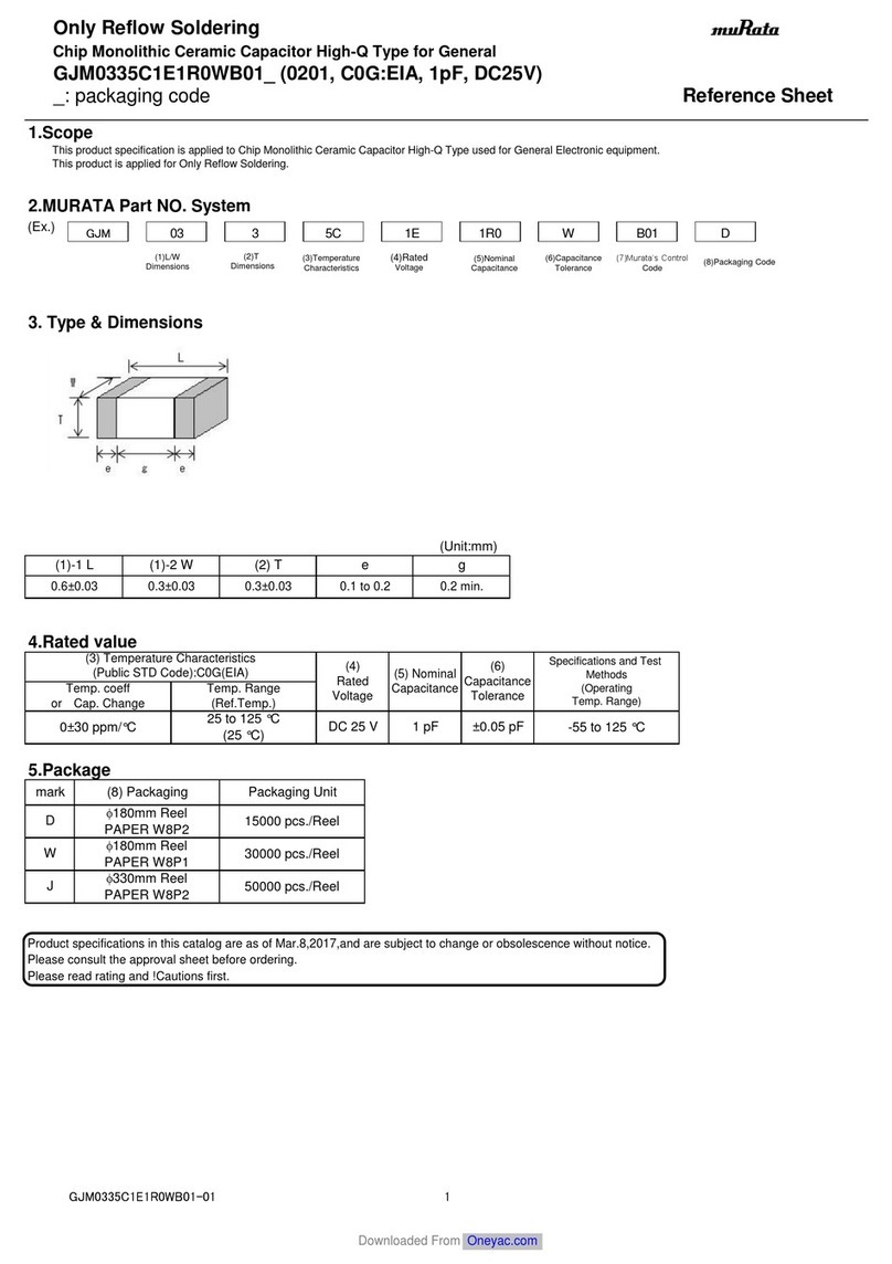
Murata
Murata GJM0335C1E1R0WB01 Series Reference sheet
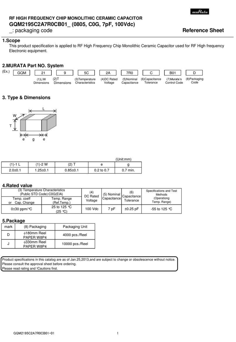
Murata
Murata GQM2195C2A7R0CB01 Series Reference sheet
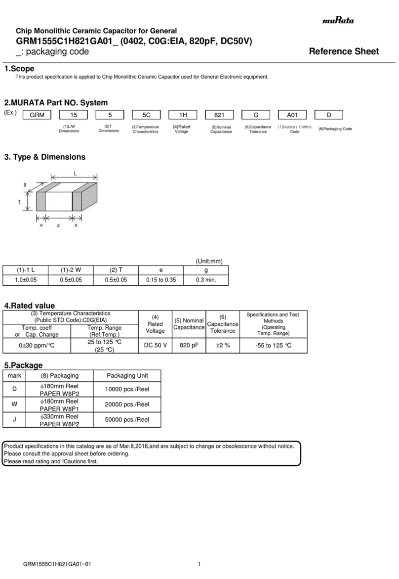
Murata
Murata GRM1555C1H821GA01 Series Reference sheet
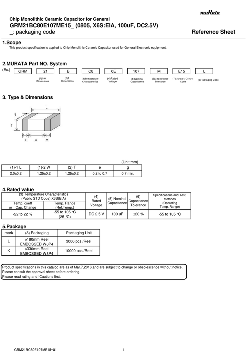
Murata
Murata GRM21BC80E107ME15 Series Reference sheet
Murata
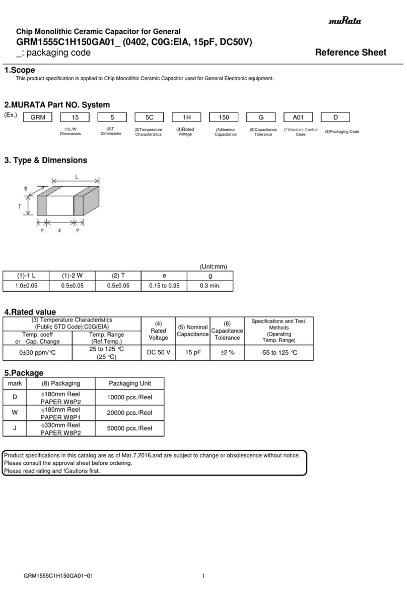
Murata GRM1555C1H150GA01 Series Reference sheet
