Charles 3653-36 User manual

Section 365–336–202
Equipment Issue 2
Second Printing, January 2001Telecommunications Group
2001Charles Industries Ltd.
CLEI is a trademark of Bell Communications Research, Inc.
All rights reserved. Printed in United States of America.
The availability of features and technical specifications herein subject to change without notice. Page 1 of 12
3653–36 4W Transmission Only with Extended Range and
Loopback (4W TO/ER/LB) Channel Unit
CONTENTS PAGE
Part 1. GENERAL 2. . . . . . . . . . . . . . . . . . . . . . . . . . . . . . . . . . . . . . . . . . . . . . . . . . . . . . . . . . . . . . . . . . . . . . . . . . . . .
Part 2. INSPECTION 2. . . . . . . . . . . . . . . . . . . . . . . . . . . . . . . . . . . . . . . . . . . . . . . . . . . . . . . . . . . . . . . . . . . . . . . . . . .
Part 3. APPLICATION GUIDELINES 3. . . . . . . . . . . . . . . . . . . . . . . . . . . . . . . . . . . . . . . . . . . . . . . . . . . . . . . . . . . . .
Part 4. CIRCUIT DESCRIPTION 3. . . . . . . . . . . . . . . . . . . . . . . . . . . . . . . . . . . . . . . . . . . . . . . . . . . . . . . . . . . . . . . . .
Part 5. MOUNTING 5. . . . . . . . . . . . . . . . . . . . . . . . . . . . . . . . . . . . . . . . . . . . . . . . . . . . . . . . . . . . . . . . . . . . . . . . . . . .
Part 6. INSTALLER CONNECTIONS 6. . . . . . . . . . . . . . . . . . . . . . . . . . . . . . . . . . . . . . . . . . . . . . . . . . . . . . . . . . . . .
Part 7. OPTIONS 6. . . . . . . . . . . . . . . . . . . . . . . . . . . . . . . . . . . . . . . . . . . . . . . . . . . . . . . . . . . . . . . . . . . . . . . . . . . . . .
Part 8. ALIGNMENT 8. . . . . . . . . . . . . . . . . . . . . . . . . . . . . . . . . . . . . . . . . . . . . . . . . . . . . . . . . . . . . . . . . . . . . . . . . . .
Part 9. TESTING 10. . . . . . . . . . . . . . . . . . . . . . . . . . . . . . . . . . . . . . . . . . . . . . . . . . . . . . . . . . . . . . . . . . . . . . . . . . . . .
Part 10. TECHNICAL ASSISTANCE 10. . . . . . . . . . . . . . . . . . . . . . . . . . . . . . . . . . . . . . . . . . . . . . . . . . . . . . . . . . . . .
Part 11. WARRANTY & CUSTOMER SERVICE 10. . . . . . . . . . . . . . . . . . . . . . . . . . . . . . . . . . . . . . . . . . . . . . . . . . .
Part 12. SPECIFICATIONS 11. . . . . . . . . . . . . . . . . . . . . . . . . . . . . . . . . . . . . . . . . . . . . . . . . . . . . . . . . . . . . . . . . . . . .
T
&
R
T1
&
R1
DROP
3653-36
MLB
LINE
DROP
LB
4W
TO/ER/LB
ISS 2
PUSH ON
PUSH OFF
LINE
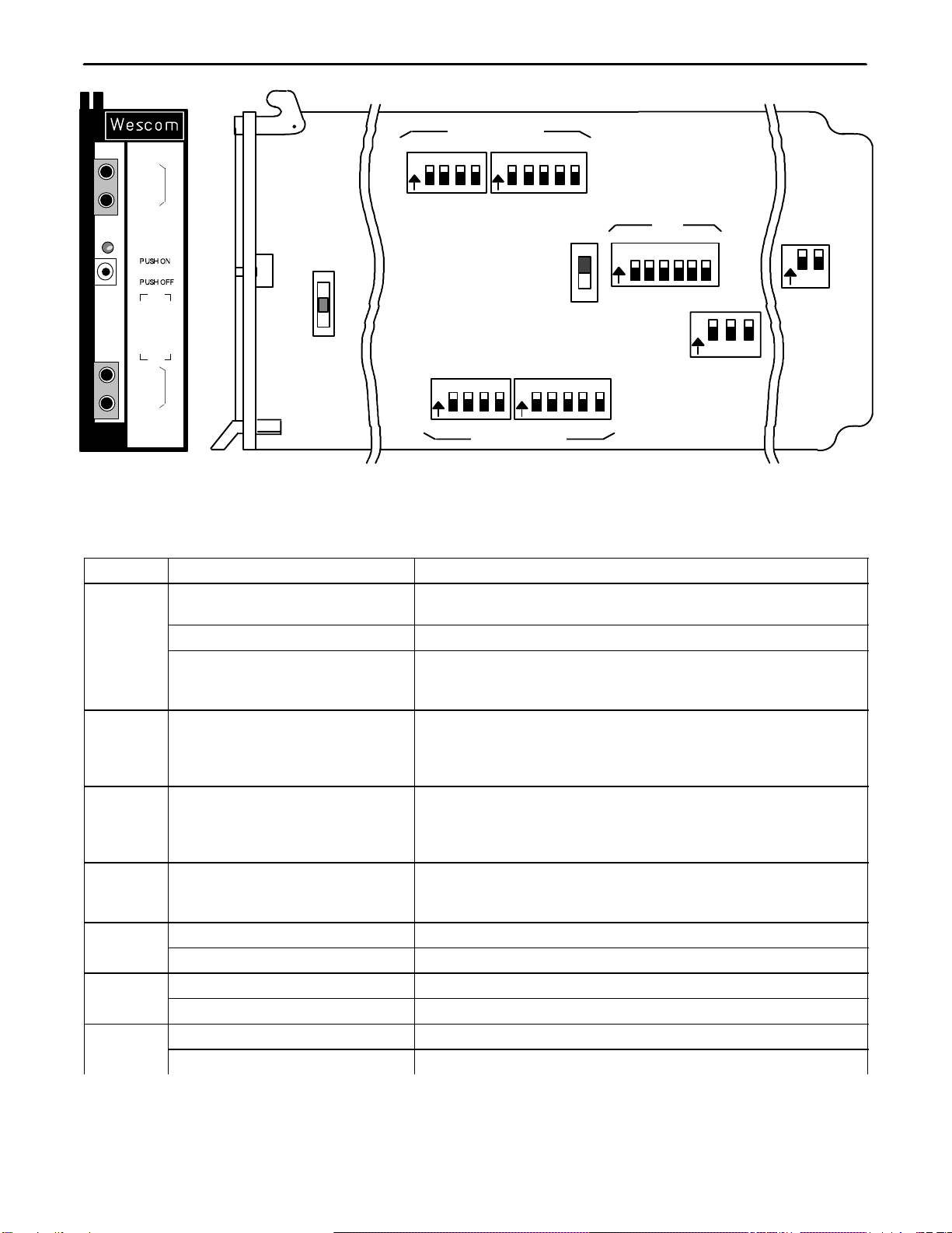
Figure 1. 3653–36 Front Panel

Section 365–336–202
2
1. GENERAL
1.1 Document Purpose
This practice provides general, application, circuit, optioning, installation and testing information for the Charles
Industries 3653–36 4-Wire Transmission Only with Extended Range and Loopback (4W TO/ER/LB) channel unit,
shown in Figure 1.
1.2 Document Status
This document is reprinted to include a general editorial update
1.3 Equipment Purpose/Description
The 3653–36 provides a direct interface between 600 ohm 4W VF or voiceband data (modem) circuits and the
360/363 D4 Digital Carrier Terminal common equipment.
1.4 Equipment Location/Mounting
The 3653–36 is mounted in a Wescom 360/363 D4 Channel Bank or Digital Carrier Terminal.
1.5 Equipment Features
The 3653–36 provides the following features:
Complies with AT&T Pub. 43801 Specifications
Accommodates transmit and receive TLP levels from –19.5 to +13dBm
Provides 600 ohms impedance at the 4W port interface
Provides 2713Hz tone-activated loopback
Provides selectable 4-min/20-min/none loopback automatic timeouts
Provides selectable tone loopback disable
Prescription adjustable loopback level of up to 31.5dB of gain/attenuation in 0.5dB increments
Front-panel manual loopback switch
Front-panel-mounted bantam jacks for accessing the transmit and receive ports
Front-panel LED indicating loopback status
Optional sealing current configuration with automatic ZAP
2. INSPECTION
2.1 Inspect for Damages
Inspect the equipment thoroughly upon delivery. If the equipment has been damaged in transit, immediately re-
port the extent of damage to the transportation company.
2.2 Equipment Identification
Charles Industries’ equipment is identified by a model and issue number imprinted on the front panel or located
elsewhere on the equipment. Each time a major engineering design change is made on the equipment, the issue
number is advanced by 1 and imprinted on subsequent units manufactured. Therefore, be sure to include both
the model number and its issue number when making inquiries about the equipment.
2.3 Static Concerns
Each module is shipped in static-protective packaging to prevent electrostatic charges from damaging static-sen-
sitive devices. Use approved static-preventive measures, such as static-conductive wrist straps and a static-dissi-

Section 365-336-202
3
pative mat, when handling modules outside of their protective packaging. A module intended for future use should
be tested as soon as possible and returned to its original protective packaging for storage.
This equipment contains staticsensitive electronic devices. To prevent electrostatic charges from
damaging staticsensitive units:
Use approved static preventive measures (such as a static-conductive wrist strap and a
static-dissipative mat) at all times whenever touching units outside of their original, shipped
static-protective packaging.
Do not ship or store units near strong electrostatic, electromagnetic, or magnetic fields.
Use static-protective packaging for shipping or storage.
STATIC-SENSITIVE
3. APPLICATION GUIDELINES
The 3653–36 provides an interface between 600-ohm balanced 4-wire (4W) VF/DATA circuits and the 360/363
D4 Digital Carrier Terminal common equipment. The receive and transmit paths of the 3653–36 provide level con-
trols to accommodate TLP levels from –19.5 to +13.0 dBm. The 3653–36 also provides tone or manually acti-
vated loopback function that can eliminate the need for external loopback equipment. A typical application is
shown in Figure 2.
360/363 D4
DIGITAL
CARRIER
TERMINAL T1/DS1
FACILITY 3653–36
4W TO/
ER/LB
T
R
T1
R1
D
A
T
A
4W TO/
ER/LB
3653–36
M
O
D
E
M
A
N
A-
L
O
G
360/363 D4
DIGITAL
CARRIER
TERMINAL
M
O
D
E
M
A
N
A
L
O
G
D
A
T
A
Figure 2. Typical 3653–36 4W TO/ER/LB Application
4. CIRCUIT DESCRIPTION
Refer to Figure 3, the 3653–36 block diagram, as needed while reading the following circuit description.
4.1 Transmit VF Path
VF signals applied to the input T&R (pins 50 and 48) are routed through the DROP and LINE lifting jacks to trans-
former T1. Transformer T1 provides a balanced input and DC isolation from the line.
Voice energy from transformer T1 is routed to the XMT level control circuit.
The XMT level control provides a total of 32.5 dB of level control in 0.1 dB increments. Switches S2 and S3 asso-
ciated with this circuit allow the transmit port to accommodate a –19.5 to +13.0 dBm input TLP range.
The adjusted VF signal is then applied to the XMT FILTER circuit. The filter suppresses frequencies that are out-
side of the standard voice frequency and prevents them from entering the ENCODER. The ENCODER performs
an analog-to-digital (A/D) conversion and sends the resulting PCM signal to the 360/363 common equipment via
the XDATA lead.
4.2 Receive VF Path
The PCM digital signal from the far end is received by the 360/363 common equipment, is routed to the 3653–36
via the RDATA lead, and is applied to the DECODER circuit. The DECODER then performs a digital-to-analog
(D/A) conversion of the signal. The analog signal from the DECODER circuit is applied to the RCV FILTER. The
RCV FILTER suppresses frequencies that are outside the bandwidth of the standard voice band.
The output of the RCV filter is applied to the RCV level control. The RCV level control provides a total of 32.5 dB
of level control in 0.1 dB increments. Switches S4 and S5 allow the receive port to accommodate a –19.5 to
+13.0 dBm input TLP range.

Section 365–336–202
4
The adjusted VF signal is then routed through transformer T2 which provides dc isolation from the line and a bal-
anced output level. The signal is then fed to the T1 & R1 leads (pins 8 and 7) via the LINE and DROP jacks.
4.3 Sealing Current
Three different configurations of Sealing Current are provided and are selected by option Switch S1.
The SX (Simplex) position supplies ground to leads T and R and –48Vdc, through a 750-ohm thermistor, to leads
T1 and R1. When the module is first plugged in, the current surges to approximately 100mA and decreases
quickly to a steady simplex current of approximately 30mA. This low value of dc current being applied to the 4W
cable pairs, on a simplex basis, will break down any resistance film which may build up at nonsoldered splices.
Continued application of this dc sealing current sustains the normal resistance of the cable pairs and prevents
degradation of transmission performance.
In the LP (Loop) position, the simplex leads of T1 and T2 are shorted together. Sealing current from the analog
facility will be looped by the channel unit.
The OPN (Open) position is used when no sealing current is required.
XDATA
4W OUTPUT
RANGE +13
TO
-19.5dBm
R 48
T 50
R1 7
T1 8
T-SIG
S11-1
S1-A
LP
SX
OPN
OPN
LP
S1-B
SX
4W INPUT
RANGE
-19.5 TO
+13dBm
PC board connector pin
NOTES:
XXXX
SEALING
CURRENT
GENERATOR
T1
T2
RELAY
LB LOOPBACK
1.
2.
3.
4.
MLB
LB
LINE
DROP
T1&R1
LINE
DROP
T&R
-48V
XMT LEVEL
CONTROL
S2 & S3
FILTER ENCODER
LB
LOOPBACK
LEVEL
CONTROL
S6
S7
&
LB
RCV LEVEL
CONTROL
S4 & S5
FILTER DECODER RDATA
R-SIG
S11-2
DIS
TO
4
20
DIS
LB
S8-1
S8-2
S8-3
TONE
DETECTOR
CIRCUIT
5. Ganged switches are indicated by alphabeti
cally suffixed reference. Numerical suffix de
notes discrete switch within a package.
N. O., N. C. Relay contact
Frontpanel marking
Signal flow direction
Figure 3. 3653–36 Block Diagram

Section 365-336-202
5
4.4 2713Hz Tone-Activated Loopback
The 3653–36 provides tone-operated loopback toward the digital facility. A continuous 2713Hz loopback control
signal applied from the far end for a minimum of 2.2 seconds and then removed will result in the operation and
latching of the LB RELAY and the illumination of the front-panel LB LED. While operated, the LB RELAY will per-
form the following functions:
Opens the 4W port to the 4W equipment preventing transmission.
Loops all voice-band signals from the RCV output to the XMT path, enabling all active components to
be verified.
The EQUAL LEVEL LOOPBACK circuit provides prescription level adjustment of +31.5dB in 0.5dB steps to
match the RCV output to the XMT path input.
Loopback release is accomplished by the reapplication of 2713Hz tone (for a minimum of 1.1 seconds) to the
3653–36. After the 2713Hz tone has been received, the LB RELAY releases and the LB LED extinguishes, end-
ing the loopback condition.
The loopback control circuit provides several control options as selected by switch S8. The tone activated loop-
back feature can be disabled or enabled. In addition, when the unit has been looped via a 2713 Hz tone, the cir-
cuit can be optioned to have a 4-min, 20-min, automatic release, or no timeout.
4.5 Manual Loopback
The 3653–36 can be manually placed in the loopback mode by momentarily operating the front-panel MLB push-
button switch (S9). The module will remain in the manual loopback mode regardless of the settings of S8. To re-
lease the manual loopback mode, the MLB switch is again momentarily operated.
4.6 7 5/6-Bit or 8-Bit (Encoding & Decoding)
The 3653–36 provides 7 5/6-bit or 8-bit encoding and decoding schemes for the transmit and receive paths to/
from the facility. The 7 5/6-bit encoding/decoding scheme provides for end-to-end compatibility with E&M chan-
nel units. In this scheme a constant off-hook (logic 1) is transmitted on the A+B signaling bits to the far end.
The full 8-bit encoding/decoding scheme provides a greater signal-to-noise ratio than the 7 5/6-bit scheme and
does not transmit an off-hook signal to the far end.
5. MOUNTING
The 3653–36 mounts in one channel unit slot of a 360/363 D4 terminal. The 3653–36 is equipped with an insert/
eject lever in the form of a hinged front panel which ensures a positive connection of the channel unit’s card-edge
connector to the backplane connector when the unit is installed. The insert/eject lever also facilitates removal of
the unit.
Installation and removal of modules should be done with care. Do not force a module into place. If
excessive resistance is encountered while installing a module, remove the module and check the
card guides and connector to verify proper alignment and the absence of foreign material.
CAUTION
Step Action
1. Align the channel unit with the appropriate card-guided slot of the terminal.
2. Slide the unit into the slot with the hinged front panel in a horizontal (up) position.
3. When the top portion of the hinged front panel is under the front lip of the terminal, push down on the
front panel until it is in the vertical position. The channel unit’s card-edge connector will begin to make
contact with the inner portion of the backplane connector.
4. Continue applying light pressure onto the bottom edge of the front panel until the unit snaps into place.

Section 365–336–202
6
6. INSTALLER CONNECTIONS
Installer connections are made to the channel unit via connectorized cable connectors that are part of the chan-
nel bank assembly. Refer to the appropriate channel bank installer practice for pin assignments.
7. OPTIONS
The 3653–36 is equipped with push button, DIP, and slide switch options that are used to condition the module
for proper application and operation. Refer to Figure 4 and Table 1 for the location of these options while reading
the following instructions.
7.1 Slide-Switch S1 – Sealing Current Control
When S1 is placed in the SX (Simplex) position the 3653–36 provides sealing current to the 4W facility. In the SX
position the module also provides an automatic ZAP when it is first plugged in. When switch S1 is placed in the
LP (Loop) position, the simplex leads of T1 and T2 are shorted together, which allows the channel unit to loop
sealing current applied from the other end of the analog facility. The OPN (Open) position is used when no seal-
ing current source or sink is required.
7.2 Switches S2 and S3 – XMT ATTN (Transmit Prescription Attenuation)
Switches S2 and S3 form a 9-section DIP switch that provides up to 32.5dB of attenuation, in 0.1dB steps, to ac-
commodate various input TLPs. Refer to Transmit Alignment in Part 8.
7.3 Switches S4 and S5 – RCV ATTN (Receive Prescription Attenuation)
Switches S4 and S5 form a 9-section DIP switch that provides up to 32.5dB of attenuation, in 0.1dB steps, to ac-
commodate various output TLPs. Refer to Receive Alignment in Part 8.
7.4 Switches S6 and S7 – ELL GAIN/ATTN (Equal Level Loopback Prescription Gain/Attenuation)
Switch S6 is a 6-section DIP switch that provides up to 31.5dB of equal level loopback in 0.5dB steps. S7 is a
two-position slide switch to set equal level loopback for gain or attenuation. Refer to Equal Level Loopback Align-
ment in Part 8.
7.5 Switch S8 – Loopback Controls
S8 is a 3-position DIP switch that controls the loopback features of the unit. To disable the tone-activated loop-
back feature completely, set S8–3 to DIS; to enable the tone-activated loopback feature, set S8–3 to LB. To allow
for a 4-minute automatic loopback timeout, set S8–2 to 4; to allow for a 20-minute timeout, set S8–2 to 20. To
allow for no (infinite) loopback release timeout, set S8–1 to DIS; to allow for a 4 or 20-minute automatic timeout,
set S8–1 to TO.
7.6 Switch S9 – MLB (Manual Loopback)
The MLB front-panel switch (S9) is a ‘push-on/push-off’ push-button switch. With each actuation of the MLB
switch, the channel unit will alternate between loopback and the normal operating mode. When placed into loop-
back via the manual switch, the channel unit will remain in the loopback state, regardless of the optioning of S8
loopback controls.
7.7 Switch S11 – T-SIG, R-SIG (7 5/6-Bit or 8-Bit Encoding and Decoding)
S11 is a 2-section DIP switch. Place switch S11–1 (T-SIG) and S11–2 (R-SIG) to the ON position for a 7 5/6-bit
encoding/decoding scheme for end-to-end compatibility with E&M channel units. In this scheme an off-hook (logic
1) is transmitted on the A&B signaling bits to the far end. Place switch S11–1 (T-SIG) and S11–2 (R-SIG) to the
OFF position for a full 8-bit encoding/decoding scheme which provides a greater signal-to-noise ratio than the 7
5/6-bit scheme and does not transmit an off-hook to the far end.
Section 365-336-202
7
T
S
I
G
R
S
I
G
O
N
123456
O
N
12
S3
.1 .2 .4 .8
O
N
1234
S2
1248
O
N
1234
16
5
S6
S4
.1 .2 .4 .8
O
N
1234
S5
1248
O
N
1234
16
5
S8
MLB
S9 SX
OPN
LP
S1 O
N
12
S11
3
TO 20 LB
DIS 4 DIS
XMT ATTN (DB)
ELL
RCV ATTN (dB)
.5 1 2 4 8 16
T
&
R
T1
&
R1
DROP
3653-36
MLB
LINE
DROP
LINE
LB
4W
TO/ER/LB
ISS 2
GAIN
ATTN
S7
Figure 4. 3653–36 Option Locations
Table 1. Description of Figure 4
Option Position Use to
S1 SX (Simplex) Sealing current is generated by the channel unit with automatic
ZAP when the module is first plugged in.
OPN (Open) No sealing current.
LP(Loop) Loop sealing current supplied from the other end of the analog
facility by the channel unit via the simplex leads of transformers
T1 and T2.
S2, S3 ON/OFF as required. Refer to
Transmit Alignment in Part 8 Switches S2 and S3 form a 9-section DIP switch that provides
up to 32.5dB of attenuation, in 0.1dB steps, for adjusting the
transmit path to the proper operating level at the ENCODER
input.
S4, S5 ON/OFF as required. Refer to
Receive Alignment in Part 8 Switches S4 and S5 form a 9-section DIP switch that provides
up to 32.5dB of attenuation, in 0.1dB steps, for adjusting the
receive path to the proper operating level output at leads T1 &
R1.
S6, S7 ON/OFF as required. Refer to
Equal Level Loopback Alignment
in Part 8
Switch S6 is a 6-section DIP switch that provides up to 31.5dB
of equal level loopback in 0.5dB steps. S7 is a 2-position slide
switch that selects loopback path gain or attenuation.
S8–1 TO (ON) For automatic loopback timeout.
DIS (OFF) For no loopback timeout.
S8–2 20 (ON) For 20-minute loopback timeout.
4 (OFF) For 4-minute loopback timeout.
S8–3 LB (ON) For tone-activated loopback enable.
DIS (OFF) To disable tone-activated loopback.

Section 365–336–202
8
Option Use toPosition
S9 (MLB)
front-pan-
el push-
With each operation of switch S9,
the channel unit alternates be-
tween manual loopback and nor-
To manually activate Loopback (MLB).
el
ush
button
tween
manual
loo back
and
nor
mal operating mode. Manual
loopback mode overrides the op-
tioning of S8.
To manually release Loopback (MLB).
S10 –––––––– Not used
S11–1
(T SIG)
OFF For 8-bit encoding.
(T–SIG) ON For 7 5/6 encoding. (Normal mode)
S11–2
(R SIG)
OFF For 8-bit decoding.
(R–SIG) ON For 7 5/6 decoding. (Normal mode)
8. ALIGNMENT
8.1 Transmit Alignment
The XMT ATTN switches S2 and S3 are prescription controls that provide attenuation from 0.0 to 32.5dB in incre-
ments of 0.1dB to accommodate an input TLP range from –19.5 to 13.0dBm. To adjust the transmit path to the
proper operating level, the difference between –19.5 and the transmit TLP at T&R must be obtained:
XMT ATTN = TLP – (–19.5)
Use Table 2 for common TLP values.
For example, for a 0 db transmit TLP, set the sum of S2 and S3 to 19.5 by placing the switch sections shown be-
low in the ON position.
248161.2.4.8.1
O
N
S2
O
N
S3 ON
16 + 2 + 1 + 0.4 + 0.1 = 19.5
XMT ATTN (DB)
8.2 Receive Alignment
The RCV ATTN switches S4 and S5 are prescription controls that provide attenuation from 0.0 to 32.5dB in incre-
ments of 0.1dB to accommodate an output TLP range from +13.0 to –19.5dBm. To adjust the receive path to the
proper operating level, the difference between +13.0 and the receive TLP at T1 & R1 must be obtained:
RCV ATTN = 13.0 – TLP
Use Table 3 for common TLP values.
For example, for a 0 db receive TLP, set the sum of S4 and S5 to 13 by placing the switch sections shown below
in the ON position.
248161.2.4 .8.1
O
NS4
O
N
S5 ON
8 + 4 + 1 = 13
RCV ATTN (DB)
8.3 Equal Level Loopback (ELL) Alignment
The ELL switches S6 and S7 are prescription controls that provide adjustment to match the RCV path output to
the XMT path input. Perform the ELL alignment as follows:

Section 365-336-202
9
Step Action
1. Determine the required ELL by adding the setting for the XMT ATTN and RCV ATTN settings and sub-
tracting 32.5.
ELL = XMT ATTN + RCV ATTN – 32.5
2. Set switch S6 to the required ELL to the nearest 0.5dB.
3. If the ELL is a negative number, set switch S7 to ATTN position; if the ELL is a positive number, set
switch S7 to the GAIN position.
Table 2. Common Transmit TLP Values
Desired TLP Set S3 & S2 Desired TLP Set S3 & S2
+13
+12
+11
+10
+9
+8
+7
+6
+5
+4
+3
+2
+1
+0.5
0
–0.5
–1
–2
32.5
31.5
30.5
29.5
28.5
27.5
26.5
25.5
24.5
23.5
22.5
21.5
20.5
20
19.5
19
18.5
17.5
–3
–4
–5
–6
–7
–8
–9
–10
–11
–12
–13
–14
–15
–16
–17
–18
–19.5
16.5
15.5
14.5
13.5
12.5
11.5
10.5
9.5
8.5
7.5
6.5
5.5
4.5
3.5
2.5
1.5
0
Table 3. Common Transmit TLP Values
Desired TLP Set S4 & S5 Desired TLP Set S4 & S5
+13
+12
+11
+10
+9
+8
+7
+6
+5
+4
+3
+2
+1
+0.5
0
–0.5
–1
–2
0
1
2
3
4
5
6
7
8
9
10
11
12
12.5
13
13.5
14
15
–3
–4
–5
–6
–7
–8
–9
–10
–11
–12
–13
–14
–15
–16
–17
–18
–19.5
16
17
18
19
20
21
22
23
24
25
26
27
28
29
30
31
32.5

Section 365–336–202
10
9. TESTING
After completing Parts 4 through 8, perform end-to-end transmission test per local practice to verify proper opera-
tion. If trouble is encountered, recheck all installer connections, options and alignment settings, and verify that the
channel unit is making positive connection to the backplane connector. If trouble persists, replace the unit with a
similar unit known to be in proper operating order and retest the facility.
10. TECHNICAL ASSISTANCE
If technical assistance is required, contact Charles Industries’ Technical Services Center at:
847–806–8500
847–806–8556 (FAX)
800–607–8500
[email protected] (e-mail)
11. WARRANTY & CUSTOMER SERVICE
11.1 Warranty
Charles Industries, Ltd. offers an industry-leading, 5-year warranty on products manufactured by Charles Indus-
tries. Contact your local Sales Representative at the address or telephone numbers below for warranty details.
The warranty provisions are subject to change without notice. The terms and conditions applicable to any specific
sale of product shall be defined in the resulting sales contract.
Charles Industries, Ltd.
5600 Apollo Drive
Rolling Meadows, Illinois 60008–4049
847–806–6300 (Main Office)
847–806–6231 (FAX)
11.2 Field Repairs (In-Warranty Units)
Field repairs involving the replacement of components within a unit are not recommended and may void the war-
ranty and compatibility with any applicable regulatory or agency requirements. If a unit needs repair, contact
Charles Industries, Ltd. for replacement or repair instructions, or follow the
Repair Service Procedure
below.
11.3 Advanced Replacement Service (In-Warranty Units)
Charles Industries, Ltd. offers an “advanced replacement” service if a replacement unit is required as soon as
possible. With this service, the unit will be shipped in the fastest manner consistent with the urgency of the situa-
tion. In most cases, there are no charges for in-warranty repairs, except for the transportation charges of the unit
and for a testing and handling charge for units returned with no trouble found. Upon receipt of the advanced re-
placement unit, return the out-of-service unit in the carton in which the replacement was shipped, using the pre-
addressed shipping label provided. Call your customer service representative at the telephone number above for
more details.
11.4 Standard Repair and Replacement Service (Both In-Warranty and Out-Of-Warranty Units)
Charles Industries, Ltd. offers a standard repair or exchange service for units either in- or out-of-warranty. With
this service, units may be shipped to Charles Industries for either repair and quality testing or exchanged for a
replacement unit, as determined by Charles Industries. Follow the
Repair Service Procedure
below to return units
and to secure a repair or replacement. A handling charge applies for equipment returned with no trouble found. To
obtain more details of this service and a schedule of prices, contact the CI Service Center at 217–932–5288 (FAX
217–932–2943).
Repair Service Procedure
1. Prepare, complete, and enclose a purchase order in the box with the equipment to be returned.
2. Include the following information:

Section 365-336-202
11
– Company name and address
– Contact name and phone number
– Inventory of equipment being shipped
– Particulars as to the nature of the failure
– Return shipping address
3. Ship the equipment, purchase order, and above-listed information, transportation prepaid, to the ser-
vice center address shown below.
CI Service Center
503 N.E. 15th St., P.O. Box 339
Casey, IL 62420–2054
4. Most repaired or replaced units will be returned within 30 or 45 days, depending on the product type
and availability of repair parts. Repaired units are warranted for either 90 days from the date of repair
or for the remaining unexpired portion of the original warranty, whichever is longer.
12. SPECIFICATIONS
12.1 Agency Compliance
(a) Recognized under Underwriters Laboratories Standard 1459, Second Edition. Compliance is re-
stricted to inside plant wiring. Field repairs may void compliance.
(b) FCC P.15 Class A.
(c) Meets Canadian CSA and DOC requirements.
12.2 Electrical Specifications
12.2.1. Power
(a) POWER REQUIREMENTS: Power is supplied via the 3609–XX PSU which is part of the 360/363
Channel Bank common equipment.
12.2.2. Transmission
(b) 4W XMT INPUT TLP RANGE: +13.0 to –19.5dB.
(c) 4W RCV OUTPUT TLP RANGE: +13.0 to –19.5dB.
(d) TRANSMIT AND RECEIVE PRESCRIPTION ATTENUATION: 0.0 to 32.5dB in 0.1dB steps.
(e) LONGITUDINAL BALANCE (REFERENCED TO –16dBM TLP): 74dB minimum at 200Hz to 1KHz;
69dB minimum at 3kHz.
(f) SIGNAL TO DISTORTION RATIO: 35dB minimum at zero to –30dBm0; 29dB minimum at –40dBm0;
25dB minimum at –45dBm0.
(g) RETURN LOSS: 23dB minimum at 300Hz to 3KHz; 28dB minimum at 1kHz.
(h) TRANSMIT/RECEIVE IDLE CHANNEL NOISE: 20dBrnC0 maximum.
(i) TRANSMIT AND RECEIVE PATH FREQUENCY RESPONSE: (Referenced at 1kHz)

Section 365–336–202
12
Table 4. Frequency Response
FREQ (Hz) XMT (dB) RCV (dB)
60 Less than –14.0 ––––––––
200 +0.15 to –2.0 +0.15 to –1.0
300 +0.15 to –0.15 +0.15 to –0.15
1000 0 (REF) 0 (REF)
3000 +0.15 to –0.15 +0.15 to –0.15
3400 0 to –1.5 0 to –1.5
4000 Less than –14.0 Less than –14.0
(j) CROSSTALK: 61dBm0 minimum at 400Hz; 71dBm0 minimum at 700Hz to 1KHz; 70dBm0 minimum
at 3kHz.
(k) LEVEL TRACKING SINGLE-ENDED AT 1020Hz: +0.25dB from +3 to –37dBm0, +0.5dB from –38 to
–50dBm0.
12.2.3. Loopback
(l) DETECTOR FREQUENCY: Will detect within 2713 + 7Hz; will not detect outside of 2713 + 35Hz.
(m) DETECTOR AMPLITUDE: Will detect 0.0 to –30dBm0; will not detect less than –40dBm0.
(n) DETECTOR TIMING: Activate, 2.2 seconds; deactivate, 1.1 seconds.
(o) ELL GAIN/ATTENUATION RANGE: 0.0 to 31.5dB in 0.5dB increments.
12.3 Physical Specifications
The physical characteristics of the 3653–36 4W are shown in Table 5.
Table 5. Physical Specifications
Feature U.S. Metric
Height 4.25 inches 10.8 centimeters
Width 1.31 inches 3.3 centimeters
Depth 10.31 inches 26.2 centimeters
Weight 9.25 ounces 263 grams
Temperature 32 to 122F 0 to 50C
Humidity To 95% (no condensation)
Table of contents
Other Charles Industrial Electrical manuals


Popular Industrial Electrical manuals by other brands


ABB
ABB Smart Communication Card manual

Cooper Power Systems
Cooper Power Systems RVE Maintenance instructions

Murata
Murata GRM1555C1H1R0BA01 Series Reference sheet

Murata
Murata GJM0335C1E1R3BB01 Series Reference sheet

Fritsch
Fritsch 16.60 0 Series operating instructions

Murata
Murata GRM1885C1H180JA01 Series Reference sheet

ABB
ABB ACS 800 Series Cabinet installation and operating instruction

Murata
Murata GRM1885C1H152JA01 Series Reference sheet

Eaton
Eaton C30C-P Series Instruction leaflet

Murata
Murata GRJ188R72A104KE11 Series Reference sheet

Siemens
Siemens MICROMASTER 440 Maintenance Instruction

Murata
Murata GRM0335C1H150FA01 Series Reference sheet