Charles 3653-61 User manual
Section 365–361–206
Equipment Issue 6
First Printing, September 2003Telecommunications Group
2003Charles Industries Ltd.
All rights reserved. Printed in United States of America.
The availability of features and technical specifications herein subject to change without notice. Page 1 of 11
3653–61 4-Wire Transmission Only with Extended Range
(4W TO W/ER) Channel Unit
CONTENTS PAGE
Part 1. GENERAL 2. . . . . . . . . . . . . . . . . . . . . . . . . . . . . . . . . . . . . . . . . . . . . . . . . . . . . . . . . . . . . . . . . . . . . . . . . . . . .
Part 2. INSPECTION 2. . . . . . . . . . . . . . . . . . . . . . . . . . . . . . . . . . . . . . . . . . . . . . . . . . . . . . . . . . . . . . . . . . . . . . . . . . .
Part 3. APPLICATION GUIDELINES 3. . . . . . . . . . . . . . . . . . . . . . . . . . . . . . . . . . . . . . . . . . . . . . . . . . . . . . . . . . . . .
Part 4. CIRCUIT DESCRIPTION 5. . . . . . . . . . . . . . . . . . . . . . . . . . . . . . . . . . . . . . . . . . . . . . . . . . . . . . . . . . . . . . . . .
Part 5. MOUNTING 6. . . . . . . . . . . . . . . . . . . . . . . . . . . . . . . . . . . . . . . . . . . . . . . . . . . . . . . . . . . . . . . . . . . . . . . . . . . .
Part 6. INSTALLER CONNECTIONS 6. . . . . . . . . . . . . . . . . . . . . . . . . . . . . . . . . . . . . . . . . . . . . . . . . . . . . . . . . . . . .
Part 7. OPTIONS 6. . . . . . . . . . . . . . . . . . . . . . . . . . . . . . . . . . . . . . . . . . . . . . . . . . . . . . . . . . . . . . . . . . . . . . . . . . . . . .
Part 8. ALIGNMENT 8. . . . . . . . . . . . . . . . . . . . . . . . . . . . . . . . . . . . . . . . . . . . . . . . . . . . . . . . . . . . . . . . . . . . . . . . . . .
Part 9. TESTING 8. . . . . . . . . . . . . . . . . . . . . . . . . . . . . . . . . . . . . . . . . . . . . . . . . . . . . . . . . . . . . . . . . . . . . . . . . . . . . .
Part 10. TECHNICAL ASSISTANCE 8. . . . . . . . . . . . . . . . . . . . . . . . . . . . . . . . . . . . . . . . . . . . . . . . . . . . . . . . . . . . . .
Part 11. WARRANTY & CUSTOMER SERVICE 8. . . . . . . . . . . . . . . . . . . . . . . . . . . . . . . . . . . . . . . . . . . . . . . . . . . .
Part 12. SPECIFICATIONS 9. . . . . . . . . . . . . . . . . . . . . . . . . . . . . . . . . . . . . . . . . . . . . . . . . . . . . . . . . . . . . . . . . . . . . .
3653–61
LINE
DROP
T
&
R
T1
&
R1
LINE
DROP
4W TO
W/ER
ISS. 6
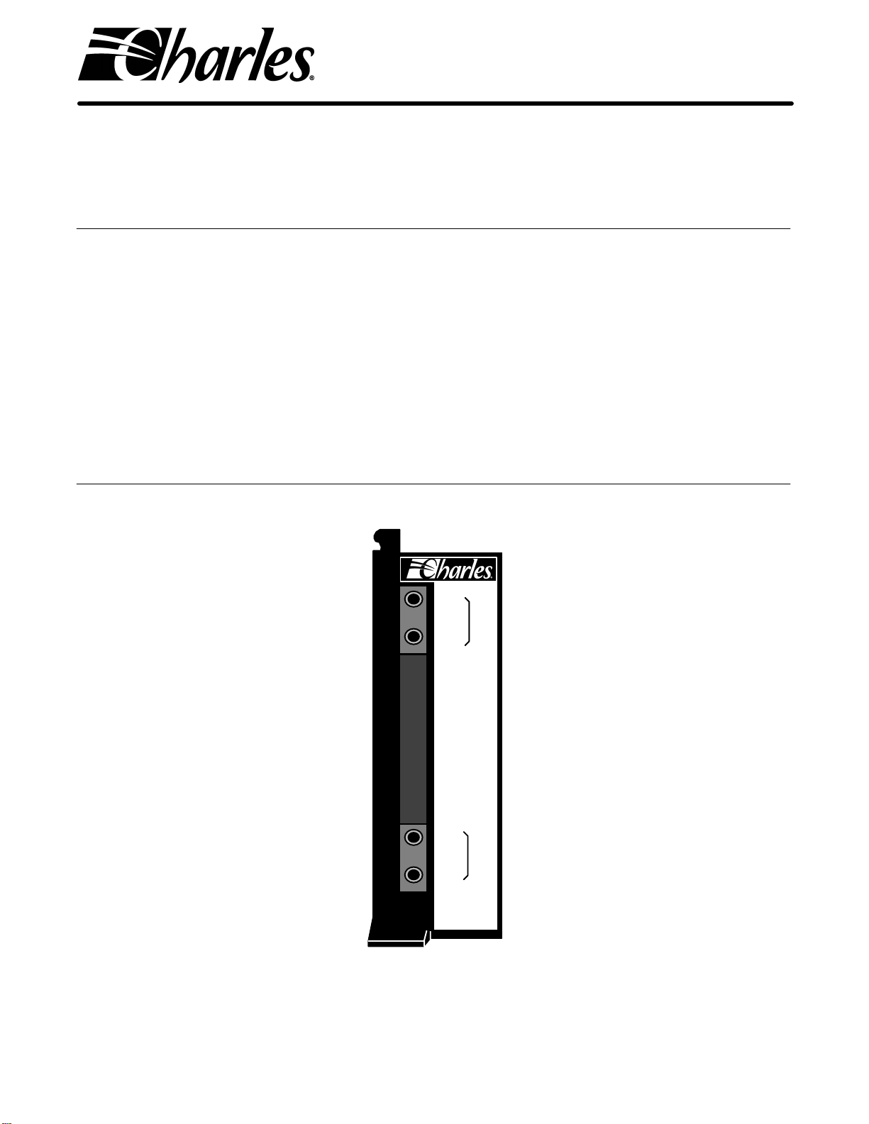
Figure 1. 3653–61 (Issue 6) 4W Transmission Only with Extended Range (4W TO W/ER) Channel Unit

Section 365–361–206
2
1. GENERAL
1.1 Document Purpose
This document provides information on the Charles Industries 3653–61 (Issue 6) 4-Wire Transmission Only with
Extended Range (4W TO W/ER) Channel Unit.
1.2 Equipment Function
The 3653–61, shown in Figure 1, is used in the Charles Industries 360/363 D4 Digital Carrier Terminal and pro-
vides a 600-ohm balanced interface to the 4-wire private line on the office-side of the facility.
Table 1. Channel Units (CUs) Replaced by 3653–61 (Issue 6)
CUs Replaced Description
3653–00 (Iss. 1) 4W TO
3653–01 (Iss. 1) 4W TO w/LC (Lead Conditioning)
3653–10 (Iss. 1) 4W TO
3653–60 (Iss. 1) 4W TO w/jacks
3653–61 (Iss. 1) 4W TO w/jacks and LC
3653–61 (Iss. 5) 4W TO w/jacks and ER
1.3 Equipment Location/Mounting
The 3653–61 occupies one channel unit slot of a Charles Industries 360/363 D4 Digital Carrier Terminal.
1.4 Equipment Features
The 3653–61 (Issue 6) 4W TO W/ER includes the following features:
Complies with AT&T Publication 43801 Specifications
Extended Range (ER) capability (+10 to –22.5dBm)
Prescription gain control of up to 32.5dB in 0.1dB increments in both the transmit and receive paths
Front-panel-accessible breaking jacks
Lead conditioning (trunk processing relay controls leads 1 and 2) during carrier failure
The breaking jacks provided on the T&R and T1&R1 leads of the 3653–61 provide access by breaking the line
toward the DROP (private line facility) and LINE (carrier facility).
2. INSPECTION
2.1 Inspect for Damages
Inspect the equipment thoroughly upon delivery. If the equipment has been damaged in transit, immediately re-
port the extent of damage to the transportation company.
2.2 Equipment Identification
Charles Industries’ equipment is identified by a model and issue number imprinted on the front panel or located
elsewhere on the equipment. Each time a major engineering design change is made on the equipment, the issue
number is advanced by 1 and imprinted on subsequent units manufactured. Therefore, be sure to include both
the model number and its issue number when making inquiries about the equipment.
2.3 Static Concerns
Each module is shipped in static-protective packaging to prevent electrostatic charges from damaging static-sen-
sitive devices. Use approved static-preventive measures, such as wrist straps, when handling modules outside of
Section 365-361-206
3
their protective packaging. A module intended for future use should be tested as soon as possible and returned to
its original protective packaging for storage.
Do not ship or store modules near strong electrostatic, electromagnetic, or magnetic fields, or in a
highly radioactive environment. Use the original static-protective packaging for shipping or storage.
CAUTION
3. APPLICATION GUIDELINES
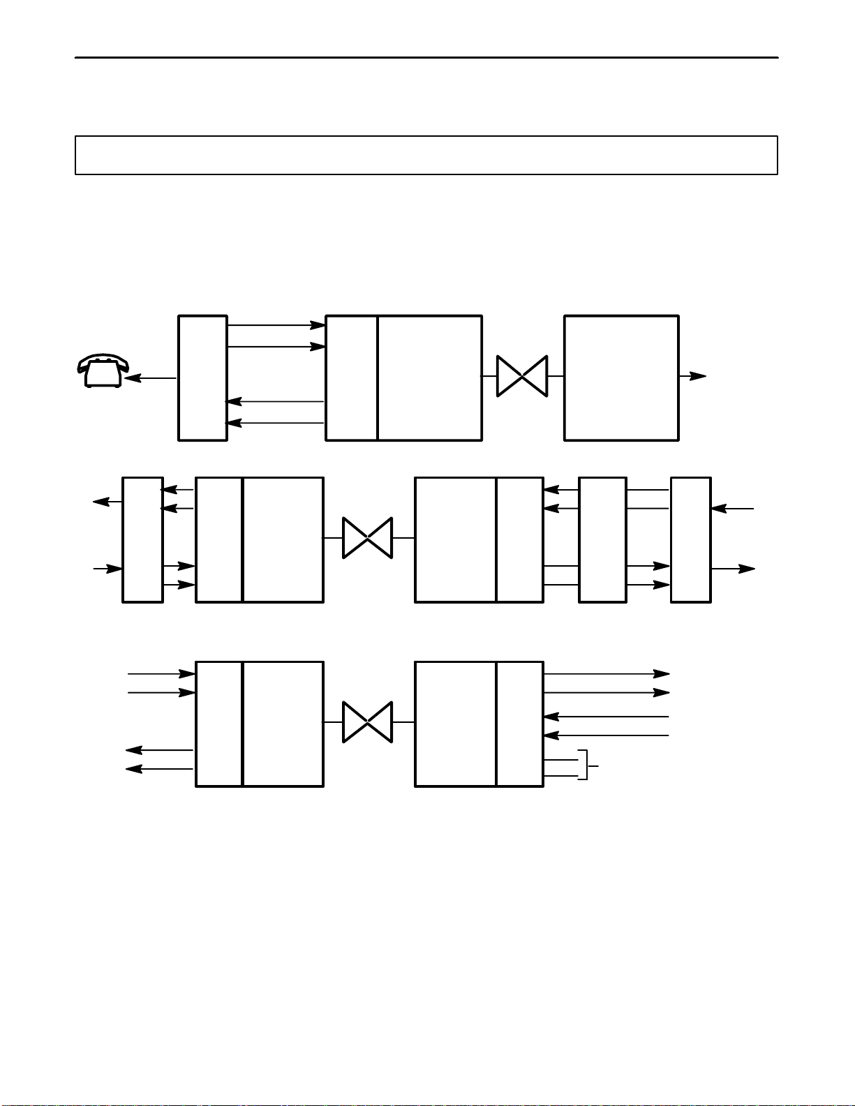
The 3653–61 provides a 600-ohm balanced interface between the 4-wire private line on the office side and the
360/363 D4 terminal. TO channel units are generally used in data or other applications that do not require signal-
ing. The ER feature allows signals to be transmitted and received to accommodate a range of Transmission Level
Points (TLPs) between +10 to –22.5dBm. Refer to Figure 2, Figure 3, and Figure 4 for typical applications.
SF
FXS
TĆCARRIER
FACILITY
360/363
D4
TERMINAL
MULTIPLEXER
(L TO T)
LĆCARRIER
FACILITY
(FDM)
4W SF
(INBAND FAĆ
CILITY)
T
R
T1
R1
4W
TO
W/ER
3653 61
Figure 2. 3653–61 Tandem Application
FSK
4W
TO
W/ER
360/363 D4
TERMINAL
T1
SPAN
LINE
3653 61
D
A
T
A
D
A
T
A
M
O
D
E
M
4W
TO
W/ER
3653 61
*4W
ADE
M
O
D
E
M
FSK
T
R
T1
R1
*4W AMPLITUDE DELAY EQUALIZER
360/363 D4
TERMINAL
Figure 3. 3653–61 Data Application
4W
TO
W/ER
360/363
D4
TERMINAL
T1
SPAN
LINE
3653 61
360/363
D4
TERMINAL
4W
E&M
3652 XX
T
R
T1
R1
T
R
T1
R1 E
M( NO CONNECTION)
Figure 4. 3653–61 TO 4W E&M Application
Section 365–361–206
4
6. FactoryĆinstalled optional strap
Alternate position
T&R
T1
XMT GAIN
4.8dB
XMT
PRESCRIPTION
GAIN (dB)
0 TO 32.5dB IN
.1dB STEPS
LINE
DROP
J1 A
J1 B
XMT
FILTER ENCODER XDATA
XC
(NOTE 18)
(XMT TLP:
+5.2dBm)
INPUT
RANGE +10
TO
22.5dBm
T 50
R 48
T1&R1
T2
RCV GAIN
+27.7dB
RCV
PRESCRIPTION
GAIN (dB)
0 TO 32.5dB IN
.1dB STEPS
LINE
DROP
J2 A
J2 B
RCV
FILTER DECODER RDATA
(RCV TLP:
+5.2dBm)
YC
(NOTE 18)
OUTPUT
RANGE +10
TO
22.5dBm
T1 8
R1 7
(NOTE 13)
S4 & S5
(NOTE 15)
S4 & S5
Y
TP
1 2
2 6 (NOTE 17)
48VS
48VR
48VS
48VS CGAW
TP
RELAY
K3
7. ReceptacleĆtype optional strap
Alternate position
XXXX
X
NOTES:
1. PC board connector pin
2. Primary transmission path
3. Signal flow direction
4. Front panel marking
5. Open, closed screw option
8. All likeĆdesignated points are connected
9. N.O.,N.C. relay contact
10. Ganged switches are indicated by a dashed connection line or alphaĆ
betically suffixed reference designation; a numerical suffix denotes
discrete switch within a package.
11. PC mount test jacks:
MARKING FUNCTION
T&R LINE (J1 A)
T&R DROP (J1 B)
T1&R1 LINE (J2 A)
T1&R1 DROP (J2 B)
ACCESS TOWARD CHANNEL UNIT
ACCESS TOWARD CHANNEL UNIT
ACCESS TOWARD OFFICE EQUIPMENT
ACCESS TOWARD OFFICE EQUIPMENT
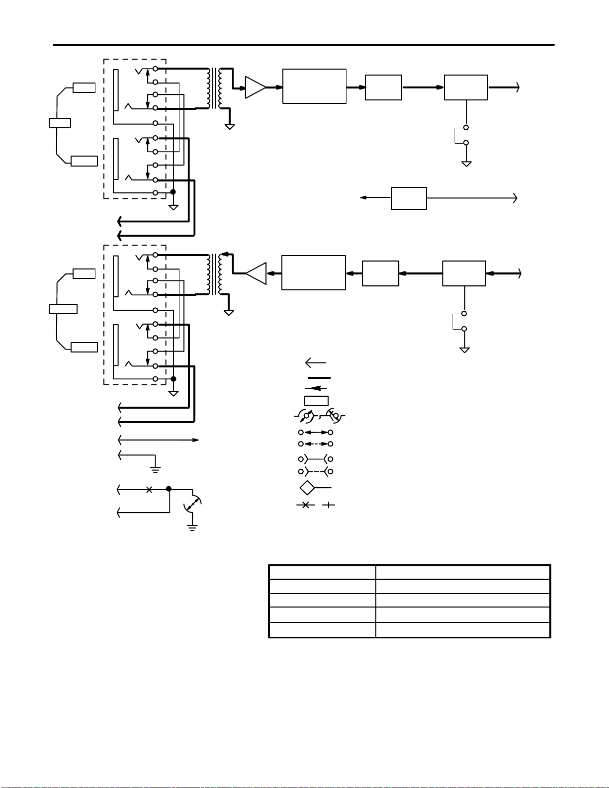
Figure 5. 3653–61 (Issue 6) 4W TO W/ER Block Diagram (Part 1 of 2)
Section 365-361-206
5
NOTES (CONTINUED):
+10
+ 7
0
16
22.5
INPUT (dBm) XMT GAIN (dB)
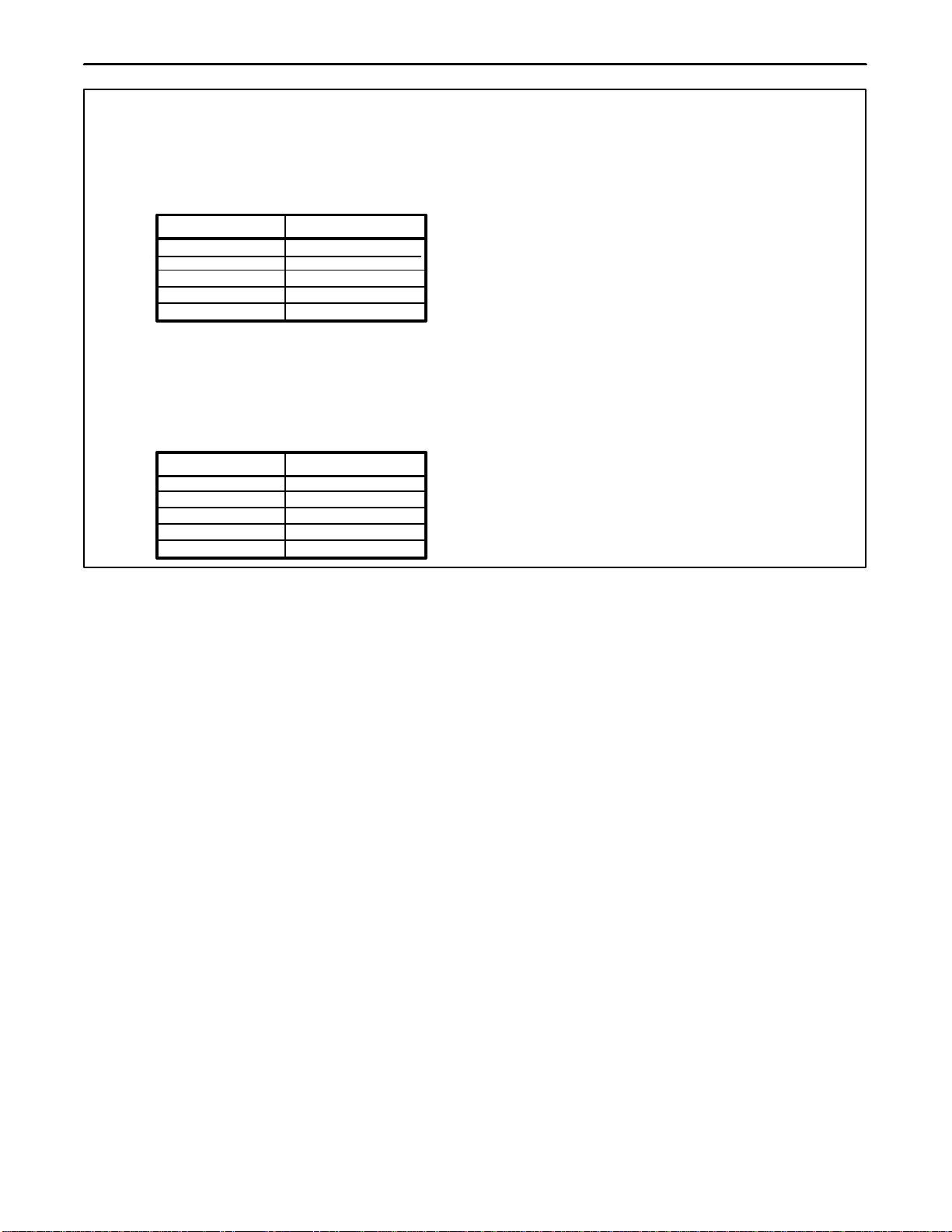
12. The XMT INPUT range at T&R: 22.5dBm to +10dBm. The
unit is factory adjusted for 16dBm input, with the XMT
gain set to 26dB.
0
3
10
26
32.5
+10
+ 7
0
16
22.5
OUTPUT (dBm) RCV GAIN (dB)
32.5
29.5
22.5
6.5
0
14. The RCV OUTPUT range at T1&R1: 22.5dBm to
+10dBm. The unit is factory adjusted for +7dBm output,
with the RCV gain set to 29.5dB.
13. The XMT PRESCRIPTION circuit provides 32.5dB gain in
0.1dB steps to compensate for input level variations. ReĆ
fer to the following table for details:
15. The RCV PRESCRIPTION circuit provides 32.5dB gain in
0.1dB steps to compensate for office wiring loss and outĆ
put level variations. Refer to the following table for details:
16. Trunk process relay is activated immediately due to an
alarm condition in the channel bank. Two seconds later it is
deactivated for 70 milliseconds and again activated. During
the activated mode, leads designated as 1 and 2 are
shorted:
Lead 2 Ground Close Y
Lead 2 Open Open Y
17. When the channel unit is removed from its mounting
slot, the lead designated 1" (pin 2) is grounded
through a shorting contact in the card connector.
18. When the channel unit is shipped from the factory the
default setting is for 7 5/6 bit encoding and decoding
and to send a busy" to the far end on both signaling
highways. For full 8Ćbit conversion, cut the jumper
wire at XC (encoding) and YC (decoding).
Figure 5. 3653–61 (Issue 6) 4W TO W/ER Block Diagram (Part 2 of 2)
4. CIRCUIT DESCRIPTION
Refer to Figure 5, the 3653–61 (Issue 6) block diagram, as needed while reading the following circuit description.
4.1 Transmit VF Path
VF signals applied to the input T&R (pins 50 and 48) are routed through the DROP and LINE lifting jacks to trans-
former T1. Transformer T1 provides a balanced input and dc isolation from the line.
Voice energy from transformer T1 is routed into the XMT GAIN and XMT PRESCRIPTION GAIN circuits which,
acting together, set the receive path gain to the exact level required to drive the XMT FILTER and ENCODER
circuits. The use of the XMT PRESCRIPTION GAIN allows finely controlled adjustment (0.1dB increments) for a
range of office TLPs from +10 to –22dBm.
The adjusted VF signal is then applied to the XMT FILTER circuit. The filter suppresses frequencies that are out-
side of the standard voice frequency and prevents them from entering the ENCODER. The ENCODER performs
an analog-to-digital (A/D) conversion of the VF signal before applying it to the XDATA lead for transmission to the
far end. The encoded bit stream can be selected for either a 7 5/6-bit or a full 8-bit encoding via wire jumper XC.
Selecting the 7 5/6-bit encoding sends a busy signal to the far end at all times. Selecting the full 8-bit encoding
provides for a greater signal-to-noise ratio.
4.2 Receive VF Path
The preselected 7 5/6-bit or full 8-bit digital signal transmitted from the far end is received by the 3653–61 via the
RDATA lead and is applied to the DECODER circuit. The DECODER performs a digital-to-analog (D/A) conver-
sion of the signal. To properly decode the information received, wire jumper YC is provided to match the decoding
scheme of the receive path to the scheme that was selected for the transmit path of the channel unit at the far
end. From the DECODER circuit, signals are passed to the RCV FILTER. The RCV FILTER suppresses frequen-
cies that are outside the bandwidth of the standard voice band.
The output of the RCV FILTER is applied to the RCV GAIN and RCV PRESCRIPTION GAIN circuits which, act-
ing together, set the receive path gain to the exact level required to interface with a range of office TLPs. The use

Section 365–361–206
6
of the RCV PRESCRIPTION GAIN allows finely controlled adjustment (0.1dB increments) for an output level from
+10 to –22dBm.
The adjusted VF signal is then buffered via the RCV GAIN circuit and routed through transformer T2 which pro-
vides dc isolation from the line and a balanced output level at T1&R1 (pins 8 and 7).
4.3 Lead Conditioning During CGA
The 3653–61 contains a TP (trunk processing) RELAY, which provides control to a set of dry contacts between
pins 2 and 6 (1-lead and 2-lead) of the module connector. During a carrier failure, the TP RELAY is activated via a
signal on the CGAW (carrier group alarm wink) lead which causes these contacts to close, wink open for 70 milli-
seconds after a 2.5 second delay, then close again. The 2-lead can be grounded (option Y) to provide a switched-
ground output on the 1-lead.
5. MOUNTING
The 3653–61 mounts in one channel unit slot of a 360/363 D4 terminal. The 3653–61 is equipped with an insert/
eject lever in the form of a hinged front panel which ensures a positive connection of the channel unit’s card-edge
connector to the backplane connector when the unit is installed. The insert/eject lever also facilitates removal of
the unit.
Installation and removal of modules should be done with care. Do not force a module into place. If
excessive resistance is encountered while installing a module, remove the module and check the
card guides and connector to verify proper alignment and the absence of foreign material.
CAUTION
Align the channel unit with the appropriate card-guided slot of the terminal. Slide the unit into the slot with the
front panel in a horizontal (up) position. When the top portion of the hinged front panel is under the front lip of the
terminal, push down on the front panel until it is in the vertical position. The channel unit’s card-edge connector
will begin to make contact with the inner portion of the backplane connector. Continue applying light pressure onto
the bottom edge of the front panel until the unit snaps into place.
6. INSTALLER CONNECTIONS
Installer connections are made to the channel unit by wire-wrapping leads onto the associated 50-pin connectors
located on the backplane assembly of the 360/363 D4 terminal. When installing a 3653–61 into a non-connecto-
rized 360/363 D4 terminal (00-suffixed), make the required connections to the T&R (pins 50 and 48), T1&R1 (pins
8 and 7), and the 1 and 2 leads (pins 2 and 6) of the appropriate connector. On connectorized 360/363 D4 termi-
nals (360–10, –11, etc.) connections are made via 25-pair female connectors (CINCH 222–22–50–023 or equiva-
lent) to the appropriate 25-pair male connectors of the 360/363 D4 terminal. Refer to Section 360–000–200 for
the wiring diagrams of the female connectors with respect to the 360/363 D4 terminal being used. Electrical con-
nections are made when the unit is installed.
7. OPTIONS
The following paragraphs describe the screw, jumper and switch options that are used to condition the 3653–61
for proper application and operation. Also refer to Figure 6 and Table 2 for a drawing showing the option locations
and a table summarizing the option conditioning requirements.
Note: When opening a screw option, rotate the screw counterclockwise two full turns to ensure that the connec-
tion is open. When closing a screw option, rotate the screw clockwise until it seats.

Section 365-361-206
7
1 2 3 4 5 6 7 8
O
N
O
N
1 2 3 4 5 6 7 8 9 10
RCV dB
MT dB
S4 S5
C
YC
Y
.1.2.4.8 124816
.1 .2 .4 .8 1 2 4 8 16
Jumper
wires
XC and YC
are actually
located on
the bottom
of the PCB
Figure 6. 3653–61 (Issue 6) 4W TO W/ER Option Locations and Optioning Summary
Table 2. Description of Figure 6
Option Function Position
S1, S2, S3 These designations not used on this module.
S4 and S5 Transmit and receive prescription gain controls. 0 to 32.5dB of gain can be
achieved in 0.1dB increments. See paragraph 7.1
YLead Conditioning (CGAW)
For a switched-ground output on pin 2 (1-lead) and an open on pin 6
(2-lead).
Open
For a ground on pin 6 (2-lead). Close
XC For an 8-bit encoding scheme in the transmit path and a greater signal-to-
noise ratio. Cut Jumper Wire
For a 7 5/6-bit encoding scheme in the transmit path and for transmitting a
busy signal to the far end. (Traditional D4 4TO operation.) Leave Jumper Wire
YC For an 8-bit decoding scheme in the receive path. Cut Jumper Wire
For a 7 5/6-bit decoding scheme in the receive path. Leave Jumper Wire
7.1 Switches S4 and S5 (Transmit and Receive Prescription Gain Control)
Switch S4 is an 8-section (four sections for transmit and four sections for receive) DIP switch that provides be-
tween 0 to 1.5dB of gain in 0.1dB increments to compensate for office wiring loss in the transmit and receive
paths. Switch S5 is a 10-section (five sections for transmit and five sections for receive) DIP switch that provides
between 0 to 31dB gain in 1dB increments for adjusting the transmit and receive paths to the proper operating
levels. By turning all switches in S4 and S5 to the ON position, a total of 32.5dB of gain can be achieved for each
path.
7.2 Screw Y (Lead Conditioning)
Screw Y determines the output of pins 2 and 6 during carrier failure trunk processing. If a switched-ground is re-
quired on pin 2 during carrier failure (TP RELAY activated), close screw Y. To provide a balanced (floating) con-
tact between pins 2 and 6, open screw Y.

Section 365–361–206
8
7.3 Wire Jumpers XC and YC ( 7 5/6-Bit or 8-Bit Encoding and Decoding)
Jumpers XC (transmit) and YC (receive) control the encoding and decoding scheme for the transmit and receive
paths to/from the facility and must be set to the same position for each direction. For a 7 5/6-bit encoding/decod-
ing scheme which provides the transmission of a constant busy signal to the far end and for end-to-end compati-
bility with E&M channel units, leave the jumper wires, XC and YC, in place. For a full 8-bit encoding/decoding
scheme which provides a greater signal-to-noise ratio than the 7 5/6-bit scheme and does not transmit a busy
signal to the far end, cut jumper wires XC and YC.
Note: If the encoding and decoding scheme cannot be determined, then choose the 7 5/6-bit scheme by leaving
the XC and YC jumper wires intact.
Note: When cutting the jumper wires, be sure to clip the jumper at each pad to completely remove the wire.
8. ALIGNMENT
The XMT GAIN switches (half of S4 and S5) are prescription controls that provide gain from zero to +32.5dB in
increments of 0.1dB to accommodate an input TLP range from +10 to –22.5dBm. To adjust the transmit path to
the proper operation level, the difference between +10 and the transmit TLP at T&R must be obtained:
[XMT GAIN = 10 –TLP]
For an input TLP of –2.0dBm, the XMT GAIN = 10 –(–2) = 12dB. Set the sum of the XMT switch settings on S4
and S5 to 12.
The RCV GAIN switches (half of S4 and S5) are prescription controls that provide gain from zero to +32.5dB in
increments of 0.1dB to accommodate an output TLP range from +10 to –22.5dBm. To adjust the receive path to
the proper operation level, the difference between –22.5 and the receive TLP at T1&R1 must be obtained:
[RCV GAIN = TLP –(–22.5)]
For an output TLP of –6.0dBm, the RCV GAIN = –6 –(–22.5) = 16.5dB. Set the sum of the RCV switch settings
on S4 and S5 to 16.5.
9. TESTING
Once optioning is fnished, place a call end-to-end through the facility to verify proper operation. If trouble is en-
countered, recheck all installer connections, options and alignment settings, and verify that the channel unit is
making positive connection to the backplane connector. If trouble persists, replace the unit with a similar unit
known to be in proper operating order and retest the facility. Channel unit testing for fault diagnosis or verification
of circuit operation is provided in Section 360–001–205.
10. TECHNICAL ASSISTANCE
If technical assistance is required, contact Charles Industries’Technical Services Center at:
847–806–8500
847–806–8556 (FAX)
800–607–8500
[email protected] (e-mail)
11. WARRANTY & CUSTOMER SERVICE
11.1 Warranty
Charles Industries, Ltd. offers an industry-leading, 5-year warranty on products manufactured by Charles Indus-
tries. Contact your local Sales Representative at the address or telephone numbers below for warranty details.
The warranty provisions are subject to change without notice. The terms and conditions applicable to any specific
sale of product shall be defined in the resulting sales contract.

Section 365-361-206
9
Charles Industries, Ltd.
5600 Apollo Drive
Rolling Meadows, Illinois 60008–4049
847–806–6300 (Main Office)
847–806–6231 (FAX)
11.2 Field Repairs (In-Warranty Units)
Field repairs involving the replacement of components within a unit are not recommended and may void the war-
ranty and compatibility with any applicable regulatory or agency requirements. If a unit needs repair, contact
Charles Industries, Ltd. for replacement or repair instructions, or follow the Repair Service Procedure below.
11.3 Advanced Replacement Service (In-Warranty Units)
Charles Industries, Ltd. offers an “advanced replacement”service if a replacement unit is required as soon as
possible. With this service, the unit will be shipped in the fastest manner consistent with the urgency of the situa-
tion. In most cases, there are no charges for in-warranty repairs, except for the transportation charges of the unit
and for a testing and handling charge for units returned with no trouble found. Upon receipt of the advanced re-
placement unit, return the out-of-service unit in the carton in which the replacement was shipped, using the pre-
addressed shipping label provided. Call your customer service representative at the telephone number above for
more details.
11.4 Standard Repair and Replacement Service (Both In-Warranty and Out-Of-Warranty Units)
Charles Industries, Ltd. offers a standard repair or exchange service for units either in- or out-of-warranty. With
this service, units may be shipped to Charles Industries for either repair and quality testing or exchanged for a
replacement unit, as determined by Charles Industries. Follow the Repair Service Procedure below to return units
and to secure a repair or replacement. A handling charge applies for equipment returned with no trouble found. To
obtain more details of this service and a schedule of prices, contact the CI Service Center at 217–932–5288 (FAX
217–932–2943).
Repair Service Procedure
1. Prepare, complete, and enclose a purchase order in the box with the equipment to be returned.
2. Include the following information:
–Company name and address
–Contact name and phone number
–Inventory of equipment being shipped
–Particulars as to the nature of the failure
–Return shipping address
3. Ship the equipment, purchase order, and above-listed information, transportation prepaid, to the ser-
vice center address shown below.
CI Service Center
Route 40 East
Casey, IL 62420–2054
4. Most repaired or replaced units will be returned within 30 or 45 days, depending on the product type
and availability of repair parts. Repaired units are warranted for either 90 days from the date of repair
or for the remaining unexpired portion of the original warranty, whichever is longer.
12. SPECIFICATIONS
12.1 Electrical
The electrical characteristics of the 3653–61 (Issue 6) are as follows:
(a) PERMISSIBLE MODES: 4N-4T, 4T-4N, 4T-4T.

Section 365–361–206
10
12.1.1. Electrical (End-to-End 7 5/6-Bit Operation)
(b) IMPEDANCE: 600 ohms, balanced.
(c) TRANSMIT AND RECEIVE LEVEL RANGES: +10 to –22.5dBm.
(d) LINE SIDE LEVELS:
Transmit (fixed): +5.2dBm TLP
Receive (fixed): +5.2dBm TLP
(e) ADJUSTABLE GAIN:
Transmit Minimum: 0.0dB
Maximum:+32.5dB
Step:0.1dB
Receive Minimum: 0.0dB
Maximum:+32.5dB
Step: 0.1dB
(f) TRANSMIT AND RECEIVE PATH FREQUENCY RESPONSE (Referenced at 1kHz):
Frequency (Hz) XMT (dB) RCV (dB)
60 -14 maximum —
200 -2 to 0.5 –1 to 0
300 +/–0.15 +/–0.15
1000 0 (REF) 0 (REF)
3000 +0.15 +0.15
3200 –0.75 to +0.15 –0.75 to +0.15
3400 -1.5 to 0 -1.5 to 0
4000 -14 maximum -14 maximum
4600 -32 maximum -32 maximum
(g) 1000Hz GAIN:
Transmit (fixed): –4.8dB
Receive (fixed): –27.7dB
(h) LOSS STABILITY: 0.5dB maximum of reference loss.
(i) LEVEL TRACKING: 0.25dB from +3 to –37dBm0; 0.5dB from –37 to –50dBm0.
(j) RETURN LOSS: 29dB minimum at 1kHz; 24dB minimum at 300 to 3000Hz.
(k) CROSSTALK (All modes):
Frequency (Hz) Single-Ended Level
1000 –71dBm0
2000 –70.5dBm0
3000 –70dBm0
(l) LONGITUDINAL BALANCE:
Frequency (Hz) AT&T Method (dB) IEEE Method (dB)
200 86 74
1000 80 74
3000 78 69

Section 365-361-206
11
(m) TRANSMIT/RECEIVE IDLE NOISE: 20dBrnC0, maximum.
(n) SIGNAL TO DISTORTION RATIO: 35dB minimum at 0 to –30dBm0; 29dB minimum at –40dBm0;
25dB minimum at –45dBm0.
(o) TRANSMIT AND RECEIVE SINGLE FREQUENCY DISTORTION: –40dB maximum from 0 to 4kHz;
–28dB maximum from 4kHz to 12kHz.
(p) TYPICAL CURRENT DRAIN AT –48Vdc: 19mA.
12.2 Physical
The physical characteristics of the 3653–61 are shown in Table 3.
Table 3. Physical Specifications
Feature U.S. Metric
Height 4.2 inches 10.6 centimeters
Width 1.35 inches 3.4 centimeters
Depth 10.3 inches 26.7 centimeters
Weight 9 ounces 255 grams
Operating Temperature 32 to 122F0 to 50C
Table of contents
Other Charles Network Hardware manuals


Popular Network Hardware manuals by other brands


Panasonic
Panasonic Schottky Barrier Diodes MA27D270G Specification sheet

Buffalo
Buffalo TeraStation iSCSI TS-RITGL/R5 user manual

Intellinet
Intellinet 561839 instructions

PairGain
PairGain PG-PLUS PLL-734 manual

Beckhoff
Beckhoff EJ6910 operating instructions

NETGEAR
NETGEAR SRX5308 - ProSafe® Quad WAN Gigabit SSL VPN... Configuration guide


