Charles 3650-01 User manual

Section 365–001–201
Equipment Issue 1
Fourth Printing, February 2000Telecommunications Group
2000Charles Industries Ltd.
CLEI is a trademark of Bell Communications Research, Inc.
All rights reserved. Printed in United States of America.
The availability of features and technical specifications herein subject to change without notice. Page 1 of 12
3650–01/03 2-Wire Equalized Transmission Only Channel
Units with Lead Conditioning (2W ETO w/LC
CONTENTS PAGE
Part 1. GENERAL 2. . . . . . . . . . . . . . . . . . . . . . . . . . . . . . . . . . . . . . . . . . . . . . . . . . . . . . . . . . . . . . . . . . . . . . . . . . . . .
Part 2. INSPECTION 2. . . . . . . . . . . . . . . . . . . . . . . . . . . . . . . . . . . . . . . . . . . . . . . . . . . . . . . . . . . . . . . . . . . . . . . . . . .
Part 3. APPLICATION GUIDELINES 3. . . . . . . . . . . . . . . . . . . . . . . . . . . . . . . . . . . . . . . . . . . . . . . . . . . . . . . . . . . . .
Part 4. CIRCUIT DESCRIPTION 3. . . . . . . . . . . . . . . . . . . . . . . . . . . . . . . . . . . . . . . . . . . . . . . . . . . . . . . . . . . . . . . . .
Part 5. MOUNTING 6. . . . . . . . . . . . . . . . . . . . . . . . . . . . . . . . . . . . . . . . . . . . . . . . . . . . . . . . . . . . . . . . . . . . . . . . . . . .
Part 6. INSTALLER CONNECTIONS 6. . . . . . . . . . . . . . . . . . . . . . . . . . . . . . . . . . . . . . . . . . . . . . . . . . . . . . . . . . . . .
Part 7. OPTIONS 7. . . . . . . . . . . . . . . . . . . . . . . . . . . . . . . . . . . . . . . . . . . . . . . . . . . . . . . . . . . . . . . . . . . . . . . . . . . . . .
Part 8. ALIGNMENT 9. . . . . . . . . . . . . . . . . . . . . . . . . . . . . . . . . . . . . . . . . . . . . . . . . . . . . . . . . . . . . . . . . . . . . . . . . . .
Part 9. TESTING 9. . . . . . . . . . . . . . . . . . . . . . . . . . . . . . . . . . . . . . . . . . . . . . . . . . . . . . . . . . . . . . . . . . . . . . . . . . . . . .
Part 10. TECHNICAL ASSISTANCE 9. . . . . . . . . . . . . . . . . . . . . . . . . . . . . . . . . . . . . . . . . . . . . . . . . . . . . . . . . . . . . .
Part 11. WARRANTY & CUSTOMER SERVICE 10. . . . . . . . . . . . . . . . . . . . . . . . . . . . . . . . . . . . . . . . . . . . . . . . . . .
Part 12. SPECIFICATIONS 11. . . . . . . . . . . . . . . . . . . . . . . . . . . . . . . . . . . . . . . . . . . . . . . . . . . . . . . . . . . . . . . . . . . . .
Figure 1. 3650–01 2W ETO w/LC Channel Unit

Section 365–001–201
2
1. GENERAL
1.1 Document Purpose
This document provides a general, circuit, installation and testing information for the Charles Industries
3650–01/03 2-Wire ETO w/LC Channel Units
1.2 Document Status
This document is reprinted to provide a general editorial update.
1.3 Equipment Function
The Charles Industries 3650-01/03 2-Wire ETO w/LC Channel Units are used in the CHarles Industries 360/363
D4 Digital Carrier Terminal to provide an interface to in-band (with no DC) signaling or no signaling special service
units such as 2-wire voice frequency extensions, data sets, or modems on a private line. The 3650–01 provides a
900-ohm balanced interface, while the 3650–03 provides a 600-ohm balanced interface. The 3650–01 is shown in
Figure 1.
1.4 Equipment Location/Mounting
This unit occupies one channel unit slot of a Charles Industries 360/363 D4 Digital Carrier Terminal Channel Bank
assembly.
1.5 Equipment Features
The 3650–01/03 2-Wire ETO w/LC Channel Units include the following features:
Termination impedance of 2.15 uF in series with 900 ohms (3650–01) or 600 ohms (3650–03) for
matching the impedance of the 2-wire port interface.
Built-in selectable hybrid-balancing compromise network of 2.15 uF in series with 900 ohms
(3650–01) or 600 ohms (3650–03)
Built-in jack (J3) to mount an optional 3690–00/10 compromise network subassembly or an optional
3690–01/11, 02/12, or 03/13 precision balance network (PBN) subassembly, and provisions (pins 41
and 46) to connect an external PBN.
Built in jacks (J2 and J4) to mount optional 3691–00 nonloaded cable equalizer and/or 3691–01 H88
loaded cable equalizer subassemblies for post- and/or pre-equalization.
Transmit and receive prescription attenuation of 16.5 dB in 0.1 dB increments.
Sealing current for internal, external or looped feed.
Carrier group alarm, ground or shorting contact, with wink for lead conditioning.
68 dB of gain transfer, eliminating the need for external VF amplifiers.
Selectable full 8-bit coding for optimum signal-to-distortion ratio.
Front-panel-accessible bantam-breaking jacks for accessing the distant (line) or local (drop) end.
2. INSPECTION
2.1 Inspect for Damages
Inspect the equipment thoroughly upon delivery. If the equipment has been damaged in transit, immediately re-
port the extent of damage to the transportation company.
2.2 Equipment Identification
Charles Industries’ equipment is identified by a model and issue number imprinted on the front panel or located
elsewhere on the equipment. Each time a major engineering design change is made on the equipment, the issue

Section 365-001-201
3
number is advanced by 1 and imprinted on subsequent units manufactured. Therefore, be sure to include both
the model number and its issue number when making inquiries about the equipment.
2.3 Static Concerns
Each module is shipped in static-protective packaging to prevent electrostatic charges from damaging static-sen-
sitive devices. Use approved static-preventive measures, such as static-conductive wrist straps and a static-dissi-
pative mat, when handling modules outside of their protective packaging. A module intended for future use should
be tested as soon as possible and returned to its original protective packaging for storage.
Do not ship or store modules near strong electrostatic, electromagnetic, or magnetic fields. Use the
original static-protective packaging for shipping or storage.
CAUTION
3. APPLICATION GUIDELINES
The 3650-01/03 channel units provide a voice path without signaling. Typical applications are for private line data
services requiring a metallic facility extension, tandem circuits employing inband signaling such as SF circuits,
and other applications where voice transmission without signaling is required. See Figure 2 for a typical applica-
tion.
360/363
D4
T
E
R
M
I
N
A
L
2W ETO
3650-
01/03
STATION
EQUIP-
MENT
TCXR Facility
+6 to –10.5 dBm
METALLIC FACILITY
–9.5 to +7 dBm
Figure 2. 3650–01/03 2W ETO w/LC Channel Unit Typical Application
4. CIRCUIT DESCRIPTION
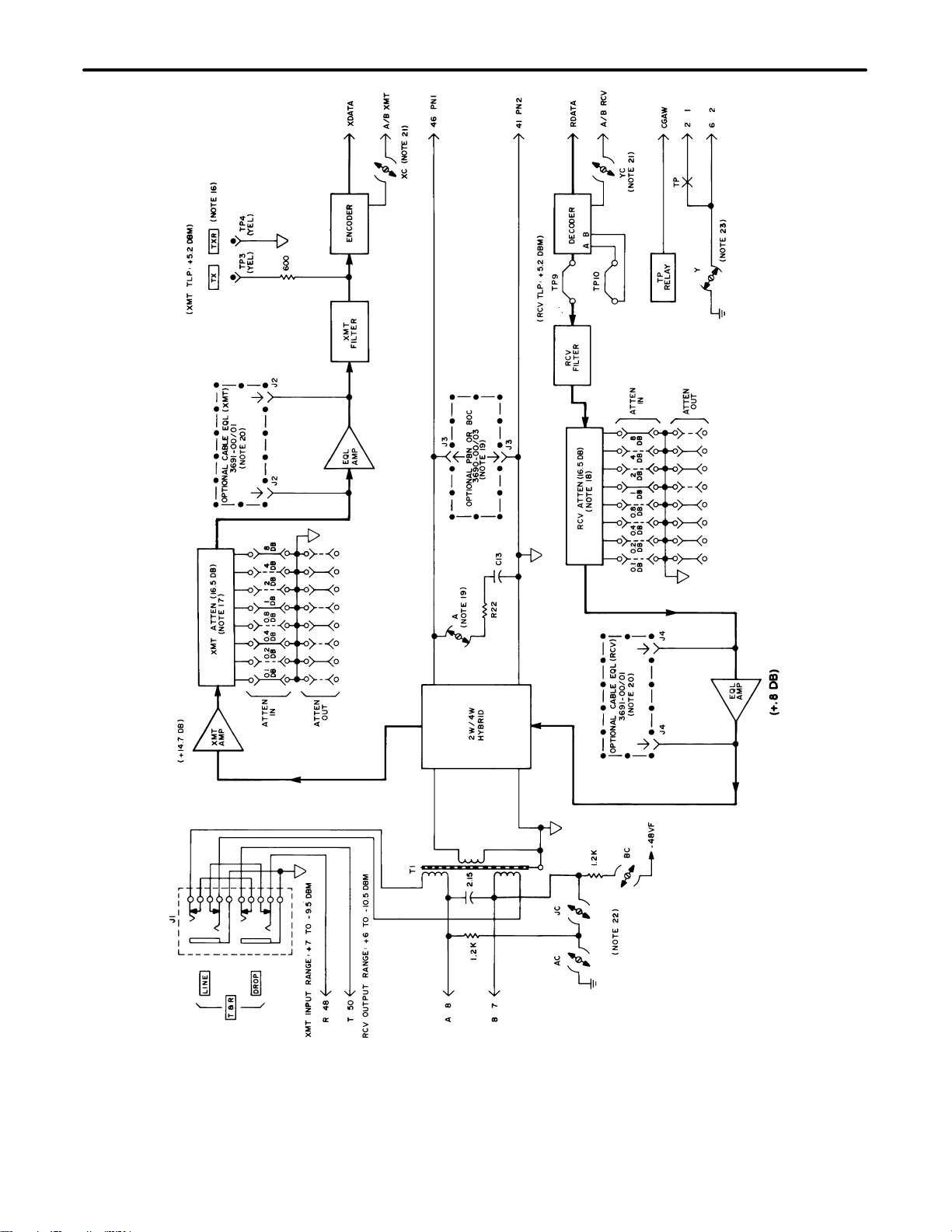
Refer to the block diagram in Figure 3 while reading the following circuit description.
4.1 Transmit VF Path
VF signals applied to the input tip and ring leads (pins 50 and 48) are routed through the DROP and LINE break-
ing jacks to transformer T1. In turn, transformer T1 provides DC isolation from the metallic facility and accepts
input signals from –9.5 to +7 dBm. After passing through the 2W/4W hybrid, the VF signals are routed to the XMT
AMP. This circuit amplifies the signal to compensate for losses in the transformer and filters.
From the XMT AMP, signals pass to the XMT ATTEN circuit, which is adjusted to provide the proper signal level
to the encoder. Adjustment is accomplished via push-on jumpers which provide up to 16.5 dB attenuation in 0.1
dB increments. The output of the XMT ATTEN is forwarded to the EQL AMP. The EQL AMP, in conjunction with
an optional equalizer subassembly, provides amplitude post-equalization for non-loaded or loaded cable.
The adjusted VF signal is then applied to the XMT filter, which suppresses frequencies outside the bandwidth of
the standard voice frequency and prevents them from entering the encoder.
The filtered VF signal is then applied to the encoder. Access to the signals at the encoder input is provided by
jacks TX and TXR. The nominal level at this point it +5.2 +/–0.1 dBm (measured with a 600-ohm bridged meter).
During the encode command pulse on the ECM lead, analog signals present at the input of the encoder are con-
verted to digital signals. The digital data stored in the encoder is transmitted on the XDATA lead.
Section 365–001–201
4
Figure 3. Block Diagram

Section 365-001-201
5
Table 1. Notes for Figure 3
# Note # Note
1. Connector 13. XMT input range at tip and ring: +7 dBm to –7.5 dBm. The unit is
factory adjusted for 0 dBm input. The XMT ATTEN is set for 9.5
dB attenuation.
2. Primary transmission path 14. RCV output range at tip and ring: +6 dBm to –10.5 dBm. The
unit is factory adjusted for –3 dBm output. The RCV ATTEN is
set for 9.0 dB attenuation.
3. PC mount test point 15. Models: 3650–01 900 ohm w/LC
3650–03 600 ohm w/LC
4. Signal flow direction 16. The level at the transmit unbalanced monitor points TX–TXR.
Measured with a bridged meter, should be +5.2 dBm +/–0.1 dB.
5. N.O., N.C. relay contacts 17. The XMT ATTEN provides 16.5 dB attenuation in 0.1 dB steps
to accommodate input range of from +7 dBm to –9.5 dBm. With
–9.5 dBm input, no attenuation is needed. When input goes up,
an appropriate amount of attenuation is added so that the level
at TX–TXR is maintained at +/–5.2 dBm to +0.1 dB.
6. Front panel marking 18. The RCV ATTEN provides 16.5 dB attenuation in 0.1 dB steps to
accommodate output range of from +6 dBm to –10.5 dBm. With 6
dBm output, no attenuation is needed. An appropriate amount of
attenuation is added when a lower output level is required.
7. Optional circuit enclosure 19. A91–369000/03PBN/BOC are ordered separately and used when
inserted into connector J3. Open option A when PBN/BOC is used.
8. Receptacletype, optional strap
Alternate position 20. A91–369100nonloaded cable equalizer or a A91–369101 loaded
cable equalizer is ordered separately to provide post-equalization
when inserted into connector J2, and pre-equalization when in-
serted into connector J4.
9. Open, closed screw option 21. For full 8-bit conversion, open screw options XC (encoding) and
YC (decoding). For 7 5/6 bit encoding and to send a busy to the
far end on both signaling highways close option XC. Similarly,
for 7 5/6 bit decoding, close option YC.
10. Coil type test point 22. Screw options AC, BC and JC are used to provide sealing cur-
rent.
Close Option Open Option Function
AC, BC JC Supply sealing current to the
loop.
JC AC, BC Complete the path when seal-
ing current is supplied from the
far end of the loop.
11. Ganged switches are indicated by dashed connection line or
suffixed reference designation. 23. The trunk processing relay (TP) is activated immediately upon
an alarm condition in the channel bank. Approximately 2 sec-
onds later it is deactivated for 70 milliseconds During the acti
12. PC mount test jacks: onds later it is deactivated for 70 milliseconds. During the acti-
vated mode, leads designated as 1 and 2 are shorted. Lead 2
Marking Function
vated
mode
,
leads
designated
as
1
and
2
are
shorted
.
Lead
2
can be grounded by screw option Y. When the channel unit is
removed from the mounting slot, the
“
1
”
lead (
p
in 2) is con
-
T&R Line (J1–A) Access towards channel unit
removed
from
the
mounting
slot
,
the
“1”
lead
(pin
2)
is
con
-
nected to ground through a shorting contact in the backplane
card connector
T&R drop (J1–B) Access towards office equip-
ment
ggg
card connector.
TX&TXR (TP3 & TP4) 4-wire XMT monitor
4.2 Receive VF Path
Digital data on the RDATA lead is read into the decoder, which provides digital-to-analog conversion.
The output of the decoder is applied to the RCV filter. The RCV filter reconstructs the transmitted waveform from
the stair-step output of the decoder and suppresses frequencies above 4kHz.
From the RCV filter, signals pass to the RCV ATTEN circuit, which is adjusted to provide the required output level
at the 2-wire pair. Adjustment is accomplished via push-on jumpers which provide up to 16.5 dB attenuation in 0.1
dB increments. The output of the RCV ATTEN is forwarded to the EQL AMP. The EQL AMP, in conjunction with
an optional equalizer subassembly, provides amplitude pre-equalization for nonloaded or loaded cable.
The output of the EQL AMP is applied through the 2W/4W hybrid to transformer T1 and to tip and ring (pins 48
and 50).

Section 365–001–201
6
4.3 Trunk Processing During a Carrier Group Alarm (CGA)
Upon carrier failure, the CGAW bus goes to ground immediately; it then winks open for 70 milliseconds approxi-
mately 2.5 seconds later. The CGAW bus controls the TP relay which controls the status of the 1 (pin 2) and 2
(pin 6) lead pins. The TP relay operates when CGAW goes to ground and releases for for 70 milliseconds when
CGAW winks open; it then remains operated for the duration of trunk processing. When the TP relay operates, it
shorts the 1 and 2 leads together. The 2 lead can be tied to ground by setting screw option Y closed. When the
channel unit is removed from its mounting slot, the 1 lead is connected to ground through a shorting contact in the
backplane connector.
5. MOUNTING
The 3650–01/03 mounts in one channel unit slot of a 360/363 D4 terminal. The hinged front panel serves as an
insert lever to ensure a positive connection of the channel unit’s card-edge connector to the backplane connector
when the unit is installed and as an eject lever when the module is taken out of service.
Never handle or carry the channel unit by using the front panel in its open (upward) position.
CAUTION
Install and remove the module with care. Do not force it into place. If excessive resistance is
encountered while installing the module, remove it and check the card guides and connector to
verify proper alignment and the absence of foreign material.
CAUTION
Use the following steps to mount the unit:
Step Action
1. Align the channel unit with the appropriate card-guided slot of the terminal.
2. Slide the unit into the slot with the front panel in the horizontal (up)position.
3. When the top portion of the hinged front panel is under the front lip of the terminal, push down on the
front panel until it is in the vertical position. The channel unit’s card-edge connector will begin to make
contact with the backplane connector.
4. Continue to apply light pressure to the bottom edge of the front panel until the unit snaps into place.
6. INSTALLER CONNECTIONS
6.1 Non-Connectorized Terminal
Installer connections are made to the 3650–01/03 channel unit by wire-wrapping to the T and R leads (pins 50
and 48), the make-busy leads 1 and 2 (pins 2 and 6) and, as required, the sealing current A and B (pins 8 and 7)
leads and/or the PN1 and PN2 (pins 46 and 41) leads of the associated 50-pin connectors on the backplane as-
sembly of a non-connectorized 360/363 D4 terminal.
6.2 Connectorized Terminal
On connectorized 360/363 D4 terminals, (360–10, –11, etc.) connections are made via 25-pair female connectors
(CINCH 222–22–50–023 or equivalent) to the appropriate 25-pair male connectors of the 360/363 D4 terminal.
Refer to section 360–000–200 for the wiring diagrams of the female connectors with respect to the 360/363 D4
terminal being used. Electrical connections are made when the unit is installed; PN1 and PN2 are not connecto-
rized.

Section 365-001-201
7
7. OPTIONS
The following paragraphs describe the connecting jacks, push-on jumper options, and screw options that are
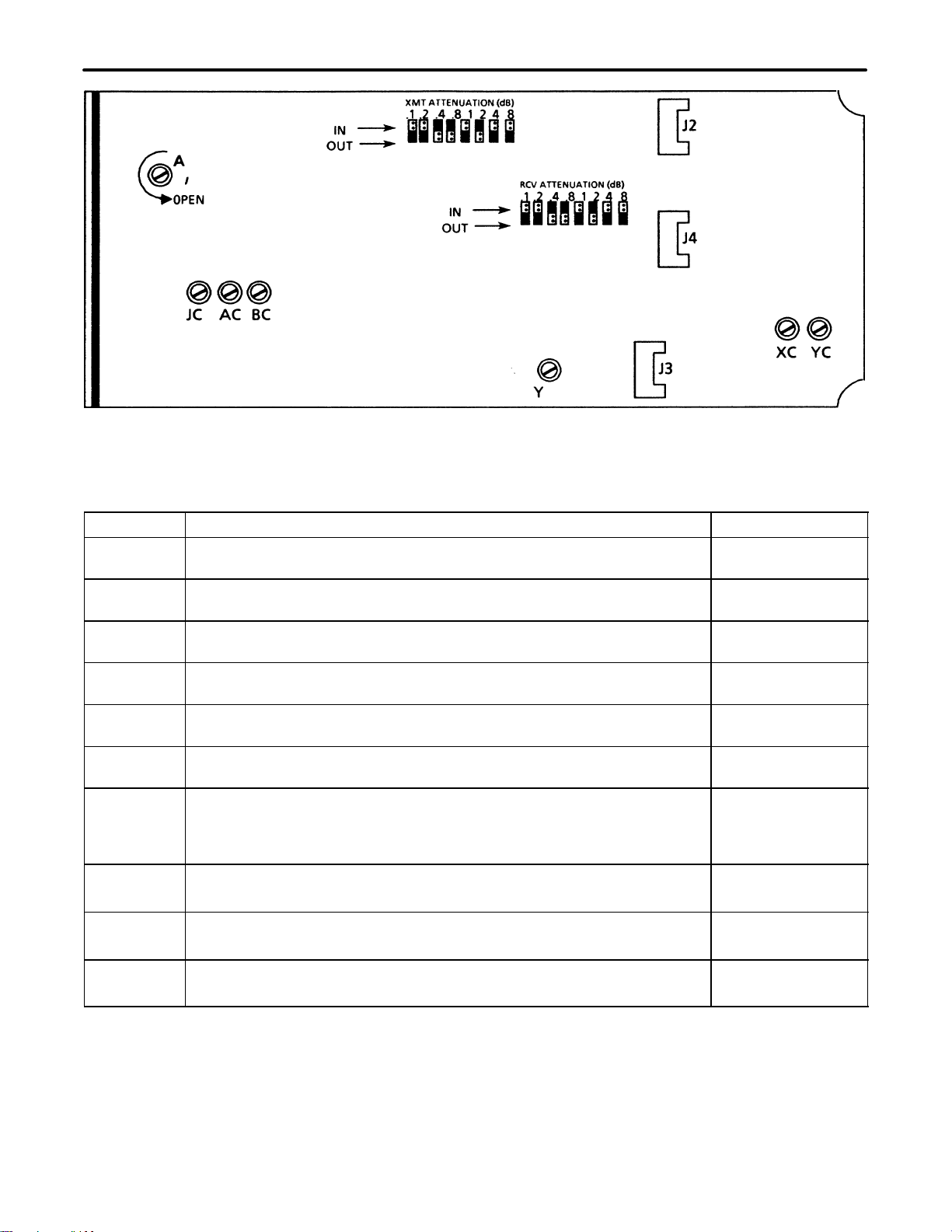
used to condition the 3650–01/03 for proper application and operation. Also refer to Figure 4 for an illustration of
the connecting jack and option locations and to Table 2 for a brief summary of the option conditioning require-
ments.
Note: When opening a screw option, rotate the screw counterclockwise two full turns to ensure that the connec-
tion is open. When closing a screw option, rotate the screw clockwise until it seats. When selecting the
push-on jumper options, push the jumper over the appropriate pins with that option grouping to obtain the
desired operation.
7.1 Post-Equalization (J2)
A Charles Industries 3691–00 Nonloaded Cable Equalizer Subassembly or 3691–01 H88 Loaded Cable Equalizer
Subassembly can be ordered separately to provide post-equalization (transmit path) when inserted into jack J2.
Additional information about the equalizer is available in the 3691–XX documentation.
7.2 Comp Net/PBN—Hybrid Balancing (J3)
A Charles Industries 3690–00/10, –01/11, –02/12, or –03/13 BPN Subassembly can be ordered separately and
inserted into jack J3 to provide hybrid balancing. Refer to the 3690–XX documentation for more information.
7.3 Pre-Equalization (J4)
A Charles Industries 3691–00 Nonloaded Cable Equalizer subassembly or 3691–01 H88 Loaded Cable Equalizer
subassembly can be ordered separately to provide pre-equalization (received path) when inserted into jack J4.
Refer to the 3691–00/01 document for additional information.
7.4 XMT Attenuation (push-on jumpers)
Eight push-on jumpers select up to 16.5 dB attenuation in 0.1 dB increments for adjusting the transmit path to the
proper operating level. By placing each jumper (0.1, 0.2, 0.4, 0.8, 1, 2, 4, 8 dB) to the IN position, as required, a
level of +5.2 dBm at the TX and TXR test points can be achieved. Placing all of the jumpers in the OUT position
results in 0 dB attenuation.
7.5 RCV Attenuation (push-on jumpers)
Eight push-on jumpers select up to 16.5 dB attenuation in 0.1 dB increments for adjusting the receive path to the
proper operating level. By placing each jumper (0.1, 0.2, 0.4, 0.8, 1, 2, 4, 8 dB) to the IN position, as required, the
desired output level can be achieved. Placing all of the jumpers in the OUT position results in 0 dB attenuation.
7.6 Hybrid Balance (Screw Option A)
The 3650–01/03 can accept an internal PBN or BOC via connector J3 or an external PBN or BOC via pins 46 and
41 (PN1 and PN2 respectively). Open option A to condition the unit to use an optional PBN or OBC. Closing op-
tion A when an optional PBN or BOC is not being used selects the on-board compromise network of 900/600
ohms in series with 2.15 uF.
7.7 Sealing Current (screw options AC, BC, JC)
Sealing current is a direct current that prevents contact deterioration, reducing poor-contact noise in non-soldered
cable splices. It is used on metallic lines carrying data, carrier, or other services employing low-level AC signals
not superimposed on a direct current. Sealing currents can be provided externally or internally (from the channel
unit); it can also be looped back when the distant end provides the sealing current source.
Sealing current is provided externally (customer supplied Charles Industries 8491–00 or equivalent connected to
pins 7 and 8) on the A and B leads by opening screws JC, AC, and BC. Use these settings also if sealing current
is NOT used on the metallic facility. When sealing current is provided from the far end of the 2W metallic facility,
close screw JC (to complete the loop) and open screws AC and BC. To use the on-board source of –48VDC seal-
ing current, open screw JC and close screws AC and BC.
7.8 Lead-Conditioning (screw option Y)
During an alarm, trunk processing is implemented on the 1 and 2 leads (pins 2 and 6, respectively) to the interfac-
ing trunk or switching system as follows: busy condition immediately upon an alarm, with a 70-millisecond wink
idle occurring 2.5 seconds after the alarm.
Section 365–001–201
8
Figure 4. 3650–01/03 ETO w/LC Options
Table 2. 3650–01/03 ETO w/LC Option Description
Option Function/Remarks Position
J2 Jack for mounting an optional transmit post-equalizer (3691–00/01). See documentation
for 3691–00/01
J3 Jack for mounting optional compensation network/PBN 3690–00/10,
–01/11, –02/12, or –03/13. See documentation
for 3690–XX
J4 Jack for mounting an optional receive pre-equalizer 3691–00/01 See documentation
for 3691–00/01
XMT ATTEN Eight push-on jumpers (0.1, 0.2, 0.4, 0.8, 1, 2, 4, 8) total 16.5 dB of trans-
mit attenuation when all jumpers are in the IN position. See part 7.4
RCV ATTEN Eight push-on jumpers (0.1, 0.2, 0.4, 0.8, 1, 2, 4, 8) total 16.5 dB of re-
ceive attenuation when all jumpers are in the IN position. See part 7.5
A Set to the OPEN position if jack J3 is equipped or if an external PBN/BOC
is used. Open/Closed
AC, BC, JC For external sealing current at pins 7 and 8 (or no SC) open JC, AC, and
BC. For looping sealing current from the 2W line, close JC and open AC
and BC. For supplying –48 VDC sealing current to the 2W line, open JC
and close AC and BC.
Open/Closed
Y1 lead/2 lead floating dry contact closure during trunk processing.
Ground on 1 lead during trunk processing. Open
Closed
XC Full 8-bit encoding.
7 5/6 bit encoding. Open
Closed
YC Full 8-bit encoding.
7 5/6 bit encoding. Open
Closed
Screw option Y conditions the 1 and 2 leads for the proper trunk or switching system interface. For a dry-contact
closure of the 1 and 2 leads during trunk processing, open screw Y. For a ground on the 1 lead (pin 2) during
trunk processing, close option Y.

Section 365-001-201
9
7.9 Full Bit Encoding/Decoding (screw options XC, YC)
Screw options XC and YC condition the channel unit for either full 8-bit encoding/decoding (no signaling) or 7 5/6
bit encoding/decoding (busy condition transmitted to far end). For full 8-bit decoding, open screw YC. For 7 5/6 bit
decoding, close screw YC. The 8-bit encoding and decoding provides a better signal-to-noise ratio than the 7 5/6
bit encoding and decoding.
8. ALIGNMENT
8.1 Transmit Alignment
The XMT attenuation push-on jumpers provide attenuation from 0 to 16.5 dB in increments of 0.1 dB to accom-
modate an input TLP range from –9.5 to +7 dBm. To adjust the transmit path to the proper operating level, the
difference between –9.5 and the transmit TLP and tip and ing must be calculated.
[XMT ATTN = TLP–(–9.5)]
For an input TLP of 7 dBm, the XMT ATTN = 7–(–9.5) = 16.5 dB. Se the sum of the push-on jumpers to 16.5 (all
to the IN position).
8.2 Receive Alignment
The RCV attenuation push-on jumpers provide attenuation from 0 to 16.5 dB in increments of 0.1 dB to accom-
modate an output TLP range from +6 to –10.5 dBm. To adjust the receive path to the proper operating level, the
difference between +6 and the receive TLP at T1 and R1 must be obtained.
[RCV ATTN = +6–TLP]
For an output TLP of –12.5 dBm, the RCV ATTN=+6–(–10.5) = 16.5 dB. Set the sum of the push-on jumpers to
16.5 (all to the IN position).
9. TESTING
After mounting, installation, optioning and alignment, use the following steps to test the unit.
Step Action
1. Place a call end-to-end through the facility to verify proper operation.
2. If trouble is encountered, re-check all installer connections, options and alignment settings and verify
that the channel unit is making positive connections to the backplane connector. Then re-test.
3. If trouble persists, replace unit with a similar unit known to be in operating order and retest the facility.
Channel unit testing for fault diagnosis or verification of circuit operation is provided in section
360–001–20X.
10. TECHNICAL ASSISTANCE
10.1 Technical Assistance — U.S.
If technical assistance is required, contact Charles Industries’ Technical Services Center at:
847–806–8500
847–806–8556 (FAX)
800–607–8500
[email protected] (e-mail)
10.2 Technical Assistance — Canada
Canadian customers contact:
905–821–7673 (Main Office)
905–821–3280 (FAX)

Section 365–001–201
10
11. WARRANTY & CUSTOMER SERVICE
11.1 Warranty
Charles Industries, Ltd. offers an industry-leading, 5-year warranty on products manufactured by Charles Indus-
tries. Contact your local Sales Representative at the address or telephone numbers below for warranty details.
The warranty provisions are subject to change without notice. The terms and conditions applicable to any specific
sale of product shall be defined in the resulting sales contract.
Charles Industries, Ltd.
5600 Apollo Drive
Rolling Meadows, Illinois 60008–4049
847–806–6300 (Main Office)
847–806–6231 (FAX)
11.2 Field Repairs (In-Warranty Units)
Field repairs involving the replacement of components within a unit are not recommended and may void the war-
ranty and compatibility with any applicable regulatory or agency requirements. If a unit needs repair, contact
Charles Industries, Ltd. for replacement or repair instructions, or follow the
Repair Service Procedure
below.
11.3 Advanced Replacement Service (In-Warranty Units)
Charles Industries, Ltd. offers an “advanced replacement” service if a replacement unit is required as soon as
possible. With this service, the unit will be shipped in the fastest manner consistent with the urgency of the situa-
tion. In most cases, there are no charges for in-warranty repairs, except for the transportation charges of the unit
and for a testing and handling charge for units returned with no trouble found. Upon receipt of the advanced re-
placement unit, return the out-of-service unit in the carton in which the replacement was shipped, using the pre-
addressed shipping label provided. Call your customer service representative at the telephone number above for
more details.
11.4 Standard Repair and Replacement Service (Both In-Warranty and Out-Of-Warranty Units)
Charles Industries, Ltd. offers a standard repair or exchange service for units either in- or out-of-warranty. With
this service, units may be shipped to Charles Industries for either repair and quality testing or exchanged for a
replacement unit, as determined by Charles Industries. Follow the
Repair Service Procedure
below to return units
and to secure a repair or replacement. A handling charge applies for equipment returned with no trouble found. To
obtain more details of this service and a schedule of prices, contact the CI Service Center at 217–932–5288 (FAX
217–932–2943).
Repair Service Procedure
1. Prepare, complete, and enclose a purchase order in the box with the equipment to be returned.
2. Include the following information:
– Company name and address
– Contact name and phone number
– Inventory of equipment being shipped
– Particulars as to the nature of the failure
– Return shipping address
3. Ship the equipment, purchase order, and above-listed information, transportation prepaid, to the ser-
vice center address shown below.
CI Service Center
Route 40 East
Casey, IL 62420–2054
4. Most repaired or replaced units will be returned within 30 or 45 days, depending on the product type
and availability of repair parts. Repaired units are warranted for either 90 days from the date of repair
or for the remaining unexpired portion of the original warranty, whichever is longer.

Section 365-001-201
11
12. SPECIFICATIONS
12.1 Electrical (Single-Ended)
(a) Transmit input TLP range: –9.5 to +7 dBm
(b) Receive output TLP range: –10.5 to +6 dBm
(c) Transmit prescription attenuation: 0 to 16.5 dB in increments of 0.1 dB
(d) Receive prescription attenuation: 0 to 16.5 dB in increments of 0.1 dB
(e) Transmit and receive port impedance: 3650–01, 900 ohms + 2.15 uF; 3650–02, 600 ohms + 2.15 uF
(f) Transmit and receive path frequency response (referenced at 1kHz):
Frequency (Hz) XMT (dB) RCV (dB)
60 –20 minimum –
200 –2.5 to 0 –1.5 to 0
300 –0.49 to +0.24 –0.49 to +0.24
1000 0 (ref) 0 (ref)
3000 –0.49 to +0.24 –0.49 to +0.24
3400 0 to –1.2 0 to –1.2
4000 –14 minimum –14 minimum
5100 –32 minimum –32 minimum
(g) Longitudinal balance: –62 dB or less at 200 Hz to 1 kHz; –60 dB or less at 3 kHz
(h) Signal to distortion ratio: 35 dB minimum at 0 to –30 dBm0; 29 dB minimum at –40 dBm0; 25 dB
minimum at –45 dBm0
(i) Trans-hybrid loss: Echo return loss, 36 dB minimum; singing return loss, 25 dB minimum; singing re-
turn loss high, 32 dB minimum
(j) Return loss: Echo return loss, 35 dB minimum; singing return loss, 23 dB minimum; singing return
loss high, 32 dB minimum
(k) Transmit/receive idle channel noise: 20 dBrnC0 maximum
(l) Crosstalk: 61 dBm0 minimum at 400 Hz, 71 dBm0 minimum at 700 Hz to 1 kHz, 70 dBm0 minimum
at 3 kHz
(m) Level tracking (measured single-ended at 1010 Hz): +/–0.25 dB from +3 to –37 dBm0, +/–0.5 dB
from –38 to –50 dBm0

Section 365–001–201
12
12.2 Physical
Physical specifications are shown in Table 3.
Table 3. Physical Specifications
Feature U.S. Metric
Height 4.2 inches 10.6 centimeters
Width 1.35 inches 3.4 centimeters
Depth 10.3 inches 26.7 centimeters
Weight 16 ounces 455 grams
Temperature 32to 122F 0to 50C
This manual suits for next models
1
Table of contents
Other Charles Network Hardware manuals


