DEUTA Controls EnOcean EnoDisc User manual
Manual Page 1 of 32
© DEUTA Controls GmbH Paffrather Str. 140, 51465 Bergisch Gladbach Tel.:+49 2202 285 57- 61
14.07.2021 Hauptstraße 76, 32479 Hille Tel: +49 5734 51466 - 0
Technical data might change info@deuta-controls.de; www.deuta-controls.net Fax:+49 5734 51466 - 28
AL-512-00-902 IP-EnOcean-Bridge PoE V1
Ethernet to EnOcean Interface – EnoDisc®
EnOcean 902 MHz
Part no. 12395
Version 1.12, valid since FW/HW 2.0 / 1.0

AL-512-00-902 IP-EnOcean-Bridge PoE V1
Product manual Page 2 of 32
© DEUTA Controls GmbH Paffrather Str. 140, 51465 Bergisch Gladbach Tel.:+49 2202 285 57- 61
14.07.2021 Hauptstraße 76, 32479 Hille Tel: +49 5734 51466 - 0
Technical data might change info@deuta-controls.de; www.deuta-controls.dnet Fax:+49 5734 51466 - 28
© 2021 DEUTA Controls GmbH
All rights reserved
This Manual, including all figures and illustrations, is copyright-protected. Any further use of
this Manual by third parties that violate pertinent copyright provisions is prohibited.
Reproduction, translation, electronic and phototechnical filing/archiving (e.g., photocopying)
as well as any amendments require the written consent of DEUTA Controls GmbH, Bergisch
Gladbach, Germany. Non-observance will involve the right to assert damage claims.
DEUTA Controls GmbH
Paffrather Straße 140
51465 Bergisch Gladbach
Phone:+49 2202 28557-61
Fax: +49 2202 28557-79
E-Mail: info@deuta-controls.de
Web: www.deuta-controls.net
Every conceivable measure has been taken to ensure the accuracy and completeness of this
documentation. However, as errors can never be fully excluded, we always appreciate any
information or suggestions for improving the documentation.
E-Mail: info@deuta-controls.de

AL-512-00-902 IP-EnOcean-Bridge PoE V1
Product manual Page 3 of 32
© DEUTA Controls GmbH Paffrather Str. 140, 51465 Bergisch Gladbach Tel.:+49 2202 285 57- 61
14.07.2021 Hauptstraße 76, 32479 Hille Tel: +49 5734 51466 - 0
Technical data might change info@deuta-controls.de; www.deuta-controls.dnet Fax:+49 5734 51466 - 28
Table of Contents
1Validity of this documentation......................................................................................... 5
2Intended use .................................................................................................................. 5
3Disposal ......................................................................................................................... 5
4Device description .......................................................................................................... 5
4.1 Functionality........................................................................................................... 5
4.2 External product interface ...................................................................................... 6
4.3 Observe intended use............................................................................................ 6
4.4 Observe statutory provisions for operating frequency range................................... 6
4.5 Non-conduction mounting surface.......................................................................... 6
5Technical data................................................................................................................ 7
5.1 Communication / EnOcean wireless interface ........................................................ 7
5.2 Communication / Ethernet interface ....................................................................... 7
5.3 User interfaces....................................................................................................... 7
5.4 Housing / connection technology ........................................................................... 7
5.5 Power supply ......................................................................................................... 7
5.6 Environmental conditions ....................................................................................... 8
5.7 Dimensions and weight .......................................................................................... 8
5.8 Approvals............................................................................................................... 8
5.9 Standards and guidelines....................................................................................... 8
6Functional description in detail ....................................................................................... 9
6.1 Receiving and transmitting of EnOcean data, and transfer in ESP3 format............ 9
7The EnoDisc®webserver...............................................................................................10
7.1 “Home” / EnoDisc device info page.......................................................................10
7.2 “EnOcean” / EnOcean data monitor ......................................................................10
7.3 “Repeater” / EnOcean repeater configuration........................................................11
7.3.1 Repeater / Mode ...............................................................................................11
7.3.2 Repeater / Action ..............................................................................................12
7.3.3 Repeater / Criterium..........................................................................................13
7.3.4 Repeater / Criterium value ................................................................................13

AL-512-00-902 IP-EnOcean-Bridge PoE V1
Product manual Page 4 of 32
© DEUTA Controls GmbH Paffrather Str. 140, 51465 Bergisch Gladbach Tel.:+49 2202 285 57- 61
14.07.2021 Hauptstraße 76, 32479 Hille Tel: +49 5734 51466 - 0
Technical data might change info@deuta-controls.de; www.deuta-controls.dnet Fax:+49 5734 51466 - 28
7.3.5 Add or remove rules for the repeater.................................................................15
7.4 “Setup” / Ethernet and EnOcean interface properties............................................16
7.4.1 Password ..........................................................................................................16
7.4.2 Device properties ..............................................................................................17
7.5 Supported EEP’s (EnOcean Equipment Profiles)..................................................23
7.5.1 Transmit / TX and Receive / RX ........................................................................23
8Installation and maintenance / service...........................................................................24
9Device labels.................................................................................................................27
10 FCC (United States) Regulatory Statement ..............................................................28
11 ISED Regulatory Statement ......................................................................................28
12 Dimensions / drawings..............................................................................................30
13 Ordering information .................................................................................................31
14 Revision history ........................................................................................................32

AL-512-00-902 IP-EnOcean-Bridge PoE V1
Product manual Page 5 of 32
© DEUTA Controls GmbH Paffrather Str. 140, 51465 Bergisch Gladbach Tel.:+49 2202 285 57- 61
14.07.2021 Hauptstraße 76, 32479 Hille Tel: +49 5734 51466 - 0
Technical data might change info@deuta-controls.de; www.deuta-controls.dnet Fax:+49 5734 51466 - 28
1 Validity of this documentation
This documentation is only applicable to the product
AL-512-00-902 IP-EnOcean-Bridge PoE V1 / EnoDisc®
and is only applicable starting from products with FW/HW Version 2.0/1.0.
The device must only be installed and operated according to the instructions in this
document.
2 Intended use
The AL-512-00-902 IP-EnOcean-Bridge PoE V1 / EnoDisc®must not be used in any
relation with equipment that supports, directly or indirectly, human health or life or with
applications that can result in danger for people, animals or real value.
3 Disposal
Electrical and electronic equipment may not be disposed of with
household waste. This also applies to products without this symbol.
Electrical and electronic equipment contain materials and substances
that can be harmful to the environment and health. Electrical and
electronic equipment must be disposed of properly after use.
Note only for EU: WEEE 2012/19/EU applies throughout Europe.
Directives and laws may vary nationally.
4 Device description
4.1 Functionality
The AL-512-00-902 IP-EnOcean-Bridge PoE V1 (EnoDisc®) is used to interface
sensors and actuators with EnOcean®wireless interface to an Ethernet based
automation system.
The integrated radio interface (EnOcean) receives data like room temperature,
humidity or presence detection from sensors and can send data to actuators.
At the same time, data is transferred to / from an automation system via the integrated
Ethernet interface.

AL-512-00-902 IP-EnOcean-Bridge PoE V1
Product manual Page 6 of 32
© DEUTA Controls GmbH Paffrather Str. 140, 51465 Bergisch Gladbach Tel.:+49 2202 285 57- 61
14.07.2021 Hauptstraße 76, 32479 Hille Tel: +49 5734 51466 - 0
Technical data might change info@deuta-controls.de; www.deuta-controls.dnet Fax:+49 5734 51466 - 28
The standardized protocol used by the communication layer is the ESP3 format
(EnOcean Serial Protocol Version 3). The EnoDisc does not interpret data.
The EnoDisc is supplied via PoE (Power Over Ethernet).
4.2 External product interface
The external product interface consists of the following items:
•LSA-connector for Ethernet cable when opened
•Flat-ribbon connector to controller board
•Service-LED (green) when opened
Once the EnoDisc is mounted and the housing is closed, there is no visible or touchable user
interface.
4.3 Observe intended use
The AL-512-00-902 IP-EnOcean-Bridge PoE V1 / EnoDisc® must not be used in any
relation with equipment that supports, directly or indirectly, human health or life or with
applications that can result in danger for people, animals or real value.
4.4 Observe statutory provisions for operating frequency range.
The AL-512-00-902 IP-EnOcean-Bridge PoE V1 / EnoDisc® must only be operated in
compliance with the country-specific provisions regarding operation of radio equipment.
4.5 Non-conduction mounting surface
A non-conductive mounting surface is necessary.
Ensure the AL-512-00-902 IP-EnOcean-Bridge PoE V1 / EnoDisc®is mounted on a
non-conductive surface. If it is not, performance may be adversely affected.

AL-512-00-902 IP-EnOcean-Bridge PoE V1
Product manual Page 7 of 32
© DEUTA Controls GmbH Paffrather Str. 140, 51465 Bergisch Gladbach Tel.:+49 2202 285 57- 61
14.07.2021 Hauptstraße 76, 32479 Hille Tel: +49 5734 51466 - 0
Technical data might change info@deuta-controls.de; www.deuta-controls.dnet Fax:+49 5734 51466 - 28
5 Technical data
5.1 Communication / EnOcean wireless interface
Type EnOcean
Number
1
Transmit / receive center frequency 902.875 MHz
Maximum transmission power +94 dBµV/m
Table 1: Technical data / Wireless communication EnOcean
5.2 Communication / Ethernet interface
Type Ethernet, 10/100 Mbit
Number
1
Galvanically isolation Ethernet / PoE Ethernet: Yes / PoE: No
Table 2: Technical data / communication
5.3 User interfaces
Service button -
Service LED Green, inside the housing, to show link and
activity status
Table 3: Technical data / user interfaces
5.4 Housing / connection technology
Connection technology LSA
Housing Plastic, ABS, grey / white RAL 9002
Table 4: Technical data / housing
5.5 Power supply
Power supply voltage PoE (nom. 48 V DC)
Power consumption Typ. 0.7 W, max. 1.o W
Table 5: Technical data / power supply

AL-512-00-902 IP-EnOcean-Bridge PoE V1
Product manual Page 8 of 32
© DEUTA Controls GmbH Paffrather Str. 140, 51465 Bergisch Gladbach Tel.:+49 2202 285 57- 61
14.07.2021 Hauptstraße 76, 32479 Hille Tel: +49 5734 51466 - 0
Technical data might change info@deuta-controls.de; www.deuta-controls.dnet Fax:+49 5734 51466 - 28
5.6 Environmental conditions
Operating temp. 0° .. +45 °C
Storage temp.
-20° ..+70 °C
Rel. humidity 10..95 % rel. humidity, non condensing
Protection class IP20
Table 6: Technical data / environmental conditions
5.7 Dimensions and weight
Weight 95 g
Dimensions Diameter: 110 mm, Height: 58 mm
Table 7: Technical data / dimensions and weight
5.8 Approvals
FCC Rule parts 15.249
Table 8: Technical data / tests and approvals
5.9 Standards and guidelines
EMC / electrical safety EN/IEC 61000-4-2
EN/IEC 61000-4-3
EN/IEC 61000-4-4
EN/IEC 61000-4-5
EN/IEC 61000-4-6
EN 55032 :2012/AC :2013
EN 62368-1:2014 + AC:2015
Table 9: Technical data / standards and guidelines
AL-512-00-902 IP-EnOcean-Bridge PoE V1
Product manual Page 9 of 32
© DEUTA Controls GmbH Paffrather Str. 140, 51465 Bergisch Gladbach Tel.:+49 2202 285 57- 61
14.07.2021 Hauptstraße 76, 32479 Hille Tel: +49 5734 51466 - 0
Technical data might change info@deuta-controls.de; www.deuta-controls.dnet Fax:+49 5734 51466 - 28
6 Functional description in detail
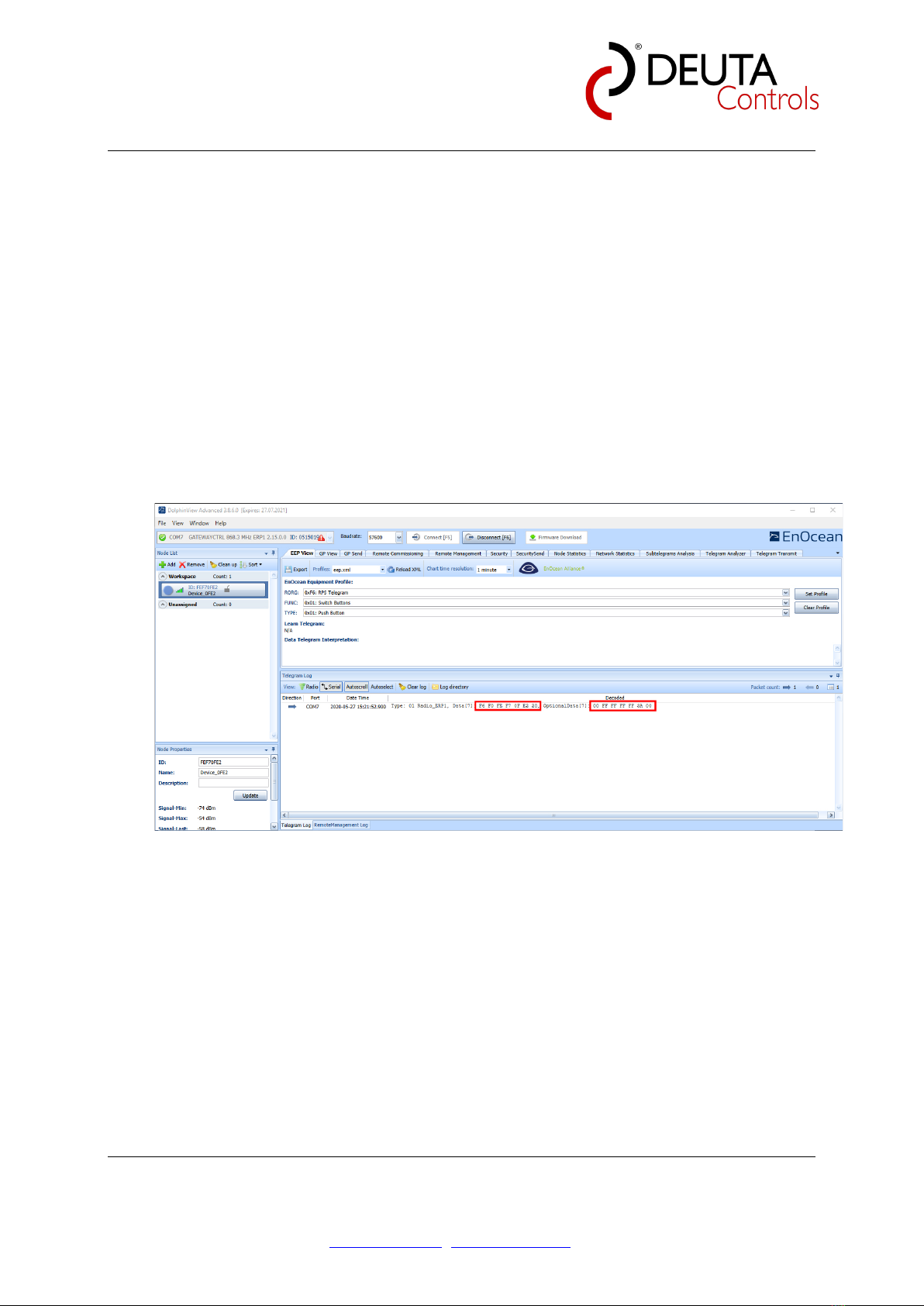
6.1 Receiving and transmitting of EnOcean data, and transfer in ESP3 format
EnOcean data will be received and transmitted by the EnOcean transceiver and an
integrated PCB antenna. Once connected to the EnoDisc via Ethernet TCP on port
8424, data will be sent by / can be received by the EnoDisc®.
Note:
The Ethernet connection will be closed after 10 seconds without any data transfer.
As an example, the following picture shows data received via EnOcean, using the
software tool Dolphin View.
Same data will be transferred by Ethernet.
AL-512-00-902 IP-EnOcean-Bridge PoE V1
Product manual Page 10 of 32
© DEUTA Controls GmbH Paffrather Str. 140, 51465 Bergisch Gladbach Tel.:+49 2202 285 57- 61
14.07.2021 Hauptstraße 76, 32479 Hille Tel: +49 5734 51466 - 0
Technical data might change info@deuta-controls.de; www.deuta-controls.dnet Fax:+49 5734 51466 - 28
7 The EnoDisc®webserver
To support system installation and maintenance, the EnoDisc provides an integrated
Webserver. The available functions are described below.
7.1 “Home” / EnoDisc device info page
On this page, the main properties of the EnoDisc are shown (Read only, can not be
changed):
•Free text / device name
•Serial number / part nr.
•EURID
•BaseID
•Airtime
•HW- and SW-version
•IP address, subnet mask, gateway
•MAC
•Status DALI bus power supply voltage
•Runtime since last reset
•Sensitivity of the EnOcean receiver
7.2 “EnOcean” / EnOcean data monitor
EnOcean data received and send by the EnoDisc can be analyzed by the EnOcean
monitor on this page. For each message, following data are recorded in a new line:

AL-512-00-902 IP-EnOcean-Bridge PoE V1
Product manual Page 11 of 32
© DEUTA Controls GmbH Paffrather Str. 140, 51465 Bergisch Gladbach Tel.:+49 2202 285 57- 61
14.07.2021 Hauptstraße 76, 32479 Hille Tel: +49 5734 51466 - 0
Technical data might change info@deuta-controls.de; www.deuta-controls.dnet Fax:+49 5734 51466 - 28
•Consecutive number of messages in the list
•Direction (receive / transmit)
•EnOcean-ID
•RORG
•Data
•Optional data
•Repeater level
•RSSI [dbm]
•Target address
•Time elapsed since last message
•Time stamp
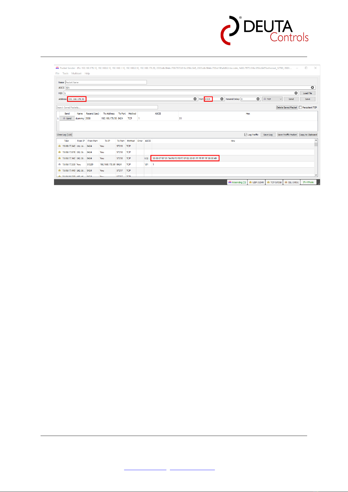
7.3 “Repeater” / EnOcean repeater configuration
The EnoDisc allows to activate an EnOcean repeater (selective) if needed. By default,
the repeater is disabled.
Using the drop-down list, the repeater function can be activated in different modes.
Available options are as follows:
7.3.1 Repeater / Mode
Level 1 Any EnOcean telegram that has not been repeated before will
be repeated / send again by the EnoDisc.
Level 1 OR Filter This mode is a selective repeater mode which allows to define
which kind of message should be repeated by the Level 1
repeater. More than one rule can be defined.
Level 1 AND Filter This mode is a selective repeater mode which allows to define
which kind of message should be repeated by the Level 1
repeater. More than one rule can be defined.
Level 2 Any EnOcean telegram that has not been already repeated by
another level 2 repeater before will be send again by the
EnoDisc.
Level 2 OR Filter This mode is a selective repeater mode which allows to define
which kind of message should be repeated. More than one
rule can be defined.
Level 2 AND Filter This mode is a selective repeater mode which allows to define
which kind of message should be repeated. More than one
rule can be defined.
AL-512-00-902 IP-EnOcean-Bridge PoE V1
Product manual Page 12 of 32
© DEUTA Controls GmbH Paffrather Str. 140, 51465 Bergisch Gladbach Tel.:+49 2202 285 57- 61
14.07.2021 Hauptstraße 76, 32479 Hille Tel: +49 5734 51466 - 0
Technical data might change info@deuta-controls.de; www.deuta-controls.dnet Fax:+49 5734 51466 - 28
Figure 1: Repeater mode selection
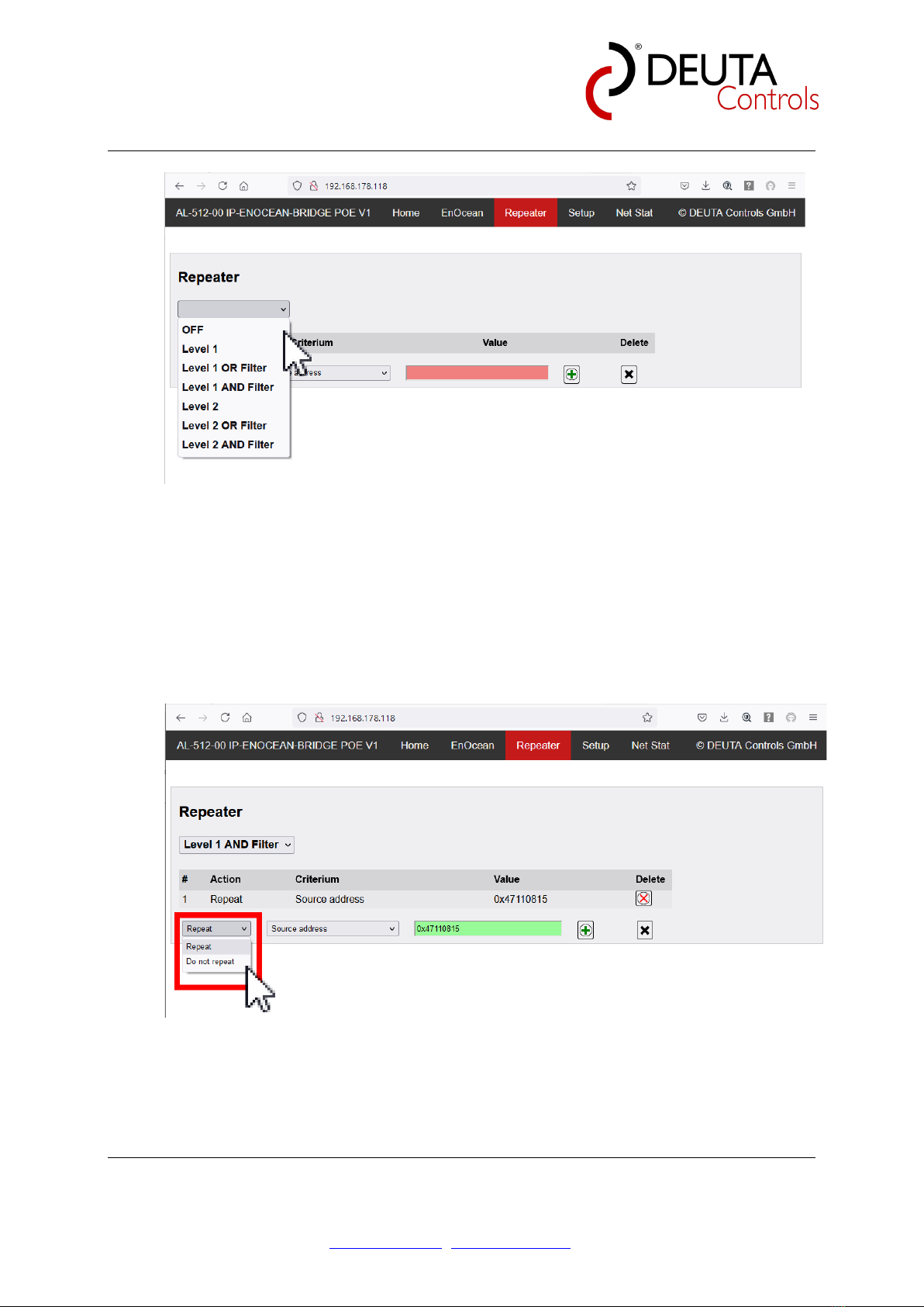
7.3.2 Repeater / Action
If an “OR” or an “AND” filter mode is selected (Level 1 or Level 2), you can define if
the rule will force (“Repeat”) or explicitly avoid (“Do not repeat”) to repeat the selected
telegram type.
Figure 2: Repeater mode selection / Action force or block
AL-512-00-902 IP-EnOcean-Bridge PoE V1
Product manual Page 13 of 32
© DEUTA Controls GmbH Paffrather Str. 140, 51465 Bergisch Gladbach Tel.:+49 2202 285 57- 61
14.07.2021 Hauptstraße 76, 32479 Hille Tel: +49 5734 51466 - 0
Technical data might change info@deuta-controls.de; www.deuta-controls.dnet Fax:+49 5734 51466 - 28
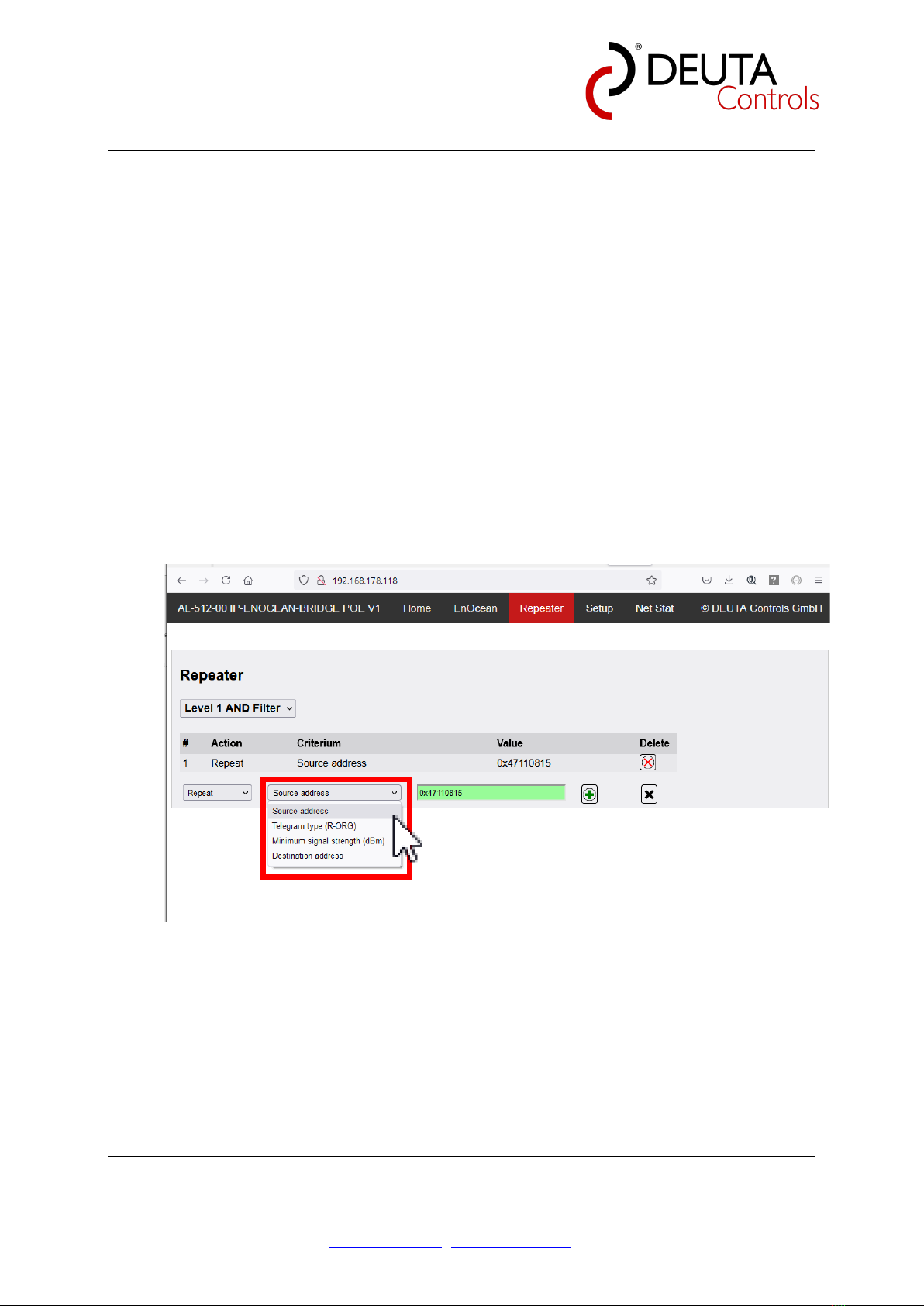
7.3.3 Repeater / Criterium
Any repeater rule can be defined based on the properties of a received EnOcean
message. The possible options are as follows:
Source address Only messages from this source address
(EURID) will be repeated.
Telegram type Only messages of the selected message type
will be repeated.
Minimum signal strength (dBm) Messages must have at least the selected
signal strength to be repeated.
Destination address Only messages with this target address
(EURID) will be repeated.
Figure 3: Repeater / Criterium
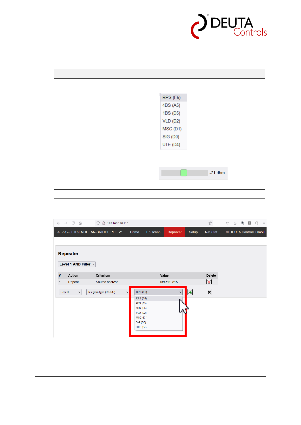
7.3.4 Repeater / Criterium value
Depending on the selected criterium, a value has to be selected / entered:
AL-512-00-902 IP-EnOcean-Bridge PoE V1
Product manual Page 14 of 32
© DEUTA Controls GmbH Paffrather Str. 140, 51465 Bergisch Gladbach Tel.:+49 2202 285 57- 61
14.07.2021 Hauptstraße 76, 32479 Hille Tel: +49 5734 51466 - 0
Technical data might change info@deuta-controls.de; www.deuta-controls.dnet Fax:+49 5734 51466 - 28
Criterium Value
Destination address EURID in HEX (0xnnnnnnnn)
Telegram type
Minimum signal strength (dBm)
-90 .. -50 dBm, selected by the slider
Source address EURID in HEX (0xnnnnnnnn)
Table 10: Repeater criterium
Figure 4: Repeater / Value dropdown for telegram type
AL-512-00-902 IP-EnOcean-Bridge PoE V1
Product manual Page 15 of 32
© DEUTA Controls GmbH Paffrather Str. 140, 51465 Bergisch Gladbach Tel.:+49 2202 285 57- 61
14.07.2021 Hauptstraße 76, 32479 Hille Tel: +49 5734 51466 - 0
Technical data might change info@deuta-controls.de; www.deuta-controls.dnet Fax:+49 5734 51466 - 28
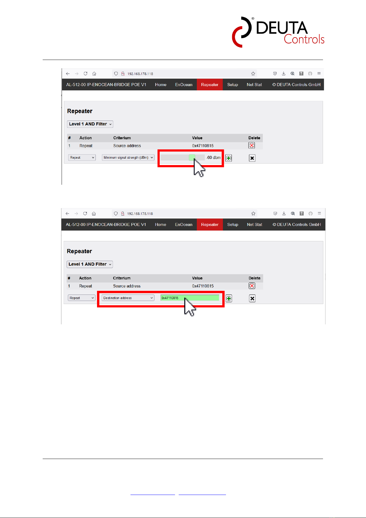
Figure 5: Repeater criterium value signal strength
Figure 6: Repeater criterium value source / destination address
7.3.5 Add or remove rules for the repeater
Using the “+” and “-“ buttons, you can add or remove rules from the list.

AL-512-00-902 IP-EnOcean-Bridge PoE V1
Product manual Page 16 of 32
© DEUTA Controls GmbH Paffrather Str. 140, 51465 Bergisch Gladbach Tel.:+49 2202 285 57- 61
14.07.2021 Hauptstraße 76, 32479 Hille Tel: +49 5734 51466 - 0
Technical data might change info@deuta-controls.de; www.deuta-controls.dnet Fax:+49 5734 51466 - 28
7.4 “Setup” / Ethernet and EnOcean interface properties
7.4.1 Password
The page is password protected, to avoid any unwanted change of the device
parameters. The password is dynamic, and is based on the system time
The password is defined as follows:
System time of the PC = hh:mm
Password to enter = mm:hh
Note: The colon is part of the password and must be entered.
Figure 7: Password protection

AL-512-00-902 IP-EnOcean-Bridge PoE V1
Product manual Page 17 of 32
© DEUTA Controls GmbH Paffrather Str. 140, 51465 Bergisch Gladbach Tel.:+49 2202 285 57- 61
14.07.2021 Hauptstraße 76, 32479 Hille Tel: +49 5734 51466 - 0
Technical data might change info@deuta-controls.de; www.deuta-controls.dnet Fax:+49 5734 51466 - 28
7.4.2 Device properties
On this page, user can edit the following wireless and wired interface parameters:
•Free text / device name
•DHCP or Static IP address
•IP address
•Subnet mask
•Gateway
•Sensitivity of EnOcean receiver: -90 .. -102 dbm (default: -96 dbm)
7.4.2.1 Freetext
To identify the device, a free text can be entered (up to 19 characters).
AL-512-00-902 IP-EnOcean-Bridge PoE V1
Product manual Page 18 of 32
© DEUTA Controls GmbH Paffrather Str. 140, 51465 Bergisch Gladbach Tel.:+49 2202 285 57- 61
14.07.2021 Hauptstraße 76, 32479 Hille Tel: +49 5734 51466 - 0
Technical data might change info@deuta-controls.de; www.deuta-controls.dnet Fax:+49 5734 51466 - 28
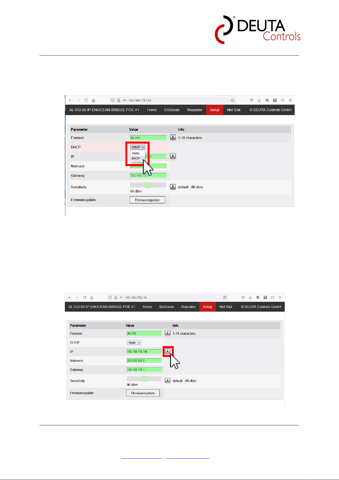
7.4.2.2 DHCP
The EnoDisc®supports DHCP or a static assigned address. Depending on the Drop
down list selection, DHCP mode is activated or not.
Figure 8: Select DHCP or static IP address
7.4.2.3 IP / Netmask / Gateway
When “Static” is selected in the drop down list, the static IP address, netmask and
gateway address can be changed. To store, the according button has to be pressed
once. All three parameters will be changed at the same time.
Figure 9: IP address selection / static or DHCP

AL-512-00-902 IP-EnOcean-Bridge PoE V1
Product manual Page 19 of 32
© DEUTA Controls GmbH Paffrather Str. 140, 51465 Bergisch Gladbach Tel.:+49 2202 285 57- 61
14.07.2021 Hauptstraße 76, 32479 Hille Tel: +49 5734 51466 - 0
Technical data might change info@deuta-controls.de; www.deuta-controls.dnet Fax:+49 5734 51466 - 28
7.4.2.4 EnOcean receiver sensitivity
By default, a sensitivity of -96 dBm has been configured for the EnOcean receiver
as the factory default. This provides the best performance in most of the
applications. Sometimes, it might help to increase / decrease the sensitivity to
optimize a single EnoDisc of a system depending on the surrounding environment
User can finetune the sensitivity in a range from -90 dBm (less sensitive) up to
- 102 dBm (more sensitive).
Use the slider to select the value, and then push the Store button.
Figure 10: Set EnOcean receiver sensitivity
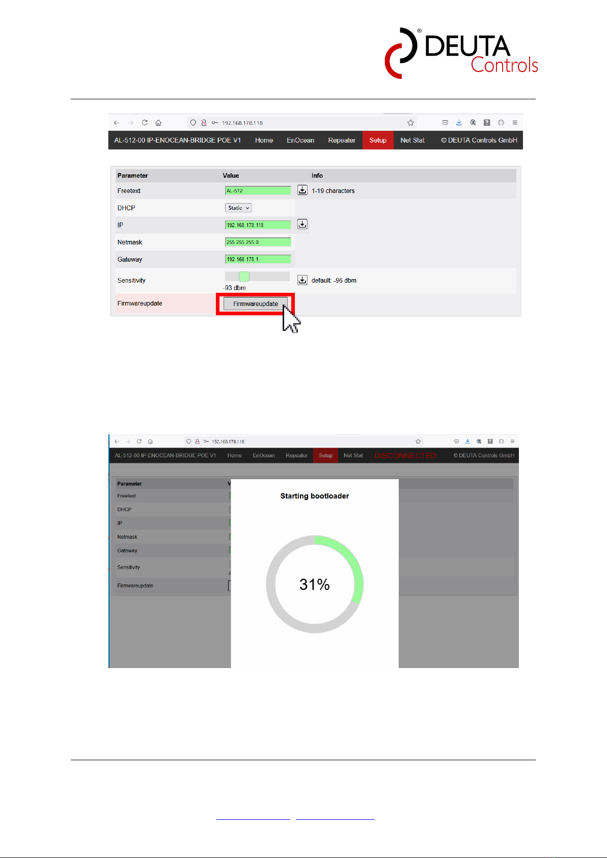
7.4.2.5 EnoDisc Firmware update
Firmware of the device can be updated at any time via Ethernet. Push the button
“Firmwareupdate” to start.
AL-512-00-902 IP-EnOcean-Bridge PoE V1
Product manual Page 20 of 32
© DEUTA Controls GmbH Paffrather Str. 140, 51465 Bergisch Gladbach Tel.:+49 2202 285 57- 61
14.07.2021 Hauptstraße 76, 32479 Hille Tel: +49 5734 51466 - 0
Technical data might change info@deuta-controls.de; www.deuta-controls.dnet Fax:+49 5734 51466 - 28
Figure 11: Start firmware update dialog / enter bootloader
After the button has been pushed, EnoDisc will enter into bootloader mode. Progress
will be shown (0..100%).
Figure 12: EnoDisc entering bootloader mode
When bootloader mode has been started, the page will show the actual properties,
and also the actual firmware version.
This manual suits for next models
1
Table of contents


