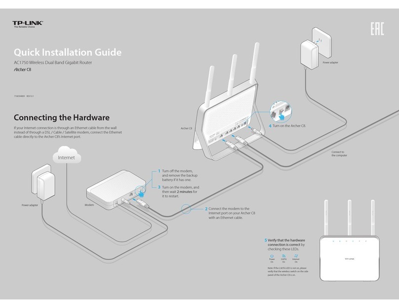
Charles 3641-80 User manual

Telecommunications Group
3641-80 / 3648-80
Ethernet Routers
Guide and Web Users Manual
Section 364-180-N02
Equipment Issue 1
1st Printing, April, 2006
©2006 Charles Industries, Ltd.
All rights reserved. Printed in United States ofAmerica.
The availability of features and technical specifications herein subject to change without notice.

Section 364-180-N02
©2006 Charles Industries, Ltd.
All rights reserved. Printed in United States ofAmerica.
i
Contents
1. About This Manual ..................................................................................................................1
1.1. Revision History........................................................................................................................1
1.2. Document Organization.............................................................................................................1
1.3. Glossary of Terms and Acronyms ............................................................................................. 1
2. General Overview....................................................................................................................3
3. Specifications...........................................................................................................................5
4. Applications.............................................................................................................................7
5. Installation................................................................................................................................9
5.1. Preparing Before Installation..................................................................................................... 9
5.2. Installation Procedures..............................................................................................................9
6. Web Configuration Tool.........................................................................................................11
6.1. About the Web Configuration.................................................................................................. 11
6.2. Factory Default Settings.......................................................................................................... 11
6.3. TCP/IP Configuration..............................................................................................................12
6.4. Login to Web Configuration Tool............................................................................................17
6.5. Status Menu.............................................................................................................................19
6.6. System Menu...........................................................................................................................22
Error Log......................................................................................................................22
Upgrade 23
Restart 25
6.7. Configuration Menu................................................................................................................ 26
Save config...................................................................................................................27
Authentication..............................................................................................................29
LAN Connections ........................................................................................................33
WAN Connections .......................................................................................................36
IP routes 52
DHCP Server................................................................................................................54
DNS Client...................................................................................................................61
The availability of features and technical specifications herein subject to change without notice.

Section 364-180-N02
©2006 Charles Industries, Ltd.
All rights reserved. Printed in United States of America.
ii
DNS Relay...................................................................................................................63
Security 66
VPN Configuration......................................................................................................88
SNTP client................................................................................................................105
Syslog 109
SNMP 110
Port 115
7. CLI Configuration Tool .......................................................................................................117
7.1. Help Text for Using the CLI Commands............................................................................... 118
7.2. Download/Upload Configuration File................................................................................... 119
7.3. Using the source CLI commands ..........................................................................................122
7.4. CLI Application Examples.................................................................................................... 124
Note: After loading the scripts, save the configuration and restart the routerFrame
Relay - bridged...........................................................................................................124
Frame Relay - routed .................................................................................................127
PPP - bridged .............................................................................................................129
PPP - routed ...............................................................................................................132
7.5. CLI Commands Group..........................................................................................................135
7.6. List of CLI Commands..........................................................................................................136
Appendix: System Limit..............................................................................................................152
The availability of features and technical specifications herein subject to change without notice.

Section 364-180-N02
©2006 Charles Industries, Ltd.
All rights reserved. Printed in United States of America.
iii
List of Figures
Figure 4-1 Router card point to point application....................................................................................7
Figure 4-2 Router card frame relay application.......................................................................................7
Figure 4-3 Router card VPN application .................................................................................................8
Figure 4-4 Router card dual gateway application....................................................................................8
Figure 6-1 Login Web Configuration Tool.............................................................................................17
Figure 6-2 Web Tool - Welcome page....................................................................................................18
Figure 6-3 Web Tool – Status page........................................................................................................ 20
Figure 6-4 Web Tool – Error Log page..................................................................................................22
Figure 6-5 Web Tool – Firmware Upgrade page....................................................................................23
Figure 6-6 Web Tool – Firmware Upgrade Complete page...................................................................24
Figure 6-7 Web Tool – Reset Router page.............................................................................................25
Figure 6-8 Web Tool – Save configuration Confirm page.....................................................................27
Figure 6-9 Web Tool – Save configuration completed page..................................................................28
Figure 6-10 Web Tool – Authentication page ........................................................................................29
Figure 6-11 Web Tool –Authentication: edit user details page .............................................................30
Figure 6-12 Web Tool –Authentication: create user page.....................................................................31
Figure 6-13 Web Tool –Authentication: Currently Defined Users page...............................................32
Figure 6-14 Web Tool – LAN connection page.....................................................................................33
Figure 6-15 Web Tool – WAN connections page...................................................................................36
Figure 6-16 Web Tool – WAN connection: create service page ............................................................36
Figure 6-17 Web Tool - WAN connection: Frame Relay routed page ...................................................38
Figure 6-18 Web Tool – WAN connection: frame relay routed: Edit Service page...............................39
Figure 6-19 Web Tool – WAN connection: Edit Frame Relay channel page.........................................40
Figure 6-20 Web Tool – WAN connection: Edit IP Interface page........................................................ 41
Figure 6-21 Web Tool – WAN connection: Edit Rip Versions page......................................................42
Figure 6-22 Web Tool – WAN connection: Frame Relay bridged page.................................................43
Figure 6-23 Web Tool – WAN connections page...................................................................................44
The availability of features and technical specifications herein subject to change without notice.

Section 364-180-N02
©2006 Charles Industries, Ltd.
All rights reserved. Printed in United States of America.
iv
Figure 6-24 Web Tool – WAN connection: PPP routed page.................................................................46
Figure 6-25 Web Tool – WAN connections page...................................................................................47
Figure 6-26 Web Tool – WAN connection: PPP bridged page...............................................................50
Figure 6-27 Web Tool – WAN connections page...................................................................................51
Figure 6-28 Web Tool – WAN connection: delete ‘Frame Relay routed’page......................................52
Figure 6-29 Web Tool – IP routes: Create Ip V4Route page..................................................................53
Figure 6-30 Web Tool – IP routes: Edit Routes page.............................................................................53
Figure 6-31 Web Tool – DHCP server page...........................................................................................54
Figure 6-32 Web Tool – DHCP: enable server page..............................................................................56
Figure 6-33 Web Tool – DHCP: enable relay agent page......................................................................59
Figure 6-34 Web Tool – DHCP server: DHCP relay enabled page........................................................60
Figure 6-35 Web Tool – DNS Client page.............................................................................................61
Figure 6-36 Web Tool – DNS Client page.............................................................................................62
Figure 6-37 Web Tool – DNS relay page...............................................................................................63
Figure 6-38 Web Tool – DNS: enable relay page ..................................................................................64
Figure 6-39 Web Tool – DNS relay enabled page..................................................................................65
Figure 6-40 Web Tool – Security page...................................................................................................66
Figure 6-41 Web Tool – Security: Security Interfaces page ..................................................................67
Figure 6-42 Web Tool – Security: Security Interfaces page ..................................................................68
Figure 6-43 Web Tool – Security: Advanced NAT Configuration page ................................................69
Figure 6-44 Web Tool – Security: Firewall Add Global Address Pool page..........................................69
Figure 6-45 Web Tool – Security: Advanced NAT Configuration page ................................................70
Figure 6-46 Web Tool – Security: Firewall Delete Global Address Pool page...................................... 71
Figure 6-47 Web Tool – Security: Security Interfaces page ..................................................................72
Figure 6-48 Web Tool – Security: Add Reserved Mappings page.........................................................72
Figure 6-49 Web Tool – Security: Firewall Add Reserved Mapping page ............................................73
Figure 6-50 Web Tool - Security: Reserved Mappings page .................................................................74
Figure 6-51 Web Tool – Security: Firewall Delete Reserved Mappings page.......................................74
Figure 6-52 Web Tool – Security: Firewall Policy Configuration page................................................. 75
The availability of features and technical specifications herein subject to change without notice.

Section 364-180-N02
©2006 Charles Industries, Ltd.
All rights reserved. Printed in United States of America.
v
Figure 6-53 Web Tool – Security: FirewallAdd TCP Port Filter page..................................................76
Figure 6-54 Web Tool – Security: FirewallAdd Raw IP Filter page .....................................................77
Figure 6-55 Web Tool – Security: Firewall Add Trigger page...............................................................81
Figure 6-56 Web Tool – Security: Firewall Configuration Intrusion Detection page............................84
Figure 6-57 Web Tool – Security: Alerting Configuration for Intrusion page.......................................86
Figure 6-58 Web Tool – IPSec Configuration page ...............................................................................93
Figure 6-59 Web Tool – IPSec: Create New IPSec Endpoint page........................................................94
Figure 6-60 Web Tool – IPSec: User Certificates page..........................................................................98
Figure 6-61 Web Tool – IPSec: Generate Certificate Request page ......................................................99
Figure 6-62 Web Tool – IPSec:Add new CA certificate page.............................................................100
Figure 6-63 Web Tool – PPTP Configuration page..............................................................................102
Figure 6-64 Web Tool – PPTP:Authentication: create user page........................................................102
Figure 6-65 Web Tool – SNTP client page ..........................................................................................105
Figure 6-66 Web Tool – SNTP client: SNTP Synchronization Mode page .........................................105
Figure 6-67 Web Tool – SNTP client: Enter Unicast Server IP Address page.....................................107
Figure 6-68 Web Tool – SNTP client: SNTP Client General Configuration Parameters page ............108
Figure 6-69 Web Tool – SNTP client: ISOS Clock Setting page.........................................................109
Figure 6-70 Web Tool – Syslog Client Configuration page................................................................. 109
Figure 6-71 Web Tool – Snmp page..................................................................................................... 111
Figure 6-72 Web Tool – Snmp: select Action page.............................................................................. 112
Figure 6-73 Web Tool – Snmp: Snmp Show Community page........................................................... 112
Figure 6-74 Web Tool – Snmp: Snmp Add Community page ............................................................. 113
Figure 6-75 Web Tool – Snmp: Snmp Add Host page......................................................................... 113
Figure 6-76 Web Tool – Snmp: Snmp Add Trap page......................................................................... 114
Figure 6-77 Web Tool – Snmp: Snmp Show Host page....................................................................... 114
Figure 6-78 Web Tool – Snmp: Snmp Show Trap page....................................................................... 114
Figure 6-79 Web Tool – Ports: Ethernet Port Configuration page....................................................... 115
Figure 6-80 Web Tool – Ports:Advanced Ethernet Port Configuration page...................................... 116
Figure 7-1 Login CLI Configuration Tool........................................................................................... 117
The availability of features and technical specifications herein subject to change without notice.

Section 364-180-N02
©2006 Charles Industries, Ltd.
All rights reserved. Printed in United States of America.
vi
The availability of features and technical specifications herein subject to change without notice.

Section 364-180-N02
©2006 Charles Industries, Ltd.
All rights reserved. Printed in United States of America.
vii
List of Tables
Table 1-1 Revision history table ..............................................................................................................1
Table 1-2 Glossary of terms and acronyms..............................................................................................1
Table 3-1 Router card specifications........................................................................................................ 5
Table 6-1 Default user name and password...........................................................................................29
Table 6-2 User access levels ..................................................................................................................31
Table 6-3 Syslog severity levels........................................................................................................... 110
Table 7-1 Default names of different Interface/Transport/Port............................................................124
Table 7-2 List of CLI commands.........................................................................................................136
The availability of features and technical specifications herein subject to change without notice.

Issue 1.0, April 2006 Section 364-180-N02
©2006 Charles Industries, Ltd.
All rights reserved. Printed in United States of America.
1
1. About This Manual
1.1. Revision History
Table 1-1 Revision history table
Revision Date Description
Issue 1.0 April, 2006 Initial release
1.2. Document Organization
About This Manual,Chapter 1, introduces you to the document.
General Overview, Chapter 2, provides overview and features of the router card.
Specification,Chapter 3, provides the technical specifications.
Applications, Chapter 4, introduces some application examples.
Installation, Chapter 5, provides the installation procedures.
Controls and Indicators, Chapter 6, provides the descriptions of controls and LED activity.
Web Configuration Tool, Chapter 7, provides the details of the web configuration.
CLI Configuration Tool, Chapter 8, introduces the CLI configuration and provides some setting
examples.
1.3. Glossary of Terms and Acronyms
Table 1-2 Glossary of terms and acronyms
Abbreviations Description
CHAP Challenge-Handshake Authentication Protocol
CLI Command Line Interface
DCE Data Communication Equipment
DHCP Dynamic Host Configuration Protocol
DTE Data Terminal Equipment
DNS Domain Name System
IGMP Internet Group Management Protocol
IP Internet Protocol
IPSec IP Security Protocol
LAN Local Area Network
The availability of features and technical specifications herein subject to change without notice.

Issue 1.0, April 2006 Section 364-180-N02
©2006 Charles Industries, Ltd.
All rights reserved. Printed in United States of America.
2
L2TP Layer Two Tunneling Protocol
NAT Network Address Translation
PAP Password Authentication Procedure
PPP Point to Point Protocol
PPPoH PPP over High-Level Data Link Control
PPTP Point to Point Tunneling Protocol
PVC Permanent Virtual Circuit
RIP Routing Information Protocol
SNTP Simple Network Time Protocol
SNMP Simple Network Management Protocol
VPN Virtual Private Networking
WAN Wide Area Network
The availability of features and technical specifications herein subject to change without notice.

Issue 1.0, April 2006 Section 364-180-N02
©2006 Charles Industries, Ltd.
All rights reserved. Printed in United States of America.
3
2. General Overview
This document supports both the 3641-80 Single Port router and the 3648-80 router which
includes an 8 port Ethernet switch. The router cards are Ethernet IP routers, which mounts in a
full size card slot. The only difference between the 3641-80 and 3648-80 is that the 3648-80 has
an unmanaged Ethernet switch to eliminate the need for an external switch. Therefore the routers
will be referred to as ‘the router’. The router includes an Ethernet interface to provide data
services from the T1/E1 interface. The router can act as a frame relay router, frame relay bridge,
firewall, VPN gateway, or IP sharing.
For purposes of understanding, the Ethernet port represents the LAN side of the router and the
T1/E1 represents the WAN side of the router.
The router card provides three primary services:
1. Provides a standard T1/E1 gateway function between the customer Ethernet interface and
the WAN data service channel on the T1/E1 interface.
2. Provides the possibility for including voice and data over the same T1/E1 line.
3. Provides a flexible programmable data rate 56/64K x N bps where N = 1…24 for T1, 1…30
for E1 (i.e. 56K ~ 1.536M bps for T1, 56K ~ 1.92M bps for E1).
Equipment Features
Provide one Ethernet port with 10/100 BaseT auto sensing (3641-80)
Provide Eight Ethernet ports with 10/100 BaseT auto sensing and auto crossover cable
sensing (3648-80 only)
Provide one female RS-232 DCE console port (also referred to as a craft port) for set up
and management
Provide management via CLI (by console port or Telnet) and web browser
Support SNMP V1/V2c management (maximum 10 SNMP managers and trap recipients
are allowed at any one time when using the router Ethernet port)
Support RIP V1 and V2
Support NAT and NAPT
The availability of features and technical specifications herein subject to change without notice.

Issue 1.0, April 2006 Section 364-180-N02
©2006 Charles Industries, Ltd.
All rights reserved. Printed in United States of America.
4
Support DHCP Server / Relay Agent / Client mode
Support DNS Client / Relay mode
Support Frame Relay WAN layer 2 protocol
Support PAP and CHAP
Support all three types of VPN --- IPSec, PPTP, and L2TP
Simple firmware update via web-based GUI interface
NOTE: There are certain features that are only accessible through the Web Configuration Tool:
1. Digital signature certificates of IPSec
2. Remote upgrade firmware (by browser http-upload.tar file)
3. Errorlog
There are certain features that are only accessible through the CLI Configuration Tool:
1. Webserver configuration
2. DHCP client parameters configuration (such as reboot time, retry time, backoff time, etc.)
3. Upload/download the configuration file to/from system/PC
4. Local upgrade firmware (via tftp/bootp protocol)
5. Set rip host route and set rip poison
The availability of features and technical specifications herein subject to change without notice.

Issue 1.0, April 2006 Section 364-180-N02
©2006 Charles Industries, Ltd.
All rights reserved. Printed in United States of America.
5
3. Specifications
Table 3-1 Router card specifications
Parameter Specification
Dimension:
Height
Width
Depth
1.9 cm
24.45 cm
23.49 cm
Weight
300 g
Operating Environment (in service) -40℃~ +65℃<95﹪RH
Power:
Less than 1 amp.
DC input voltage range of – 42V to 56V
Console por
t
Standard DB-9 connector, DCE configured with
baud rate 9600, 8 bits of data, no parity, and 1 stop
bit
Ethernet port RJ-45 connector with IEEE 802.3 compatible,
10/100BaseT auto sensing (both 3641-80 and
3648-80), and auto crossover cable sensing (3648-80
only)
WAN side data rate: 56K to 1.536 M b/s
IP Protocol Support:
TCP
UDP
ICMP
Meet the requirements of RFC 793
Meet the requirements of RFC 768
Meet the requirements of RFC 792/STD 0005
updated with RFC 950/STD 0005.
The availability of features and technical specifications herein subject to change without notice.

Issue 1.0, April 2006 Section 364-180-N02
©2006 Charles Industries, Ltd.
All rights reserved. Printed in United States of America.
6
Meet the requirements of RFC 1058 and RFC 2453.
Meet the requirements of RFC 2236.
Supports IGMP Proxy as described in
[draft-ietf-idmr-igmp-proxy-03] “IGMP-based
Multicast Forwarding (IGMP Proxying)”, W. Fenner,
July 2000.
Meet the requirements of RFC 3442 and the current
practice defined in RFC 3180/BGP 0053.
Meet the Best Current Practice defined in RFC
3180/BGP 0053 and the requirements defined in
RFC 1517, RFC 1518 and RFC 1519.
Meet the requirements of RFC 826/STD 0037.
RIPV1andV2
IGMP
Static routing
CIDR
ARP
DHCP Meet the requirements of RFC 3022 and 3235.
PPP Support:
IPCP
BCP
LCP
L2TP
PPTP
Meet the PPP IPCP RFC 1332.
Meet the requirements of IEEE 802.1D MAC
Bridging and RFC 1638.
Meet the requirements of RFC 1570.
Meet the requirements of RFC 3070 and 3438.
Meet the requirements of RFC 1661/STD0051.
Frame Relay:
The system serves as end stations (DTEs) on a
public or private Frame Relay network.
Meet the requirements of RFC 2427/STD 0055.
Security Support:
PAP and CHAP
Meet the current practice defined in RFC1334 for
PAP and RFC 1994 for CHAP.
The availability of features and technical specifications herein subject to change without notice.

Issue 1.0, April 2006 Section 364-180-N02
©2006 Charles Industries, Ltd.
All rights reserved. Printed in United States of America.
7
4. Applications
The router card can act as a frame relay router, frame relay bridge, firewall, VPN gateway, or IP
sharing. The following figures are application examples.
Point-to-Point application
Figure 4-1 is for either router or bridge applications.
ICB 360
T1/E1 Point-to-Point T1/E1
ICB 360
10/100BaseT 10/100BaseT
PBX
TDM Voice
PBX
TDM Voice
LAN LAN
Figure 4-1 Router card point to point application
Frame Relay application
I CB 360
T1/E1
Fr ame Rel ay
T1/E1
I CB 360
LAN
10/100BaseT
LAN
10/100BaseT
Figure 4-2 Router card frame relay application
VPN application
ICB 360
T1/E1
Internet
ICB 360
10/100BaseT
FTP Ser v er
Web Ser v er
Swi t c h/ H ub
Swi t ch/ Hub
Laptop
Ser v er
Office
Di al -up
Connecti on
Broadband
Modem Laptop
Remote Si te
Main Office
Mobile User
The availability of features and technical specifications herein subject to change without notice.

Issue 1.0, April 2006 Section 364-180-N02
©2006 Charles Industries, Ltd.
All rights reserved. Printed in United States of America.
8
Figure 4-3 Router card VPN application
Dual Gateway application
ICB 360
Secondar y
T1/E1
Fr ame Rel ay
T1/E1
ICB 360
LAN
10/100BaseT
LAN
10/100BaseT
Pr i mar y
T1/E1
Fr ame Rel ay
LAN
10/100BaseT
T1/E1
ICB 360
Figure 4-4 Router card dual gateway application
The availability of features and technical specifications herein subject to change without notice.

Issue 1.0, April 2006 Section 364-180-N02
©2006 Charles Industries, Ltd.
All rights reserved. Printed in United States of America.
9
5. Installation
5.1. Preparing Before Installation
The major functions of the Router Card are performed by the Ethernet network interface. Your
computer must have an Ethernet Network Interface Card (NIC) installed and set up with the
TCP/IP protocol before beginning to use the router. The router also provides a serial console port
for monitoring and configuring the router via the built-in command line interface.
You will need to know the Internet Protocol supported by your T1/E1 provider to successfully
connect to the Internet. For future troubleshooting or reinstallation, it is important that you retain
these details.
Before beginning the hardware installation, please gather the following materials for the setup.
At least one computer running a supported *operating system, with an Ethernet Network
Interface Card (NIC) installed (or more computers if you use an external hub).
TCP/IP protocol installed for each NIC.
Ethernet straight connect cable (one for each computer you will be connecting)
RS-232 serial cable (Optional)
* The router Web Configuration tool supports browsers that operate under Windows 95, 98,
2000, XP and Unix system. Configuration can also be done via telnet, ftp or through an
RS-232 RTR MGMT port.
5.2. Installation Procedures
To install the router card, follow the procedure in the router practice (LT364-180-202) or the
router installation guide (LT364-180-802).
The availability of features and technical specifications herein subject to change without notice.


Issue 1.0, April 2006 Section 364-180-N02
©2006 Charles Industries, Ltd.
All rights reserved. Printed in United States of America.
11
6. Web Configuration Tool
6.1. About the Web Configuration
The Web Configuration tool provides a series of web pages that you can use to setup and
configure your Router card. There are three main menus. You can select each of the following
menus from the left frame of the main window:
Status Menu: Information about the current setup and status of the system and system
hardware and options..
System Menu: Information about the error log, upgrading the firmware and restarting the
system.
Configuration Menu: Information about the current configuration of various system features
with options to change the configuration.
NOTE: There are certain features that are only accessible through the Web
Configuration Tool:
1. Digital signature certificates of IPSec
2. Remote upgrade firmware (by browser http-upload.tar file)
3. Errorlog
6.2. Factory Default Settings
If your required configuration exactly matches the settings below, the router will work for you as
pre-configured. After completing the installation, assigning your static IP address to your
computer’s TCP/IP settings, you should be able to make a connection to the Internet.
LAN Port: IP Address: 192.168.0.1
Subnet Mask: 255.255.255.0
DHCP Server: Disabled
Loopback: IP Address: 127.0.0.1
The availability of features and technical specifications herein subject to change without notice.

Issue 1.0, April 2006 Section 364-180-N02
©2006 Charles Industries, Ltd.
All rights reserved. Printed in United States of America.
12
6.3. TCP/IP Configuration
In order to access the router’s Web GUI to begin your configuration, you must have the TCP/IP
protocol installed and configured properly in your computer’s network interface card. Your
computer’s TCP/IP settings must allow your computer to obtain an IP address automatically.
To connect to the Internet or configure the router via Ethernet, the TCP/IP protocol must be
installed and configured correctly. Follow the steps below to determine if you have TCP/IP
installed and configured correctly for Windows 95/98.
Step 1 - Check if TCP/IPis installed
1. From your computer’s desktop, double-click
on My Computer, then Control Panel, and
then double-click the Network icon.
2. In the “Network” window, choose the
Configuration tab. Check that TCP/IP is
installed and setup for the Ethernet NIC that
is installed in your computer. If you see, for
example, TCP/IP->Intel 21140 based 10/
100mbps Ethernet Controller, that means
that TCP/IP has been installed.
• If TCP/IP has not been installed for your NIC, proceed to Step 2 as below.
OR –
The availability of features and technical specifications herein subject to change without notice.
Other manuals for 3641-80
1
This manual suits for next models
1
Table of contents
Other Charles Network Router manuals
Popular Network Router manuals by other brands
Atlantis Land
Atlantis Land Edge-Core A07-ES5508 Specification sheet
Linksys
Linksys HomeLink HPB200 user guide

Cambium Networks
Cambium Networks PTP 670 Series quick start guide
SMC Networks
SMC Networks SMC Barricade Plus SMC7004WFW user guide
Amer.com
Amer.com SS2R24G4i user manual
Mercusys
Mercusys MW305R Quick installation guide

