Blueweld BESTPLASMA 70 User manual

- 1 -
Cod.954514
(EN) EXPLANATION OF DANGER, MANDATORY AND
PROHIBITION SIGNS.
(IT) LEGENDA SEGNALI DI PERICOLO, D’OBBLIGO E DIVIETO.
(FR) LÉGENDE SIGNAUX DE DANGER, D’OBLIGATION ET
D’INTERDICTION.
(ES) LEYENDA SEÑALES DE PELIGRO, DE OBLIGACIÓNY
PROHIBICIÓN.
(DE) LEGENDE DER GEFAHREN-, GEBOTS- UND
VERBOTSZEICHEN.
(RU) ЛЕГЕНДА СИМВОЛОВ БЕЗОПАСНОСТИ, ОБЯЗАННОСТИ
И ЗАПРЕТА.
(PT) LEGENDA DOS SINAIS DE PERIGO, OBRIGAÇÃO E
PROIBIDO.
(EL) ΛΕΖΑΝΤΑ ΣΗΜΑΤΩΝ ΚΙΝΔΥΝΟΥ, ΥΠΟΧΡΕΩΣΗΣ ΚΑΙ
ΑΠΑΓΟΡΕΥΣΗΣ.
(NL) LEGENDE SIGNALEN VAN GEVAAR,VERPLICHTING EN
VERBOD.
(HU) A VESZÉLY, KÖTELEZETTSÉG ÉS TILTÁS JELZÉSEINEK
FELIRATAI.
(RO) LEGENDĂ INDICATOARE DE AVERTIZARE A PERICOLELOR,
DE OBLIGARE ŞI DE INTERZICERE.
(SV) BILDTEXT SYMBOLER FÖR FARA, PÅBUD OCH FÖRBUD.
(DA) OVERSIGT OVER FARE, PLIGT OG FORBUDSSIGNALER.
(NO) SIGNALERINGSTEKST FOR FARE, FORPLIKTELSER OG
FORBUDT.
(FI) VAROITUS,VELVOITUS, JA KIELTOMERKIT.
(CS) VYSVĚTLIVKY K SIGNÁLŮM NEBEZPEČÍ, PŘÍKAZŮM A
ZÁKAZŮM.
(SK) VYSVETLIVKY K SIGNÁLOM NEBEZPEČENSTVA, PRÍKAZOM
A ZÁKAZOM.
(SL) LEGENDA SIGNALOV ZA NEVARNOST, ZA PREDPISANO IN
PREPOVEDANO.
(HR-SR) LEGENDA OZNAKA OPASNOSTI, OBAVEZA I ZABRANA.
(LT) PAVOJAUS, PRIVALOMŲJŲ IR DRAUDŽIAMŲJŲ ŽENKLŲ
PAAIŠKINIMAS.
(ET) OHUD, KOHUSTUSED JA KEELUD.
(LV) BĪSTAMĪBU, PIENĀKUMU UN AIZLIEGUMA ZĪMJU
PASKAIDROJUMI.
(BG) ЛЕГЕНДА НА ЗНАЦИТЕ ЗА ОПАСНОСТ, ЗАДЪЛЖИТЕЛНИ
И ЗА ЗАБРАНА.
(PL) OBJAŚNIENIA ZNAKÓW OSTRZEGAWCZYCH, NAKAZU I
ZAKAZU.
(AR) .
(EN) DANGER OF ELECTRIC SHOCK - (IT) PERICOLO SHOCK ELETTRICO - (FR) RISQUE DE CHOC ÉLECTRIQUE - (ES) PELIGRO
DESCARGA ELÉCTRICA - (DE) STROMSCHLAGGEFAHR - (RU) ОПАСНОСТЬ ПОРАЖЕНИЯ ЭЛЕКТРИЧЕСКИМ ТОКОМ - (PT)
PERIGO DE CHOQUE ELÉTRICO - (EL) ΚΙΝΔΥΝΟΣ ΗΛΕΚΤΡΟΠΛΗΞΙΑΣ - (NL) GEVAAR ELEKTROSHOCK - (HU) ÁRAMÜTÉS
VESZÉLYE - (RO) PERICOL DE ELECTROCUTARE - (SV) FARA FÖR ELEKTRISK STÖT - (DA) FARE FOR ELEKTRISK STØD -
(NO) FARE FOR ELEKTRISK STØT - (FI) SÄHKÖISKUN VAARA - (CS) NEBEZPEČÍ ZÁSAHU ELEKTRICKÝM PROUDEM - (SK)
NEBEZPEČENSTVO ZÁSAHU ELEKTRICKÝM PRÚDOM - (SL) NEVARNOST ELEKTRIČNEGA UDARA - (HR-SR) OPASNOST
STRUJNOG UDARA - (LT) ELEKTROS SMŪGIO PAVOJUS - (ET) ELEKTRILÖÖGIOHT - (LV) ELEKTROŠOKA BĪSTAMĪBA -
(BG) ОПАСНОСТ ОТ ТОКОВ УДАР - (PL) NIEBEZPIECZEŃSTWO SZOKU ELEKTRYCZNEGO - (AR)
(EN) DANGER OF FUMES FROM PLASMA CUTTING - (IT) PERICOLO FUMI DI LAVORAZIONE - (FR) DANGER FUMÉES DE
PROCESSUS - (ES) PELIGRO HUMOS DE ELABORACIÓN - (DE) BEIM ARBEITEN GEFAHR DURCH RAUCHGASE - (RU) ОПАСНОСТЬ
ВЫДЕЛЕНИЯ ДЫМОВЫХ ГАЗОВ - (PT) PERIGO DE FUMOS DE PROCESSAMENTO - (EL) ΚΙΝΔΥΝΟΣ ΚΑΠΝΩΝ ΚΑΤΕΡΓΑΣΙΑΣ
- (NL) GEVAAR ROOK VAN BEWERKING - (HU) MUNKAVÉGZÉS KÖVETKEZTÉBEN KELETKEZETT FÜST VESZÉLYE - (RO)
PERICOL GAZE DE SUDURĂ - (SV) FARA FÖR RÖK FRÅN BEARBETNING - (DA) FARE PGA. DAMPE FRA BEARBEJDNINGEN
- (NO) RISIKO FOR RØYK UNDER BEARBEIDELSEN - (FI) TYÖSKENTELYSTÄ AIHEUTUVAN SAVUN VAARA - (CS) NEBEZPEČÍ
DÝMŮ POCHÁZEJÍCÍCH Z PRACOVNÍ ČINNOSTI - (SK) NEBEZPEČENSTVO DYMOV VZNIKAJÚCICH PRI PRACOVNEJ ČINNOSTI
- (SL) NEVARNOST NASTAJANJA DIMNIH HLAPOV MED DELOM - (HR-SR) OPASNOST OD DIMA TIJEKOM RADA - (LT) DŪMŲ
PAVOJUS DARBO METU - (ET) KEEVITAMISEL SUITSU OHT - (LV) IZTVAIKOJUMU BĪSTAMĪBA APSTRĀDES LAIKĀ - (BG)
ОПАСНОСТ ОТ ПУШЕЦИ ПРИ ОБРАБОТВАНЕТО - (PL) NIEBEZPIECZEŃSTWO POWSTAWANIA OPARÓW
- (AR)
(EN) DANGER OF EXPLOSION - (IT) PERICOLO ESPLOSIONE - (FR) RISQUE D’EXPLOSION - (ES) PELIGRO EXPLOSIÓN - (DE)
EXPLOSIONSGEFAHR - (RU) ОПАСНОСТЬ ВЗРЫВА - (PT) PERIGO DE EXPLOSÃO - (EL) ΚΙΝΔΥΝΟΣ ΕΚΡΗΞΗΣ - (NL) GEVAAR
ONTPLOFFING - (HU) ROBBANÁS VESZÉLYE - (RO) PERICOL DE EXPLOZIE - (SV) FARA FÖR EXPLOSION - (DA) SPRÆNGFARE
- (NO) FARE FOR EKSPLOSJON - (FI) RÄJÄHDYSVAARA - (CS) NEBEZPEČÍ VÝBUCHU - (SK) NEBEZPEČENSTVO VÝBUCHU
- (SL) NEVARNOST EKSPLOZIJE - (HR-SR) OPASNOST OD EKSPLOZIJE - (LT) SPROGIMO PAVOJUS - (ET) PLAHVATUSOHT -
(LV) SPRĀDZIENBĪSTAMĪBA - (BG) ОПАСНОСТ ОТ ЕКСПЛОЗИЯ - (PL) NIEBEZPIECZEŃSTWO WYBUCHU - (AR)
(EN) WEARING PROTECTIVE CLOTHING IS COMPULSORY - (IT) OBBLIGO INDOSSARE INDUMENTI PROTETTIVI - (FR) PORT
DES VÊTEMENTS DE PROTECTION OBLIGATOIRE - (ES) OBLIGACIÓN DE LLEVAR ROPA DE PROTECCIÓN - (DE) DAS TRAGEN
VON SCHUTZKLEIDUNG IST PFLICHT - (RU) ОБЯЗАННОСТЬ НАДЕВАТЬ ЗАЩИТНУЮ ОДЕЖДУ - (PT) OBRIGATÓRIO
O USO DE VESTUÁRIO DE PROTEÇÃO - (EL) ΥΠΟΧΡΕΩΣΗ ΝΑ ΦΟΡΑΤΕ ΠΡΟΣΤΑΤΕΥΤΙΚΑ ΕΝΔΥΜΑΤΑ - (NL) VERPLICHT
BESCHERMENDE KLEDIJ TE DRAGEN - (HU) VÉDŐRUHA HASZNÁLATA KÖTELEZŐ - (RO) FOLOSIREA ÎMBRĂCĂMINTEI DE
PROTECŢIE OBLIGATORIE - (SV) OBLIGATORISKT ATT BÄRA SKYDDSPLAGG - (DA) PLIGT TIL AT ANVENDE BESKYTTELSESTØJ
- (NO) FORPLIKTELSE Å BRUKE VERNETØY - (FI) SUOJAVAATETUKSEN KÄYTTÖ PAKOLLISTA - (CS) POVINNÉ POUŽITÍ
OCHRANNÝCH PROSTŘEDKŮ - (SK) POVINNÉ POUŽITIE OCHRANNÝCH PROSTRIEDKOV - (SL) OBVEZNO OBLECITE
ZAŠČITNA OBLAČILA - (HR-SR) OBAVEZNO KORIŠTENJE ZAŠTITNE ODJEĆE - (LT) PRIVALOMA DĖVĖTI APSAUGINĘ
APRANGĄ - (ET) KOHUSTUSLIK KANDA KAITSERIIETUST - (LV) PIENĀKUMS ĢĒRBT AIZSARGTĒRPUS - (BG) ЗАДЪЛЖИТЕЛНО
НОСЕНЕ НА ПРЕДПАЗНО ОБЛЕКЛО - (PL) NAKAZ NOSZENIA ODZIEŻY OCHRONNEJ - (AR)
(EN) WEARING PROTECTIVE GLOVES IS COMPULSORY - (IT) OBBLIGO INDOSSARE GUANTI PROTETTIVI - (FR) PORT DES
GANTS DE PROTECTION OBLIGATOIRE - (ES) OBLIGACIÓN DE LLEVAR GUANTES DE PROTECCIÓN - (DE) DAS TRAGEN VON
SCHUTZHANDSCHUHEN IST PFLICHT - (RU) ОБЯЗАННОСТЬ НАДЕВАТЬ ЗАЩИТНЫЕ ПЕРЧАТКИ - (PT) OBRIGATÓRIO O
USO DE LUVAS DE SEGURANÇA - (EL) ΥΠΟΧΡΕΩΣΗ ΝΑ ΦΟΡΑΤΕ ΠΡΟΣΤΑΤΕΥΤΙΚΑ ΓΑΝΤΙΑ - (NL) VERPLICHT BESCHERMENDE
HANDSCHOENEN TE DRAGEN - (HU) VÉDŐKESZTYŰ HASZNÁLATA KÖTELEZŐ - (RO) FOLOSIREA MĂNUŞILOR DE PROTECŢIE
OBLIGATORIE - (SV) OBLIGATORISKT ATT BÄRA SKYDDSHANDSKAR - (DA) PLIGT TIL AT BRUGE BESKYTTELSESHANDSKER
- (NO) FORPLIKTELSE Å BRUKE VERNEHANSKER - (FI) SUOJAKÄSINEIDEN KÄYTTÖ PAKOLLISTA - (CS) POVINNÉ POUŽITÍ
OCHRANNÝCH RUKAVIC - (SK) POVINNÉ POUŽITIE OCHRANNÝCH RUKAVÍC - (SL) OBVEZNO NADENITE ZAŠČITNE
ROKAVICE - (HR-SR) OBAVEZNO KORIŠTENJE ZAŠTITNIH RUKAVICA - (LT) PRIVALOMA MŪVĖTI APSAUGINES PIRŠTINES -
(ET) KOHUSTUSLIK KANDA KAITSEKINDAID - (LV) PIENĀKUMS ĢĒRBT AIZSARGCIMDUS - (BG) ЗАДЪЛЖИТЕЛНО НОСЕНЕ
НА ПРЕДПАЗНИ РЪКАВИЦИ - (PL) NAKAZ NOSZENIA RĘKAWIC OCHRONNYCH - (AR)
(EN)........................pag. 5
(IT) ...................... pag. 10
(FR).....................pag. 16
(ES) .....................pag. 22
(DE).....................pag. 28
(RU) ....................pag. 34
(PT).....................pag. 40
(EL) .....................pag. 45
(NL)..................... pag. 51
(HU)....................pag. 57
(RO) .................... pag. 63
(SV).....................pag. 68
(DA) .................... pag. 74
(NO).................... pag. 79
(FI).......................pag. 85
(CS).....................pag. 90
(SK)..................... pag. 95
(SL) .................. pag. 101
(HR-SR) .......... pag. 106
(LT) ................... pag. 112
(ET) .................. pag. 117
(LV) .................. pag. 123
(BG) ................. pag. 128
(PL) .................. pag. 134
(AR).................. pag. 141
MANUALE
ISTRUZIONE

- 2 -
(EN) DANGER OF UV RADIATION FROM PLASMA CUTTING - (IT) PERICOLO RADIAZIONI ULTRAVIOLETTE DA LAVORAZIONE - (FR)
DANGER RADIATIONS ULTRAVIOLETTES DE PROCESSUS - (ES) PELIGRO RADIACIONES ULTRAVIOLETAS DE ELABORACIÓN - (DE) BEIM
ARBEITEN GEFAHR DURCH UV-STRAHLUNG - (RU) ОПАСНОСТЬ УЛЬТРАФИОЛЕТОВЫХ ИЗЛУЧЕНИЙ - (PT) PERIGO DE RADIAÇÕES
ULTRAVIOLETAS DE PROCESSAMENTO - (EL) ΚΙΝΔΥΝΟΣ ΥΠΕΡΙΩΔΩΝ ΑΚΤΙΝΩΝ ΑΠΟ ΚΑΤΕΡΓΑΣΙΑ - (NL) GEVAAR ULTRAVIOLETSTRALEN
VAN BEWERKING - (HU) MUNKAVÉGZÉSBŐL BEKÖVETKEZŐ ULTRAVIOLA-SUGÁRZÁS VESZÉLYE - (RO) PERICOL RAZE ULTRAVIOLETE
DE SUDURĂ - (SV) FARA FÖR ULTRAVIOLETT STRÅLNING FRÅN BEARBETNING - (DA) FARE FOR ULTRAVIOLETTE STRÅLER FRA
BEARBEJDNINGEN - (NO) RISIKO FOR ULTRAFIOLETT STRÅLNING UNDER BEARBEIDELSEN - (FI) TYÖSKENTELYSTÄ AIHEUTUVAN
ULTRAVIOLETTISÄTEILYN VAARA - (CS) NEBEZPEČÍ ULTRAFIALOVÉHO ZÁŘENÍ POCHÁZEJÍCÍHO Z PRACOVNÍ ČINNOSTI - (SK)
NEBEZPEČENSTVO ULTRAFIALOVÉHO ŽIARENIA VZNIKAJÚCEHO PRI PRACOVNEJ ČINNOSTI - (SL) NEVARNOST ULTRAVIOLIČNEGA
SEVANJA MED. DELOM - (HR-SR) OPASNOST OD ULTRALJUBIČASTIH ZRAKA TIJEKOM RADA - (LT) ULTRAVIOLETINIŲ SPINDULIŲ
PAVOJUS DARBO METU - (ET) KEEVITAMISEL ERALDUVA ULTRAVIOLETTKIIRGUSE OHT - (LV) ULTRAVIOLETĀ IZSTAROJUMA BĪSTAMĪBA
APSTRĀDES LAIKĀ - (BG) ОПАСТНОСТ ОТ ОБЛЪЧВАНЕ С УЛТРАВИОЛЕТОВИ ЛЪЧИ ПРИ ОБРАТВАНЕТО - (PL) NIEBEZPIECZEŃSTWO
PROMIENIOWANIA NADFIOLETOWEGO PODCZAS CIĘCIA - (AR)
(EN) DANGER OF FIRE - (IT) PERICOLO INCENDIO - (FR) RISQUE D’INCENDIE - (ES) PELIGRO DE INCENDIO - (DE) BRANDGEFAHR - (RU)
ОПАСНОСТЬ ПОЖАРА - (PT) PERIGO DE INCÊNDIO - (EL) ΚΙΝΔΥΝΟΣ ΠΥΡΚΑΓΙΑΣ - (NL) GEVAAR VOOR BRAND - (HU) TŰZVESZÉLY - (RO)
PERICOL DE INCENDIU - (SV) BRANDRISK - (DA) BRANDFARE - (NO) BRANNFARE - (FI) TULIPALON VAARA - (CS) NEBEZPEČÍ POŽÁRU -
(SK) NEBEZPEČENSTVO POŽIARU - (SL) NEVARNOST POŽARA - (HR-SR) OPASNOST OD POŽARA - (LT) GAISRO PAVOJUS - (ET) TULEOHT
- (LV) UGUNSGRĒKA BĪSTAMĪBA - (BG) ОПАСНОСТ ОТ ПОЖАР - (PL) NIEBEZPIECZEŃSTWO POŻARU - (AR)
(EN) DANGER OF BURNS - (IT) PERICOLO DI USTIONI - (FR) RISQUE DE BRÛLURES - (ES) PELIGRO DE QUEMADURAS - (DE)
VERBRENNUNGSGEFAHR - (RU) ОПАСНОСТЬ ОЖОГОВ - (PT) PERIGO DE QUEIMADURAS - (EL) ΚΙΝΔΥΝΟΣ ΕΓΚΑΥΜΑΤΩΝ - (NL) GEVAARVOOR
BRANDWONDEN - (HU) ÉGÉSI SÉRÜLÉSVESZÉLYE - (RO) PERICOL DE ARSURI - (SV) RISK FÖR BRÄNNSKADA - (DA) FARE FOR FORBRÆNDINGER
- (NO) FARE FOR FORBRENNINGER - (FI) PALOVAMMOJEN VAARA - (CS) NEBEZPEČÍ POPÁLENIN - (SK) NEBEZPEČENSTVO POPÁLENÍN - (SL)
NEVARNOST OPEKLIN - (HR-SR) OPASNOST OD OPEKLINA - (LT) NUSIDEGINIMO PAVOJUS - (ET) PÕLETUSHAAVADE SAAMISE OHT - (LV)
APDEGUMU GŪŠANAS BĪSTAMĪBA - (BG) ОПАСНОСТ ОТ ИЗГАРЯНИЯ - (PL) NIEBEZPIECZEŃSTWO OPARZEŃ - (AR)
(EN) DANGER OF NON-IONISING RADIATION - (IT) PERICOLO RADIAZIONI NON IONIZZANTI - (FR) DANGER RADIATIONS NON
IONISANTES - (ES) PELIGRO RADIACIONES NO IONIZANTES - (DE) GEFAHR NICHT IONISIERENDER STRAHLUNGEN - (RU) ОПАСНОСТЬ
НЕ ИОНИЗИРУЮЩЕЙ РАДИАЦИИ - (PT) PERIGO DE RADIAÇÕES NÃO IONIZANTES - (EL) ΚΙΝΔΥΝΟΣ ΜΗ ΙΟΝΙΖΟΝΤΩΝ ΑΚΤΙΝΟΒΟΛΙΩΝ
- (NL) GEVAAR NIET IONISERENDE STRALEN - (HU) NEM INOGEN SUGÁRZÁS VESZÉLYE - (RO) PERICOL DE RADIAŢII NEIONIZANTE
- (SV) FARA FÖR ICKE JONISERANDE - (DA) FARE FOR IKKE-IONISERENDE STRÅLER - (NO) FARE FOR UJONISERT STRÅLNING - (FI)
IONISOIMATTOMAN SÄTEILYN VAARA - (CS) NEBEZPEČÍ NEIONIZUJÍCÍHO ZÁŘENÍ - (SK) NEBEZPEČENSTVO NEIONIZUJÚCEHO
ZARIADENIA - (SL) NEVARNOST NEJONIZIRANEGA SEVANJA - (HR-SR) OPASNOST NEJONIZIRAJUĆIH ZRAKA - (LT) NEJONIZUOTO
SPINDULIAVIMO PAVOJUS - (ET) MITTEIONISEERITUDKIIRGUSTE OHT - (LV) NEJONIZĒJOŠA IZSTAROJUMA BĪSTAMĪBA - (BG) ОПАСТНОСТ
ОТ НЕ ЙОНИЗИРАНО ОБЛЪЧВАНЕ - (PL) ZAGROŻENIE PROMIENIOWANIEM NIEJONIZUJĄCYM - (AR)
(EN) GENERAL HAZARD - (IT) PERICOLO GENERICO - (FR) DANGER GÉNÉRIQUE - (ES) PELIGRO GENÉRICO - (DE) GEFAHR ALLGEMEINER ART
- (RU) ОБЩАЯ ОПАСНОСТЬ - (PT) PERIGO GERAL - (EL) ΓΕΝΙΚΟΣ ΚΙΝΔΥΝΟΣ - (NL) ALGEMEEN GEVAAR - (HU) ÁLTALÁNOS VESZÉLY - (RO)
PERICOL GENERAL - (SV) ALLMÄN FARA - (DA) ALMEN FARE - (NO) GENERISK FARE STRÅLNING - (FI) YLEINEN VAARA - (CS) VŠEOBECNÉ
NEBEZPEČÍ - (SK) VŠEOBECNÉ NEBEZPEČENSTVO - (SL) SPLOŠNA NEVARNOST - (HR-SR) OPĆA OPASNOST - (LT) BENDRAS PAVOJUS
- (ET) ÜLDINE OHT - (LV) VISPĀRĪGA BĪSTAMĪBA - (BG) ОБЩИ ОПАСТНОСТИ - (PL) OGÓLNE NIEBEZPIECZEŃSTWO - (AR)
(EN) DO NOT USETHE HANDLETO HANGTHE MACHINE - (IT) VIETATO UTILIZZARE LA MANIGLIA COME MEZZO DI SOSPENSIONE DELLA
MACCHINA - (FR) INTERDIT D’UTILISER LA POIGNÉE COMME MOYEN DE SUSPENSION DE LA MACHINE - (ES) SE PROHÍBE UTILIZAR
LA MANILLA COMO MEDIO DE SUSPENSIÓN DE MÁQUINA - (DE) ES IST UNTERSAGT, DEN GRIFF ALS MITTEL ZUM AUFHÄNGEN
DER MASCHINE ZU BENUTZEN - (RU) ЗАПРЕЩЕНО ПОДВЕШИВАТЬ МАШИНЫ ЗА РУЧКУ - (PT) É PROIBIDO UTILIZAR A MAÇANETA
COMO MEIO DE SUSPENSÃO DA MÁQUINA - (EL) ΑΠΑΓΟΡΕΥΕΤΑΙ Η ΧΡΗΣΗ ΤΗΣ ΧΕΙΡΟΛΑΒΗΣ ΣΑΝ ΜΕΣΟ ΑΝΥΨΩΣΗΣ ΤΗΣ ΜΗΧΑΝΗΣ
ΣΥΣΚΕΥΗΣ - (NL) DE HANDGREEP MAG NIET WORDEN GEBRUIKT OM HET MACHINE AAN OP TE HANGEN - (HU) TILOS A GÉP A
FOGANTYÚJÁNÁL FOGVA FELAKASZTANI - (RO) SE INTERZICE FOLOSIREA MÂNERULUI CA MIJLOC DE SUSŢINERE A MAŞINII - (SV) DET
ÄR FÖRBJUDET ATT ANVÄNDA HANDTAGET FÖR ATT HÄNGA UPP MASKINEN - (DA) DET ER FORBUDT AT ANVENDE HÅNDREBET TIL
AT HÆVE MASKINEN - (NO) DET ER FORBUDT Å BRUKE HÅNDTAKET FOR Å HENGE MASKINEN OPP - (FI) ON KIELLETTYÄ KÄYTTÄÄ
KÄSIKAHVAA RIPUSTUS VÄLINEENÄ - (CS) JE ZAKÁZÁNO POUŽÍVAT RUKOJEŤ JAKO PROSTŘEDEK K ZAVĚŠENÍ PŘÍSTROJE - (SK)
JE ZAKÁZANÉ VEŠAŤ ZVÁRACÍ PRÍSTROJ ZA RUKOVÄŤ - (SL) ROČAJA NE SMETE UPORABLJATI ZA OBEŠANJE APARATA - (HR-SR)
ZABRANJENO JE UPOTREBLJAVATI RUČKU ZA PODIZANJE STROJA - (LT) DRAUDŽIAMA NAUDOTI RANKENĄ KAIP PRIEMONĘ APARATU
SUSTABDYMUI - (ET) ON KEELATUD RIPUTADA masin KASUTADES SELLEKS KÄEPIDET - (LV) IR AIZLIEGTS IZMANTOT ROKTURI
APARĀTA PIEKĀRŠANAI - (BG) ЗАБРАНЕНО Е ДА СЕ ИЗПОЛЗВА РЪКОХВАТКАТА КАТО СРЕДСТВО ЗА ОКАЧВАНЕ НА МАШИНАТА -
(PL) ZABRANIA SIE UŻYWANIA UCHWYTU JAKO ŚRODKA DO ZAWIESZANIA - (AR)
(EN) EYE PROTECTIONS MUST BE WORN - (IT) OBBLIGO DI INDOSSARE OCCHIALI PROTETTIVI - (FR) PORT DES LUNETTES DE PROTECTION
OBLIGATOIRE - (ES) OBLIGACIÓN DE USAR GAFAS DE PROTECCIÓN - (DE) DAS TRAGEN EINER SCHUTZBRILLE IST PFLICHT - (RU)
ОБЯЗАННОСТЬ НОСИТЬ ЗАЩИТНЫЕ ОЧКИ - (PT) OBRIGAÇÃO DE VESTIR ÓCULOS DE PROTECÇÃO - (EL) ΥΠΟΧΡΕΩΣΗ ΝΑ ΦΟΡΑΤΕ
ΠΡΟΣΤΕΤΕΥΤΙΚΑ ΓΥΑΛΙΑ - (NL) VERPLICHT DRAGEN VAN BESCHERMENDE BRIL - (HU) VÉDŐSZEMÜVEG VISELETE KÖTELEZŐ - (RO)
ESTE OBLIGATORIE PURTAREA OCHELARILOR DE PROTECŢIE - (SV) OBLIGATORISKT ATT ANVÄNDA SKYDDSGLASÖGON - (DA) PLIGT
TIL AT ANVENDE BESKYTTELSESBRILLER - (NO) DET ER OBLIGATORISK Å HA PÅ SEG VERNEBRILLEN - (FI) SUOJALASIEN KÄYTTÖ
PAKOLLISTA - (CS) POVINNOST POUŽÍVÁNÍ OCHRANNÝCH BRÝLÍ - (SK) POVINNOSŤ POUŽÍVANIA OCHRANNÝCH OKULIAROV -
(SL) OBVEZNA UPORABA ZAŠČITNIH OČAL - (HR-SR) OBAVEZNA UPOTREBA ZAŠTITNIH NAOČALA - (LT) PRIVALOMA DIRBTI SU
APSAUGINIAIS AKINIAIS - (ET) KOHUSTUS KANDA KAITSEPRILLE - (LV) PIENĀKUMS VILKT AIZSARGBRILLES - (BG) ЗАДЪЛЖИТЕЛНО
ДА СЕ НОСЯТ ПРЕДПАЗНИ ОЧИЛА - (PL) NAKAZ NOSZENIA OKULARÓW OCHRONNYCH - (AR)
(EN) NO ENTRY FOR UNAUTHORISED PERSONNEL - (IT) DIVIETO DI ACCESSO ALLE PERSONE NON AUTORIZZATE - (FR) ACCÈS INTERDIT
AUX PERSONNES NON AUTORISÉES - (ES) PROHIBIDO EL ACCESO A PERSONAS NO AUTORIZADAS - (DE) UNBEFUGTEN PERSONEN
IST DER ZUTRITT VERBOTEN - (RU) ЗАПРЕТ ДЛЯ ДОСТУПА ПОСТОРОННИХ ЛИЦ - (PT) PROIBIÇÃO DE ACESSO ÀS PESSOAS NÃO
AUTORIZADAS - (EL) ΑΠΑΓΟΡΕΥΣΗ ΠΡΟΣΒΑΣΗΣ ΣΕ ΜΗ ΕΠΙΤΕΤΡΑΜΕΝΑ ΑΤΟΜΑ - (NL) TOEGANGSVERBOD VOOR NIET GEAUTORISEERDE
PERSONEN - (HU) FEL NEM JOGOSÍTOTT SZEMÉLYEK SZÁMÁRA TILOS A BELÉPÉS - (RO) ACCESUL PERSOANELOR NEAUTORIZATE ESTE
INTERZIS - (SV) TILLTRÄDE FÖRBJUDET FÖR ICKE AUKTORISERADE PERSONER - (DA) ADGANG FORBUDT FOR UVEDKOMMENDE - (NO)
PERSONER SOM IKKE ER AUTORISERTE MÅ IKKE HA ADGANG TIL APPARATEN - (FI) PÄÄSY KIELLETTY ASIATTOMILTA - (CS) ZÁKAZ
VSTUPU NEPOVOLANÝM OSOBÁM - (SK) ZÁKAZ NEOPRÁVNENÉHO PRÍSTUPU K OSÔB - (SL) DOSTOP PREPOVEDAN NEPOOBLAŠČENIM
OSEBAM - (HR-SR) ZABRANA PRISTUPA NEOVLAŠTENIM OSOBAMA - (LT) PAŠALINIAMS ĮEITI DRAUDŽIAMA - (ET) SELLEKS VOLITAMATA
ISIKUTEL ON TÖÖALAS VIIBIMINE KEELATUD - (LV) NEPIEDEROŠĀM PERSONĀM IEEJA AIZLIEGTA - (BG) ЗАБРАНЕН Е ДОСТЪПЪТ НА
НЕУПЪЛНОМОЩЕНИ ЛИЦА - (PL) ZAKAZ DOSTĘPU OSOBOM NIEUPOWAŻNIONYM - (AR)

- 3 -
(EN) WEARING A PROTECTIVE MASK IS COMPULSORY - (IT) OBBLIGO USARE MASCHERA PROTETTIVA - (FR) PORT DU
MASQUE DE PROTECTION OBLIGATOIRE - (ES) OBLIGACIÓN DE USAR MÁSCARA DE PROTECCIÓN - (DE) DER GEBRAUCH
EINER SCHUTZMASKE IST PFLICHT - (RU) ОБЯЗАННОСТЬ ПОЛЬЗОВАТЬСЯ ЗАЩИТНОЙ МАСКОЙ - (PT) OBRIGATÓRIO
O USO DE MÁSCARA DE PROTEÇÃO - (EL) ΥΠΟΧΡΕΩΣΗ ΝΑ ΦΟΡΑΤΕ ΠΡΟΣΤΑΤΕΥΤΙΚΗ ΜΑΣΚΑ - (NL) VERPLICHT GEBRUIK
VAN BESCHERMEND MASKER - (HU) VÉDŐMASZK HASZNÁLATA KÖTELEZŐ - (RO) FOLOSIREA MĂŞTII DE PROTECŢIE
OBLIGATORIE - (SV) OBLIGATORISKT ATT BÄRA SKYDDSMASK - (DA) PLIGT TIL AT ANVENDE BESKYTTELSESMASKE
- (NO) FORPLIKTELSE Å BRUKE VERNEBRILLER - (FI) SUOJAMASKIN KÄYTTÖ PAKOLLISTA - (CS) POVINNÉ POUŽITÍ
OCHRANNÉHO ŠTÍTU - (SK) POVINNÉ POUŽITIE OCHRANNÉHO ŠTÍTU - (SL) OBVEZNOST UPORABI ZAŠČITNE MASKE -
(HR-SR) OBAVEZNO KORIŠTENJE ZAŠTITNE MASKE - (LT) PRIVALOMA UŽSIDĖTI APSAUGINĘ KAUKĘ - (ET) KOHUSTUSLIK
KANDA KAITSEMASKI - (LV) PIENĀKUMS IZMANTOT AIZSARGMASKU - (BG) ЗАДЪЛЖИТЕЛНО ИЗПОЛЗВАНЕ НА
ПРЕДПАЗНА ЗАВАРЪЧНА МАСКА. - (PL) NAKAZ UŻYWANIA MASKI OCHRONNEJ - (AR)
(EN) USE OF EAR PROTECTORS IS COMPULSORY - (IT) OBBLIGO PROTEZIONE DELL’UDITO - (FR) PROTECTIONS DE L’OUÏE
OBLIGATOIRES - (ES) OBLIGACIÓN DE PROTECCIÓN DEL OÍDO - (DE) DAS TRAGEN EINES GEHÖRSCHUTZES IST PFLICHT - (RU)
ОБЯЗАТЕЛЬНАЯ ЗАЩИТА ОРГАНОВ СЛУХА - (PT) OBRIGAÇÃO DE PROTECÇÃO DOS OUVIDOS - (EL) ΥΠΟΧΡΕΩΣΗ ΠΡΟΣΤΑΣΙΑΣ
ΑΚΟΗΣ - (NL) OORBESCHERMING VERPLICHT - (HU) HALLÁSVÉDELEM KÖTELEZŐ - (RO) PROTECŢIA AUZULUI OBLIGATORIE
- (SV) HÖRSELN MÅSTE SKYDDAS - (DA) PLIGT TIL AT ANVENDE HØREVÆRN - (NO) DU MÅ HA PÅ DIG HØRSELVERN - (FI)
KUULON SUOJAUSPAKKO - (CS) POVINNOST OCHRANY SLUCHU - (SK) POVINNÁ OCHRANA SLUCHU - (SL) OBVEZNA UPORABA
GLUŠNIKOV - (HR-SR) OBAVEZNA ZAŠTITA SLUHA - (LT) PRIVALOMOS APSAUGOS PRIEMONĖS KLAUSOS ORGANAMS -
(ET) KOHUSTUSLIK ON KANDA KUULMISKAITSEVAHENDEID - (LV) PIENĀKUMS AIZSARGĀT DZIRDES ORGĀNUS - (BG)
ЗАДЪЛЖИТЕЛНО ДА СЕ ПОЛЗВАТ ПРЕДПАЗНИ СРЕДСТВА ЗА СЛУХА - (PL) NAKAZ OCHRONY SŁUCHU - (AR)
(EN) USERS OF VITAL ELECTRICAL AND ELECTRONIC APPARATUS MUST NEVER USE THE MACHINE - (IT) VIETATO L’USO
DELLA MACCHINA AI PORTATORI DI APPARECCHIATURE ELETTRICHE ED ELETTRONICHE VITALI - (FR) L’UTILISATION DE LA
MACHINE EST DÉCONSEILLÉE AUX PORTEURS D’APPAREILS ÉLECTRIQUES OU ÉLECTRONIQUES MÉDICAUX - (ES) PROHIBIDO
EL USO DE LA MÁQUINA A LOS PORTADORES DE APARATOS ELÉCTRICOS Y ELECTRÓNICOS VITALES - (DE) TRÄGERN
LEBENSERHALTENDER ELEKTRISCHER UND ELEKTRONISCHER GERÄTE IST DER GEBRAUCH DER MASCHINE UNTERSAGT -
(RU) ИСПОЛЬЗОВАНИЕ УСТАНОВКИ ЗАПРЕЩЕНО ЛИЦАМ, ИСПОЛЬЗУЮЩИМ ЭЛЕКТРОННУЮ И ЭЛЕКТРОАППАРАТУРУ
ОБЕСПЕЧЕНИЯ ЖИЗНЕДЕЯТЕЛЬНОСТИ - (PT) É PROIBIDO O USO DA MÁQUINA AOS PORTADORES DE APARELHAGENS
ELÉCTRICAS E ELECTRÓNICAS VITAIS - (EL) ΑΠΑΓΟΡΕΥΕΤΑΙ Η ΧΡΗΣΗ ΤΟΥ ΜΗΧΑΝΗΜΑΤΟΣ ΣΕ ΑΤΟΜΑ ΠΟΥ ΦΕΡΟΥΝ
ΗΛΕΚΤΡΙΚΕΣ ΚΑΙ ΗΛΕΚΤΡΟΝΙΚΕΣ ΣΥΣΚΕΥΕΣ ΖΩΤΙΚΗΣ ΣΗΜΑΣΙΑΣ - (NL) HET GEBRUIK VAN DE MACHINE IS VERBODEN
AAN DRAGERS VAN ELEKTRISCHE EN ELEKTRONISCHE VITALE APPARATUUR - (HU) TILOS A GÉP HASZNÁLATA MINDAZOK
SZÁMÁRA, AKIK SZERVEZETÉBEN ÉLETFENNTARTÓ ELEKTROMOS VAGY ELEKTRONIKUS KÉSZÜLÉK VAN BEÉPÍTVE -
(RO) SE INTERZICE FOLOSIREA MAŞINII DE CĂTRE PERSOANELE PURTĂTOARE DE APARATE ELECTRICE ŞI ELECTRONICE
VITALE - (SV) FÖRBJUDET FÖR ANVÄNDARE AV LIVSUPPEHÅLLANDE ELEKTRISKA ELLER ELEKTRONISKA APPARATER
ATT ANVÄNDA DENNA MASKIN - (DA) DET ER FORBUDT FOR PERSONER, DER ANVENDER LIVSVIGTIGT ELEKTRISK OG
ELEKTRONISK APPARATUR, AT ANVENDE MASKINEN - (NO) DET ER FORBUDT FOR PERSONER SOM BRUKER LIVSVIKTIGE
ELEKTRISKE ELLER ELEKTRONISKE APPARATER Å BRUKE MASKINEN - (FI) KONEEN KÄYTTÖKIELTO SÄHKÖISTEN JA
ELEKTRONISTEN HENKILÖNSUOJALAITTEIDEN KÄYTTÄJILLE - (CS) ZÁKAZ POUŽITÍ STROJE NOSITELŮM ELEKTRICKÝCH A
ELEKTRONICKÝCH ŽIVOTNĚ DŮLEŽITÝCH ZAŘÍZENÍ - (SK) ZÁKAZ POUŽÍVANIA STROJA OSOBÁM SO ŽIVOTNE DÔLEŽITÝMI
ELEKTRICKÝMI A ELEKTRONICKÝMI ZARIADENIAMI - (SL) PREPOVEDANA UPORABA STROJA ZA UPORABNIKE ŽIVLJENJSKO
POMEMBNIH ELEKTRIČNIH IN ELEKTRONSKIH NAPRAV - (HR-SR) ZABRANJENO JE UPOTREBLJAVATI STROJ OSOBAMA
KOJE IMAJU UGRAĐENE VITALNE ELEKTRIČNE ILI ELEKTRONIČKE UREĐAJE - (LT) GRIEŽTAI DRAUDŽIAMA SU ĮRANGA
DIRBTI ASMENIMS, BESINAUDOJANTIEMS GYVYBIŠKAI SVARBIAIS ELEKTRINIAIS AR ELEKTRONINIAIS PRIETAISAIS
- (ET) SEADET EI TOHI KASUTADA ISIKUD, KES KASUTAVAD MEDITSIINILISI ELEKTRI-JA ELEKTROONIKASEADMEID
- (LV) ELEKTRISKO VAI ELEKTRONISKO MEDICĪNISKO IERĪČU LIETOTĀJIEM IR AIZLIEGTS IZMANTOT MAŠĪNU - (BG)
ЗАБРАНЕНО Е ПОЛЗВАНЕТО НА МАШИНАТА ОТ ЛИЦА, НОСИТЕЛИ НА ЕЛЕКТРИЧЕСКИ И ЕЛЕКТРОННИ МЕДИЦИНСКИ
УСТРОЙСТВА - (PL) ZABRONIONE JEST UŻYWANIE URZĄDZENIA OSOBOM STOSUJĄCYM ELEKTRYCZNE I ELEKTRONICZNE
URZĄDZENIA WSPOMAGAJĄCE FUNKCJE ŻYCIOWE - (AR)
(EN) PEOPLE WITH METAL PROSTHESES ARE NOT ALLOWED TO USE THE MACHINE - (IT) VIETATO L’USO DELLA MACCHINA
AI PORTATORI DI PROTESI METALLICHE - (FR) UTILISATION INTERDITE DE LA MACHINE AUX PORTEURS DE PROTHÈSES
MÉTALLIQUES - (ES) PROHIBIDO EL USO DE LA MÁQUINA A LOS PORTADORES DE PRÓTESIS METÁLICAS - (DE) TRÄGERN VON
METALLPROTHESEN IST DER UMGANG MIT DER MASCHINE VERBOTEN - (RU) ИСПОЛЬЗОВАНИЕ МАШИНЫ ЗАПРЕЩАЕТСЯ
ЛЮДЯМ, ИМЕЮЩИМ МЕТАЛЛИЧЕСКИЕ ПРОТЕЗЫ - (PT) PROIBIDO O USO DA MÁQUINA AOS PORTADORES DE PRÓTESES
METÁLICAS - (EL) ΑΠΑΓΟΡΕΥΕΤΑΙ Η ΧΡΗΣΗ ΤΗΣ ΜΗΧΑΝΗΣ ΣΕ ΑΤΟΜΑ ΠΟΥ ΦΕΡΟΥΝ ΜΕΤΑΛΛΙΚΕΣ ΠΡΟΣΘΗΚΕΣ - (NL) HET
GEBRUIK VAN DE MACHINE IS VERBODEN AAN DE DRAGERS VAN METALEN PROTHESEN - (HU) TILOS A GÉP HASZNÁLATA
FÉMPROTÉZIST VISELŐ SZEMÉLYEK SZÁMÁRA - (RO) SE INTERZICE FOLOSIREA MAŞINII DE CĂTRE PERSOANELE PURTĂTOARE
DE PROTEZE METALICE - (SV) FÖRBJUDET FÖR PERSONER SOM BÄR METALLPROTES ATT ANVÄNDA MASKINEN - (DA) DET ER
FORBUDT FOR PERSONER MED METALPROTESER AT BENYTTE MASKINEN - (NO) BRUK AV MASKINEN ER IKKE TILLATT FOR
PERSONER MED METALLPROTESER - (FI) KONEEN KÄYTTÖ KIELLETTY METALLIPROTEESIEN KANTAJILTA - (CS) ZÁKAZ POUŽITÍ
STROJENOSITELŮMKOVOVÝCHPROTÉZ-(SK)ZÁKAZPOUŽITIASTROJAOSOBÁMSKOVOVÝMIPROTÉZAMI-(SL)PREPOVEDANA
UPORABASTROJAZA NOSILCEKOVINSKIHPROTEZ-(HR-SR)ZABRANJENAUPOTREBASTROJAOSOBAMAKOJENOSEMETALNE
PROTEZE - (LT) SU SUVIRINIMO APARATU DRAUDŽIAMA DIRBTI ASMENIMS, NAUDOJANTIEMS METALINIUS PROTEZUS - (ET)
SEADET EI TOHI KASUTADA ISIKUD, KES KASUTAVAD METALLPROTEESE - (LV) CILVĒKIEM AR METĀLA PROTĒZĒM IR AIZLIEGTS
LIETOTIERĪCI-(BG)ЗАБРАНЕНАЕУПОТРЕБАТАНАМАШИНАТАОТНОСИТЕЛИНАМЕТАЛНИПРОТЕЗИ-(PL)ZAKAZUŻYWANIA
URZĄDZENIA OSOBOM STOSUJĄCYM PROTEZY METALOWE - (AR)
(EN) DO NOT WEAR OR CARRY METAL OBJECTS, WATCHES OR MAGNETISED CARDS - (IT) VIETATO INDOSSARE OGGETTI
METALLICI,OROLOGIESCHEDEMAGNETICHE-(FR)INTERDICTIONDE PORTERDESOBJETSMÉTALLIQUES,MONTRESETCARTES
MAGNÉTIQUES - (ES) PROHIBIDO LLEVAR OBJETOS METÁLICOS, RELOJES, Y TARJETAS MAGNÉTICAS - (DE) DAS TRAGEN VON
METALLOBJEKTEN,UHRENUNDMAGNETKARTENISTVERBOTEN-(RU)ЗАПРЕЩАЕТСЯНОСИТЬМЕТАЛЛИЧЕСКИЕПРЕДМЕТЫ,
ЧАСЫ ИЛИ МАГНИТНЫЕ ПЛАТЫЮ - (PT) PROIBIDO VESTIR OBJECTOS METÁLICOS, RELÓGIOS E FICHAS MAGNÉTICAS - (EL)
ΑΠΑΓΟΡΕΥΕΤΑΙ ΝΑ ΦΟΡΑΤΕ ΜΕΤΑΛΛΙΚΑ ΑΝΤΙΚΕΙΜΕΝΑ, ΡΟΛΟΓΙΑ ΚΑΙ ΜΑΓΝΗΤΙΚΕΣ ΠΛΑΚΕΤΕΣ - (NL) HET IS VERBODEN
METALEN VOORWERPEN, UURWERKEN EN MAGNETISCHE FICHES TE DRAGEN - (HU) TILOS FÉMTÁRGYAK, KARÓRÁK VISELETE
ÉS MÁGNESES KÁRTYÁK MAGUKNÁL TARTÁSA - (RO) ESTE INTERZISĂ PURTAREA OBIECTELOR METALICE, A CEASURILOR ŞI
A CARTELELOR MAGNETICE - (SV) FÖRBJUDET ATT BÄRA METALLFÖREMÅL, KLOCKOR OCH MAGNETKORT - (DA) FORBUD
MOD AT BÆRE METALGENSTANDE, URE OG MAGNETISKE KORT - (NO) FORBUDT Å HA PÅ SEG METALLFORMÅL, KLOKKER OG
MAGNETISKE KORT - (FI) METALLISTEN ESINEIDEN, KELLOJEN JA MAGNEETTIKORTTIEN MUKANA PITÄMINEN KIELLETTY - (CS)
ZÁKAZ NOŠENÍ KOVOVÝCH PŘEDMĚTŮ, HODINEK A MAGNETICKÝCH KARET - (SK) ZÁKAZ NOSENIA KOVOVÝCH PREDMETOV,
HODINIEK A MAGNETICKÝCH KARIET - (SL) PREPOVEDANO NOŠENJE KOVINSKIH PREDMETOV, UR IN MAGNETNIH KARTIC -
(HR-SR) ZABRANJENO NOŠENJE METALNIH PREDMETA, SATOVA I MAGNETSKIH ČIPOVA - (LT) DRAUDŽIAMA PRIE SAVĘS TURĖ
TI METALINIŲ DAIKTŲ, LAIKRODŽIŲ AR MAGNETINIŲ PLOKŠTELIŲ - (ET) KEELATUD ON KANDA METALLESEMEID, KELLASID
JA MAGENTKAARTE - (LV) IR AIZLIEGTS VILKT METĀLA PRIEKŠMETUS, PULKSTEŅUS UN ŅEMT LĪDZI MAGNĒTISKĀS KARTES
- (BG) ЗАБРАНЕНО Е НОСЕНЕТО НА МЕТАЛНИ ПРЕДМЕТИ, ЧАСОВНИЦИ И МАГНИТНИ СХЕМИ - (PL) ZAKAZ NOSZENIA
PRZEDMIOTÓW METALOWYCH, ZEGARKÓW I KART MAGNETYCZNYCH - (AR)

- 4 -
(EN) NOTTO BE USED BY UNAUTHORISED PERSONNEL - (IT) VIETATO L’USO ALLE PERSONE NON AUTORIZZATE - (FR)
UTILISATION INTERDITE AU PERSONNEL NON AUTORISÉ - (ES) PROHIBIDO EL USO A PERSONAS NO AUTORIZADAS
- (DE) DER GEBRAUCH DURCH UNBEFUGTE PERSONEN IST VERBOTEN - (RU) ИСПОЛЬЗОВАНИЕ ЗАПРЕЩАЕТСЯ
ЛЮДЯМ, НЕ ИМЕЮЩИМ РАЗРЕШЕНИЯ - (PT) PROIBIDO O USO ÀS PESSOAS NÃO AUTORIZADAS - (EL) ΑΠΑΓΟΡΕΥΣΗ
ΧΡΗΣΗΣ ΣΕ ΜΗ ΕΠΙΤΕΤΡΑΜΕΝΑ ΑΤΟΜΑ - (NL) HET GEBRUIK IS VERBODEN AAN NIET GEAUTORISEERDE PERSONEN -
(HU)TILOS A HASZNÁLATA A FEL NEM JOGOSÍTOTT SZEMÉLYEK SZÁMÁRA - (RO) FOLOSIREA DE CĂTRE PERSOANELE
NEAUTORIZATEESTEINTERZISĂ-(SV)FÖRBJUDETFÖRICKEAUKTORISERADEPERSONERATTANVÄNDAAPPARATEN-
(DA)DETERFORBUDTFORUVEDKOMMENDEATANVENDEMASKINEN-(NO)BRUKERIKKETILLATTFORUAUTORISERTE
PERSONER - (FI) KÄYTTÖ KIELLETTY VALTUUTTAMATTOMILTA HENKILÖILTÄ - (CS) ZÁKAZ POUŽITÍ NEPOVOLANÝM
OSOBÁM - (SK) ZÁKAZ POUŽITIA NEPOVOLANÝM OSOBÁM - (SL) NEPOOBLAŠČENIM OSEBAM UPORABA
PREPOVEDANA - (HR-SR) ZABRANJENA UPOTREBA NEOVLAŠTENIM OSOBAMA - (LT) PAŠALINIAMS NAUDOTIS
DRAUDŽIAMA - (ET) SELLEKS VOLITAMATA ISIKUTEL ON SEADME KASUTAMINE KEELATUD - (LV) NEPILNVAROTĀM
PERSONĀM IR AIZLIEGTS IZMANTOT APARĀTU - (BG) ЗАБРАНЕНО Е ПОЛЗВАНЕТО ОТ НЕУПЪЛНОМОЩЕНИ ЛИЦА
- (PL) ZAKAZ UŻYWANIA OSOBOM NIEAUTORYZOWANYM - (AR)
(EN) Symbol indicating separation of electrical and electronic appliances for refuse collection. The user is not
allowed to dispose of these appliances as solid, mixed urban refuse, and must do it through authorised refuse
collection centres. - (IT) Simbolo che indica la raccolta separata delle apparecchiature elettriche ed elettroniche.
L’utente ha l’obbligo di non smaltire questa apparecchiatura come riuto municipale solido misto, ma di rivolgersi
ai centri di raccolta autorizzati. - (FR) Symbole indiquant la collecte diérenciée des appareils électriques et
électroniques. L’utilisateur ne peut éliminer ces appareils avec les déchets ménagers solides mixtes, mais doit
s’adresser à un centre de collecte autorisé. - (ES) Símbolo que indica la recogida por separado de los aparatos
eléctricos y electrónicos. El usuario tiene la obligación de no eliminar este aparato como desecho urbano sólido
mixto, sino de dirigirse a los centros de recogida autorizados. - (DE) Symbol für die getrennte Erfassung elektrischer
und elektronischer Geräte. Der Benutzer hat pichtgemäß dafür zu sorgen, daß dieses Gerät nicht mit dem gemischt
erfaßten festen Siedlungsabfall entsorgt wird. Stattdessen muß er eine der autorisierten Entsorgungsstellen
einschalten. - (RU) Символ, указывающий на раздельный сбор электрического и электронного оборудования.
Пользователь не имеет права выбрасывать данное оборудование в качестве смешанного твердого
бытового отхода, а обязан обращаться в специализированные центры сбора отходов. - (PT) Símbolo que
indica a reunião separada das aparelhagens eléctricas e electrónicas. O utente tem a obrigação de não eliminar esta
aparelhagem como lixo municipal sólido misto, mas deve procurar os centros de recolha autorizados. - (EL) Σύμβολο
που δείχνει τη διαφοροποιημένη συλλογή των ηλεκτρικών κια ηλεκτρονικών συσκευών. Ο χρήστης υποχρεούται
να μην διοχετεύει αυτή τη συσκευή σαν μικτό στερεό αστικό απόβλητο, αλλά να απευθύνεται σε εγκεκριμένα
κέντρα συλλογής. - (NL) Symbool dat wijst op de gescheiden inzameling van elektrische en elektronische
toestellen. De gebruiker is verplicht deze toestellen niet te lozen als gemengde vaste stadsafval, maar moet zich
wenden tot de geautoriseerde ophaalcentra. - (HU) Jelölés, mely az elektromos és elektronikus felszerelések
szelektív hulladékgyűjtését jelzi. A felhasználó köteles ezt a felszerelést nem a városi törmelékhulladékkal
együttesen gyűjteni, hanem erre engedéllyel rendelkező hulladékgyűjtő központhoz fordulni. - (RO) Simbol ce
indică depozitarea separată a aparatelor electrice şi electronice. Utilizatorul este obligat să nu depoziteze acest
aparat împreună cu deşeurile solide mixte ci să-l predea într-un centru de depozitare a deşeurilor autorizat.
- (SV) Symbol som indikerar separat sopsortering av elektriska och elektroniska apparater. Användaren får inte
sortera denna anordning tillsammans med blandat fast hushållsavfall, utan måste vända sig till en auktoriserad
insamlingsstation. - (DA) Symbol, der står for særlig indsamling af elektriske og elektroniske apparater. Brugeren
har pligt til ikke at bortskae dette apparat som blandet, fast byaald;der skal rettes henvendelse til et autoriseret
indsamlingscenter. - (NO) Symbol som angir separat sortering av elektriske og elektroniske apparater. Brukeren
må oppfylle forpliktelsen å ikke kaste bort dette apparatet sammen med vanlige hjemmeavfallet, uten henvende
seg til autoriserte oppsamlingssentraler. - (FI) Symboli, joka ilmoittaa sähkö- ja elektroniikkalaitteiden erillisen
keräyksen. Käyttäjän velvollisuus on kääntyä valtuutettujen keräyspisteiden puoleen eikä välittää laitetta
kunnallisena sekajätteenä. - (CS) Symbol označující separovanýsběr elektrických a elektronických zařízení.
Uživatel je povinen nezlikvidovat toto zařízení jako pevnýsmíšenýkomunální odpad, ale obrátit se s ním na
autorizované sběrny. - (SK) Symbol označujúci separovanýzber elektrických a elektronických zariadení. Užívateľ
nesmie likvidovaťtoto zariadenie ako pevnýzmiešanýkomunálny odpad, ale je povinnýdoručiťho do autorizovaný
zberní. - (SL) Simbol, ki označuje ločeno zbiranje električnih in elektronskih aparatov. Uporabnik tega aparata ne
sme zavreči kot navaden gospodinjski trden odpadek, ampak se mora obrniti na pooblaščene centre za zbiranje. -
(HR-SR) Simbol koji označava posebno sakupljanje električnih i elektronskih aparata. Korisnik ne smije odložiti ovaj
aparat kao običan kruti otpad, većse mora obratiti ovlaštenim centrima za sakupljanje. - (LT) Simbolis, nurodantis
atskirųnebenaudojamųelektriniųir elektroniniųprietaisųsurinkimą. Vartotojas negali išmesti šiųprietaisųkaip
mišriųkietųjųkomunaliniųatliekų, bet privalo kreiptis įspecializuotus atliekųsurinkimo centrus. - (ET) Sümbol,
mis tähistab elektri- ja elektroonikaseadmete eraldi kogumist. Kasutaja kohustuseks on pöörduda volitatud
kogumiskeskuste poole ja mitte käsitleda seda aparaati kui munitsipaalne segajääde. - (LV) Simbols, kas norāda
uz to, ka utilizācija ir jāveic atsevišķi no citām elektriskajām un elektroniskajām ierīcēm. Lietotāja pienākums ir
neizmest šo aparatūru municipālajācieto atkritumu izgāztuvē, bet nogādāt to pilnvarotajāatkritumu savākšanas
centrā. - (BG) Символ, който означава разделно събиране на електрическата и електронна апаратура.
Ползвателят се задължава да не изхвърля тази апаратура като смесен твърд отпадък в контейнерите
за смет, поставени от общината, а трябва да се обърне към специализираните за това центрове - (PL)
Symbol, który oznacza sortowanie odpadów aparatury elektrycznej i elektronicznej. Zabrania sięlikwidowania
aparatury jako mieszanych odpadów miejskich stałych, obowiązkiem użytkownika jest skierowanie siędo
autoryzowanych ośrodków gromadzących odpady - (AR) .

- 5 -
(EN)
INSTRUCTION MANUAL
WARNING!BEFORE USING THE PLASMA CUTTING SYSTEM READ THE
INSTRUCTION MANUAL CAREFULLY!
PLASMA CUTTING SYSTEMS DESIGNED FOR PROFESSIONAL AND
INDUSTRIAL USE
1. GENERAL SAFETY INSTRUCTIONS FOR PLASMA ARC CUTTING
The operator should be properly trained to use plasma cutting
systems safely and should be informed about the risks related to
arc welding procedures and associated techniques, about relevant
safety measures and emergency procedures.
(Please refer to the applicable standard “EN 60974-9:Arc welding
equipment. Part 9:Installation and Use).
- Prevent direct contact with the cutting circuit;the no-load voltage
supplied by the plasma cutting system may be dangerous under
certain circumstances.
- When the cutting circuit cables are being connected or checks and
repairs are carried, out the cutting system should be switched o
and disconnected from the power supply.
- Switch o the plasma cutting system and disconnect it from the
power supply before replacing worn torch parts.
- Make the electrical connections and installation according to the
health and safety standards and legislation in force.
- The plasma cutting system should be connected only and
exclusively to a power supply network with the neutral lead
connected to earth.
- Make sure that the power supply plug is correctly connected to the
earth protection outlet.
- Do not use the plasma cutting system in damp or wet places or in
the rain.
- Do not use cables with worn insulation or loosened connections.
- Do not cut on containers, receptacles or piping that contains or
has contained inammable liquids or gases.
- Do not work on materials cleaned with chlorinated solvents or in
the vicinity of such substances.
- Do not cut on containers under pressure.
- Remove all ammable materials (e.g. wood, paper, cloth etc.) from
the working area.
- Provide adequate ventilation or facilities for the removal of
fumes produced by plasma cutting work;a systematic approach
is needed in evaluating the exposure limits for fumes produced
by cutting work, which will depend on their composition,
concentration and the length of exposure itself.
- Ensure there is adequate electrical insulation with regard to the
plasma cutting torch nozzle, the workpiece and any (accessible)
earthed metal parts in the vicinity.
This is normally achieved by wearing gloves, shoes, head
coverings and clothing designed for this purpose and by using
insulating platforms or mats.
- Always protect your eyes with the relative lters, which must
comply with UNI EN 169 or UNI EN 379, mounted on masks or use
helmets that comply with UNI EN 175.
Use the relative re-resistant clothing (compliant with UNI EN
11611) and welding gloves (compliant with UNI EN 12477) without
exposing the skin to the ultraviolet and infrared rays produced by
the arc;the protection must extend to other people who are near
the arc by way of screens or non-reective sheets.
- Noise levels:if particularly intensive cutting operations cause
daily personal noise exposure (LEPd) of 85 dBA or more, suitable
personal protection equipment must be worn (Tab. 1).
- The owing of cutting currents generates electromagnetic elds
(EMF) around the cutting circuit.
Electromagnetic elds can interfere with certain medical equipment
(e.g. Pace-makers, respiratory equipment, metallic prostheses etc.).
Adequate protective measures must be adopted for persons with
these types of medical apparatus. For example, they must be
forbidden access to the area in which plasma cutting systems are in
operation.
This plasma cutting system conforms to technical product standards
for exclusive use in an industrial environment for professional
purposes. It does not assure compliance with the basic limits relative
to human exposure to electromagnetic elds in the domestic
environment.
The operator must adopt the following procedures in order to reduce
exposure to electromagnetic elds:
- Fasten the two cables as close together as possible.
- Keep head and trunk as far away as possible from the cutting
circuit.
- Never wind cables around the body.
- Do not cut with the body within the cutting circuit. Keep both
cables on the same side of the body.
- Connect the cutting current return cable to the piece being cut, as
close as possible to the position of the cut itself.
- Do not cut while close to, sitting on or leaning against the plasma
cutting system (keep at least 50 cm away from it).
- Do not leave objects in ferromagnetic material in proximity of the
cutting circuit.
- Minimum distance d=20 cm (Fig. P).
- Class A equipment:
This plasma cutting system conforms to the technical product
standards for exclusive use in an industrial environment and
for professional purposes. It does not assure compliance with
electromagnetic compatibility in domestic dwellings and in premises
directly connected to a low-voltage power supply system feeding
buildings for domestic use.
EXTRA PRECAUTIONS
PLASMA CUTTING OPERATIONS
- In environments with heightened risk of electric shock;
- In conned spaces;
- In the presence of inammable or explosive materials;
MUST be evaluated in advance by an ”Expert supervisor”and
must always be carried out in the presence of others who have
been taught how to intervene in emergencies.
All protective technical measures MUST be taken as provided
in 7.10;A.8;A.10 of the applicable standard EN 60974-9:Arc
welding equipment. Part 9:Installation and Use”.
- Cutting operations MUST BE PROHIBITED if the operator is
supporting the weight of the power source (using slings for
example).
- The operator MUST NEVER BE ALLOWED to carry out cutting
operations if above ground level, unless safety platforms are used.
- WARNING!USING THE PLASMA CUTTING SYSTEM SAFELY.
The safeguards provided by the manufacturer (interlocking
system) can only be guaranteed to work properly if the torch model
and corresponding power source as indicated in the ”TECHNICAL
DATA”are used.
- DO NOT USE non-original torches or consumable parts.
- DO NOT ATTEMPT TO USE THE POWER SOURCE with torches
that are made for cutting or WELDING procedures but are not
contemplated in this instruction manual.
- FAILURETO COMPLY WITHTHESE RULES may give rise to a SERIOUS
safety hazard for the user and may also damage the apparatus.
RESIDUAL RISKS
- TIPPING:place the plasma cutting power source on a horizontal
surface with adequate load-bearing capacity;otherwise (e.g.
sloping or uneven oor etc.) the apparatus is in danger of tipping

- 6 -
over.
- IMPROPER USE:it is dangerous to use the plasma cutting system
for any work other than that for which has been designed.
- Never lift the plasma cutting system without rst disconnecting
and removing all interconnection and power supply cables and
piping.
- Do not use the handle to hang the plasma cutting system.
2. INTRODUCTION AND GENERAL DESCRIPTION
Plasma cutting system with compressed air 3-phase, with fan. Used for
fast cutting without deformation on steel, stainless steel, galvanized steel,
aluminium, copper, brass etc. The cutting cycle is enabled by a pilot arc.
MAIN CHARACTERISTICS
- Adjusts the cutting current.
- Torch voltage control device.
- Air pressure, torch short-circuit control device.
- Thermostatic safeguard.
- Air pressure display.
- Torch cooling control.
- Overvoltage, undervoltage, phase failure.
- Remote control connector.
STANDARD ACCESSORIES
- Plasma cutting torch.
- Compressed air connection tting kit.
OPTIONAL ACCESSORIES
- Spare electrodes-nozzles kit.
- High air ow torch.
- Spare electrodes-nozzles kit for high air ow torch.
- Gouging kit.
3. TECHNICAL INFORMATION
DATA PLATE
The most important information regarding use and performance of the
plasma cutting system is summarised on the rating plate and has the
following meanings:
Fig. A
1- EUROPEAN standard of reference, for safety and construction of arc
welding and plasma cutting machines.
2- Symbol referring to the internal structure of the machine.
3- Symbol referring to plasma cutting procedure.
4- S symbol: indicates that cutting operations may be carried out in
environments with heightened risk of electric shock (e.g. close to
large metal masses).
5- Symbol indicating the main power supply:
1~: single phase alternating voltage
3~: 3-phase alternating voltage
6- Casing protection rating.
7- Technical specications for main power supply:
- U1 : Alternating voltage and frequency of power supply to the
machine (allowed limits ±10%):
- I1 max : Maximum current absorbed by the line.
- I1e : Eective current supplied
8- Performance of cutting circuit:
-U0: maximum no-load voltage (open cutting circuit).
-I2/U2 : Current and corresponding normalized voltage that the
machine is able to supply during cutting.
- X : Duty cycle: indicates the time for which the machine is
able to supply the corresponding current (same column). It is
expressed in %, based on a 10 min. cycle (e.g. 60% = 6 minutes
work, 4 minutes pause; and so on).
If the usage factors (on the plate, referring to a 40°C
environment) are exceeded the thermal cutout will trigger (the
machine will remain in standby until its temperature returns
within the allowed limits).
- A/V-A/V : indicates the range over which the cutting current
may be adjusted (minimum - maximum) at the corresponding
arc voltage.
9- Machine serial number (indispensable identication when asking for
technical assistance, ordering spare parts or discovering the origin of
the product).
10- : Size of delayed action fuses to be provided to protect the
power line.
11- Symbols referring to safety standards, the meaning of which is
explained in chapter 1 ”General safety instructions for plasma arc
cutting”.
Note:The data plate shown here is an example for explaining the meaning
of the symbols and gures; the exact values of the technical specications
for your plasma cutting system must be read directly on the rating plate
of the machine itself.
OTHER TECHNICAL INFORMATION:
- POWER SOURCE:see table 1 (TAB.1)
- TORCH:see table 2 (TAB.2)
The weight of the machine is given in table 1 (TAB. 1).
4. DESCRIPTION OF THE PLASMA CUTTING SYSTEM
Control devices, adjustment and connection
POWER SOURCE (Fig. B)
1 - Torch with direct or control panel connection.
- The torch button is the only control device that can be used to start
and stop cutting operations.
- When the button is released the cycle will cease instantaneously,
whatever stage it is at, and only the cooling air (post-air) will be kept
on.
- Accidental manoeuvres: the cycle will only be allowed to start if the
button is pressed for a preset minimum interval of time.
- Electrical safety: button operation is disabled if the insulating
nozzle-holder is NOT tted to the head of the torch, or if it is not
tted correctly.
2 - Return cable.
3 - Control panel.
CONTROL PANEL (Fig. C)
1 - Encoder and Button
Encoder function:
Allows current adjustment in any operating mode.
Button function:
Allows setting of the unit of measurement adopted by the pressure
probe in any operating mode.
2 - Mode selecting button
Allows selection of the following modes (Fig. D):
CUTTING
Standard operating mode.
GRID CUTTING
Arc cutting mode maintained even when it is not transferred to the
piece.
BLOCKED CUTTING
Similar to cutting mode except that as soon as the cutting arc is
established, the torch button can be released. Cutting is interrupted
by pressing the torch button again.
GOUGING
Gouging mode, suitable for use with the torch and GOUGING
consumables.
3 - AIR button
When this button is pressed, air output will continue from the torch

- 7 -
for about 45 seconds ( on). Adjust the pressure to the range
required for the torch during this phase.
Display (Fig. D)
1 - Displaying the current
2 - Displaying the digital pressure gauge air pressure.
- Press the air button to expel air from the torch ( on).
Set the required pressure value using the pressure reducer knob
(Fig. E-3).
- Pull upwards to release and turn it (Fig. E-3).
A warning will appeal if the set pressure is out of the required
range (Fig. D-3).
- On completing the adjustment, push the knob downwards to
block adjustment (Fig. E-3).
3 - Alarm codes, warning with power block (TAB. 3).
Resetting of an alarm or warning condition normally occurs 10
seconds after the case that generated the same has been eliminated.
01: Primary circuit thermal protection switch has been triggered.
02: Secondary circuit thermal protection switch has been triggered.
03: Power supply line overvoltage protection has been triggered.
04: Power supply line undervoltage protection has been triggered.
05: Magnetic components thermal protection switch has been
triggered.
06: Power supply line phase failure has been triggered.
08: Auxiliary voltage out of range.
09: Air circuit pressure switch has been triggered.
15: Torch safety circuit has been triggered.
Warning codes, warning without power block:
07: Excessive dust inside the machine warning
11: Torch / Consumables wear warning.
14: Serial data error warning.
16: Air circuit pressure outside optimal interval warning.
17: Power line instability warning.
4 - Alarm or warning present.
5 - Powered machine output.
When on, this indicates a powered machine output: cutting circuit
enabled (Pilot arc or Cutting arc enabled).
Output is powered when the torch button is pressed and there is no
alarm status.
The machine output is not powered in the following cases:
- when the torch button is NOT being pressed (standby status).
- in CUTTING, CUTTING BLOCKED and GOUGING modes during the
post gas (10 seconds).
- in any alarm status.
The machine disables the output in the following cases:
- in CUTTING, GRID CUTTING and GOUGING modes on releasing the
torch button.
- in CUTTING BLOCKED mode on releasing the torch button during
the pilot arc or on pressing the torch button during the cutting arc.
- if the pilot arc is not transferred to the piece within a maximum of
2 seconds (4 seconds in GOUGING mode).
- in CUTTING, CUTTING BLOCKED and GOUGING modes if the
cutting arc is interrupted because the torch is too far from the
piece, if the electrode is worn out or if the torch is deliberately
taken away from the piece (in GRID CUTTING mode the arc is
always maintained).
- in GRID CUTTING mode if, on completing a cutting cycle, the next
cycle does not commence within 10 seconds.
- if an alarm is triggered.
6 - Thermostatic safeguard.
7 - No air.
8 - Damaged consumables.
The causes of a faulty consumable warning can be:
- worn consumables.
- consumables mounted incorrectly.
- faulty torch.
- excessively low air pressure.
This warning is reset after a correct cutting cycle.
9 - Analogue pressure gauge.
10 - Remote control present.
This comes on when one of the following remote signals on the rear
connector is inserted (Fig. E-3):
1- A serial MODBUS type connection.
2- An external power enabling command.
3- A signal to set a current higher or equal to 1V.
REAR PANEL (Fig. E)
1 - Main switch O - I
In the I (ON) position the machine is ready for operations.
2 - Manual pressure regulator (plasma compressed air).
3 - Pressure reducer knob.
4 - Power cable.
5 - 14 pole remote control.
PIN 1 Polarizer
PIN 2.3 MODBUS Rs485.
PIN 4.5 Cutting arc contact. Normally open, it closes when the
cutting arc is enabled.
PIN 6.7 Pilot arc contact. Normally open, it closes when the pilot arc
is enabled.
PIN 8 External power enabling command. If closed at 0[V] (PIN12) it
will enable power. It completely replaces the torch button function.
PIN 9 Voltage OUT signal. Range 0-10[V] with settable range
10V/200V, 10V/300V, 10V/400V, 10V/500V. The setting requires
simultaneous pressing of the “Encoder and Select Mode” buttons
when the card is booted. Select the desired range using the encoder.
Press the“select mode”button again to exit.
PIN10 Current setting IN signal 1[V] / Imax/10 [A].
PIN11 Air pressure OUT signal 1 [V]/[BAR] range 0..10 [V]
PIN12 Reference 0[V] signals PIN 8,9,10,11 and 13.
PIN13 Power supply 12[V] max 100mA.
PIN14 PE protective conductor.
5. INSTALLATION
ATTENTION!CARRY OUT ALL INSTALLATION AND
ELECTRICAL CONNECTION OPERATIONS WITHTHE PLASMA CUTTING
MACHINE RIGOROUSLY SWITCHED OFF AND DISCONNECTED FROM
THE MAINS.
THE ELECTRICAL CONNECTIONS MUST ONLY BE CARRIED OUT BY
EXPERT OR QUALIFIEDTECHNICIANS.
Assembling the clamp-return mass cable (Fig. G)
POSITIONING THE MACHINE
The machine must be installed in a place where there are no obstructions
to the cooling air input and output apertures; at the same time, make
sure that there is no possibility of conductive powder, corrosive vapour or
moisture etc. being sucked into the machine.
Allow at least 250 mm of free space all around the machine.

- 8 -
WARNING!Prevent the machine from tipping up or shifting
dangerously, by positioning it on a level surface that is able to
support its weight.
CONNECTION TO THE MAIN POWER SUPPLY
- Before making any electrical connection whatsoever, check the power
source rating plate to make sure that the mains voltage and frequency
correspond with those at the place where the machine is to be installed.
- The power source must be connected only and exclusively to a power
supply system with a neutral conductor connected to earth.
- In order to guarantee protection against indirect contact use RCD’s of
the following types:
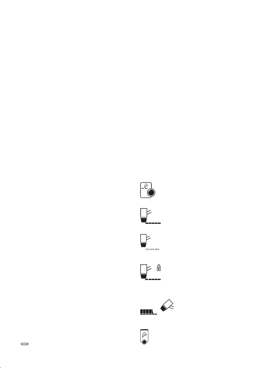
- Type A ( ).
- In order to satisfy the requirements of the EN 61000-3-11 (Flicker)
standard we recommend connecting the power source to interface
points of the main power supply that have an impedance of less than
Zmax = 0.2 ohm.
- The plasma cutting system does not fall within the requisites of IEC/EN
61000-3-12 standard.
Should it be connected to a public mains system, it is the installer’s
responsibility to verify that the plasma cutting system itself is suitable
for connecting to it (if necessary, consult the distribution network
company).
Plug and outlet
Connect the power supply cable to a standard (3P +T) plug of
appropriate capacity and prepare a power supply outlet tted with fuses
or an automatic circuit-breaker; the corresponding earth terminal should
be connected to the (yellow-green) earth conductor of the power supply.
Table 1 (TAB.1) shows the recommended sizes (in amps) of the delayed
mains fuses, to be chosen according to the maximum rated current
output from the power source, and to the rated power supply voltage.
ATTENTION!Failure to comply with the above rules renders
the safety system (class I) ineective, with resulting serious risks for
people (e.g. electric shock) and for property (e.g. re).
CUTTING CIRCUIT CONNECTIONS
ATTENTION!BEFORE CARRYING OUT THE FOLLOWING
CONNECTIONS, MAKE SURE THE CURRENT SOURCE IS OFF AND
DISCONNECTED FROM THE MAINS.
Table 1 (TAB. 1) gives the recommended values for the return cable (in
mm2) according to the maximum energy supplied by the machine.
Compressed air connections (Fig. H).
- Prepare a compressed air distribution line with a working pressure and
minimum capacity indicated in table 2 (TAB. 2).
- Pressure reducer connected as indicated (Fig. E).
IMPORTANT!
Do not exceed the maximum input pressure of 8 bar. Air containing large
quantities of humidity or oil can cause excessive wear of consumable
parts or damage the torch. If in doubt concerning the quality of the
compressed air available, it is recommended to use an air dryer to be
installed downstream of the inlet lter. Use a exible hose to connect the
compressed air line to the machine, using one of the ttings supplied to
be mounted on the air inlet lter at the back of the machine.
Connecting the cutting current return cable.
Connect the cutting current return cable to the piece to be cut or the
metal support bench taking the following precautions:
- Check that a good electric contact is established especially when
cutting sheet metal with insulating, oxidised coatings etc.
- Connect the mass as close as possible to the cutting point.
- Do not use metal structures that are not part of the workpiece as a
cutting current return conductor; this can endanger safety and give
unsatisfactory cutting results.
- Do not connect the mass on the section of the piece to be removed.
Connecting the plasma cutting torch (Fig. F) (were available)
Insert the male end of the torch in the central connector on the front
panel of the machine, making sure the polarisation key is aligned. Fully
tighten the locking ring nut clockwise to guarantee there are no leaks in
the air and current ows.
In some models, the torch is supplied already connected to the current
source.
IMPORTANT!
Before commencing cutting operations, check the consumable parts
are assembled correctly, inspecting the torch head as indicated in the
“TORCH MAINTENANCE”chapter.
WARNING!
USING THE PLASMA CUTTING SYSTEM SAFELY.
Only the torch model as envisaged, coupled with the corresponding
power source as indicated in TAB. 2, are able to guarantee eective
protection by the safety system provided by the manufacturer
(interlocking system).
- DO NOT USE other makes of torch and related consumable parts.
- DO NOT ATTEMPT TO COUPLE THE POWER SOURCE with torches
built for cutting or welding procedures that are not contemplated
in these instructions.
Failure to comply with these rules may cause serious hazards,
endangering the physical safety of the user and damaging the
apparatus.
6. PLASMA CUTTING:PROCESS DESCRIPTION
The plasma arc and plasma cutting application principle.
Plasma is a gas heated to an extremely high temperature and ionised
so that it becomes an electrical conductor. This cutting procedure uses
plasma to transfer the electric arc to the metal piece that is melted by the
heat and separated. The torch uses compressed air supplied by a single
source, both for plasma gas and for cooling and protection gas.
Starting the pilot arc
The cycle is started by a pilot current that ows between the electrode
(polarity -) and the torch nozzle (polarity +) and the start of the air ow.
Approaching the torch to the piece to be cut, connected to the current
source polarity (+), the pilot arc is transferred and creates a plasma arc
between the electrode (-) and the piece itself (cutting arc). The pilot arc is
excluded as soon as the cutting arc is established between the electrode
and the piece.
The factory setting stay time of the pilot arc is 2 seconds (4 seconds in
GOUGING mode); if the arc transfer to the piece is not eected within this
time, the cycle is automatically blocked, maintaining the cooling air.
To start the cycle again, release the torch button and press it again.
Preliminary procedures.
Before commencing cutting operations, check the consumable parts
are assembled correctly, inspecting the torch head as indicated in the
“TORCH MAINTENANCE”paragraph.
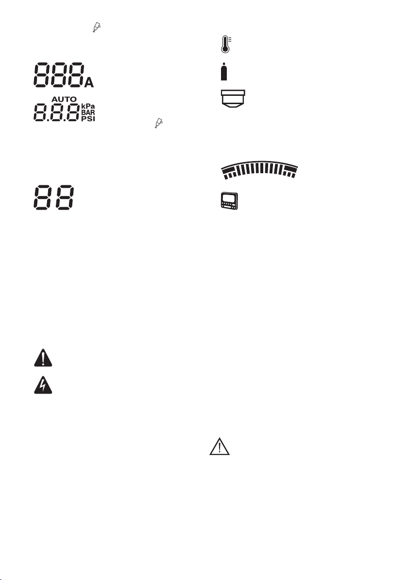
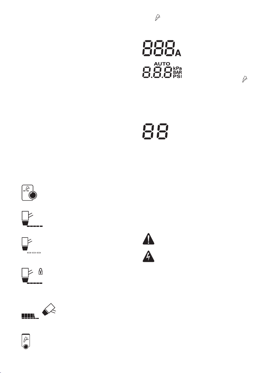
- Turn on the current supply and set the cutting current (Fig. D-1)
according to the thickness and type of metal material to be cut.
- Press the air button (Fig. C-3) to start the air ow.
- During this phase, adjust the air pressure until the pressure value
required for the type of torch being used is visible on the display (TAB.
2).
- Adjust the knob: pull upwards to release it and then turn it to adjust
the pressure to the value indicated in theTORCH TECHNICAL DATA.
- Read the required value on the pressure gauge and then press the knob
to lock the setting.
- Allow the air ow to end spontaneously to make it easier to remove any
condensate accumulated in the torch.
Cutting procedure (Fig. L).
- Approach the torch nozzle to the edge of the piece (about 2 mm), and
press the torch button; the pilot arc is triggered after about 1 second.
- If the distance is suitable, the pilot arc is immediately transferred to the
piece giving rise to the cutting arc.
- Move the torch on the surface of the piece along the ideal cutting line
at a regular pace.
- Adjust the cutting rate according to the thickness and selected current,
checking that the arc exiting the lower surface of the piece is inclined
by 5-10 degrees in relation to the vertical line, in the opposite direction
to the operating direction.
Grid cutting procedure (where applicable)
This function can be useful when cutting perforated or grid metal sheets:
- Use the “select mode”button (Fig. C-2) to select the grid cutting mode.
On completing the cutting cycle, keeping the torch button pressed, the
pilot arc will restart automatically. Only use this function when required

- 9 -
to avoid unnecessary use of the electrode and nozzle.
ATTENTION!In this mode you are advised to use standard
sized electrodes and nozzles.
In particular conditions, using elongated electrodes and nozzles
could cause interruption of the cutting arc.
Perforation (Fig. M)
To perform this operation or start cutting from the piece centre, start
with the torch inclined at an angle and move it progressively to a vertical
position.
- This procedure prevents the arc or smelted particles returns from
ruining the nozzle hole which will rapidly compromise its performance.
- Perforation of pieces with a thickness of up to 25% of the maximum
foreseen for the range of use can be performed directly.
7. MAINTENANCE
ATTENTION!BEFORE CARRYING OUT MAINTENANCE
WORK, MAKE SURE THAT THE PLASMA CUTTING SYSTEM IS
SWITCHED OFF AND DISCONNECTED FROM THE POWER SUPPLY.
ROUTINE MAINTENANCE
ROUTINE MAINTENANCE WORK CAN BE PERFORMED BY THE
OPERATOR.
TORCH (Fig. N)
Check the wear level of the torch parts used by the plasma arc regularly,
depending on the level of use or if any cutting defects arise.
1- Spacer.
Replace if deformed or covered in slag to an extent that makes it
impossible for the torch to maintain a correct position (distance and
perpendicularity).
2- Nozzle holder.
Unscrew it from the torch head by hand. Clean thoroughly or replace it
if damaged (burns, deformation or cracks). Check the condition of the
upper metal section (torch safety actuator).
3- Nozzle /Hood.
Check the wear level of the plasma arc ow hole and the internal
and external surfaces. Replace the nozzle if the hole has widened
compared to the original diameter or is deformed. If the surfaces are
particularly oxidised, clean them using ne grain sanding paper.
4- Air distributor ring.
Check there are no burns or cracks and that the airow holes are not
blocked. Replace immediately if damaged.
5- Electrode.
Replace the electrode when the depth of the crater that forms on the
emission surface reaches about 1.5 mm (Fig. O).
6- Air distributor pipe.
Check there are no burns or cracks and that the airow holes are not
blocked. Replace immediately if damaged.
7- Torch body, handgrip and cable.
Normally these components do not require any particular
maintenance except periodic inspection and thorough cleaning
without using solvents of any nature. If the insulation is damaged
showing cracks or burns or the electric conductors are loose, the torch
can no longer be used due to lack of conformity with the required
safety conditions.
In this case, repairs (extraordinary maintenance) can not be performed
on-site, as they must be performed by an authorised service centre
capable of conducting the special tests after the repair.
To maintain the torch in good working condition, some fundamental
precautions must be taken:
- do not bring the torch or cable in contact with hot or scorching
parts.
- do not apply excessive strain on the cable.
- do not lay the cable on sharp corners, points or abrasive surfaces.
- wind the cable into regular coils if it is longer than required.
- do not allow any vehicle to drive over the cable and do not tread on
it.
Attention.
- Before performing any work on the torch, allow it to cool down for at
least the“post-air” time.
- Except in particular cases, it is recommended to replace the electrode
and nozzle concurrently.
- Follow the torch components assembly order (reverse order compared
to the disassembly procedure).
- Make sure that the distributor ring is mounted in the right direction.
- Replace the nozzle holder screwing it on by hand applying light
pressure.
- Never replace the nozzle holder without having mounted the
electrode, the distributor ring and the nozzle.
- Avoid leaving the pilot arc on when not in use so as to prevent wear
and tear of the electrode, the diuser and the nozzle.
- Do not use excessive force when tightening the electrode as this can
damage the torch.
- Timely and correct wear controls on the torch consumable parts are
vital for the safety and operational functions of the cutting system.
- If the insulation is damaged showing cracks or burns or the electric
conductors are loose, the torch can no longer be used due to lack of
conformity with the required safety conditions. In this case, repairs
(extraordinary maintenance) can not be performed on-site, as they
must be performed by an authorised service centre capable of
conducting the special tests after the repair.
Compressed air lter (Fig. H)
- The lter has an automatic condensate exhaust that is activated every
time it is disconnected from the compressed air supply.
- Inspect the lter regularly; if there is any water in the glass, try bleeding
it manually pushing the exhaust tting upwards.
- If the lter cartridge is particularly dirty, it must be replaced to avoid
excessive load losses.
EXTRAORDINARY MAINTENANCE
EXTRAORDINARY MAINTENANCE MUST ONLY BE CARRIED OUT BY
TECHNICIANS WHO ARE EXPERT OR QUALIFIED IN THE ELECTRIC-
MECHANICAL FIELD, AND IN FULL RESPECT OF THE IEC/EN 60974-4
TECHNICAL DIRECTIVE
WARNING!BEFORE REMOVING THE MACHINE PANELS AND
WORKING INSIDE IT MAKE SURE THAT IT HAS BEEN SWITCHED OFF
AND DISCONNECTED FROM THE MAIN POWER SUPPLY.
If checks are carried out inside the machine while it is live, this may
cause serious electric shock due to direct contact with live parts.
- Inspect the inside of the machine regularly, with a frequency depending
on the amount of use and dust in the environment, and remove
dust that has deposited on the transformer, rectier, inductance and
resistors, using a jet of dry compressed air (max 10 bar).
- Do not direct the jet of compressed air onto the electronic boards;
these can be cleaned with a very soft brush or suitable solvents.
- Take the opportunity to make sure the electrical connections are tight
and there is no damage to the wiring insulation.
- Make sure the compressed air circuit hoses and connections are intact
and leak-free.
- When these operations have been completed, re-assemble the panels
on the machine and tighten the fastening screws right down.
- Never ever carry out cutting operations with the machine open.
- After having carried out maintenance or repairs, restore the connections
and wiring as they were before, making sure they do not come into
contact with moving parts or parts that can reach high temperatures.
Tie all the wires as they were before, being careful to keep the high
voltage connections of the primary transformer separate from the low
voltage ones of the secondary transformer.
Use all the original washers and screws when closing the casing.
8. TROUBLESHOOTING
IN THE CASE OF UNSATISFACTORY OPERATION, AND BEFORE CARRYING
OUT MORE SYSTEMATIC TESTS OR CONTACTINGYOUR SERVICING CENTRE
CARRY OUT THE FOLLOWING CHECKS:
- Check whether the yellow LED is ON, indicating triggering of the
thermal cutout, over- or under-voltage or shorting.
- Make sure that the nominal duty cycle has been respected; if the
thermal cutout triggers, wait until the machine cools down naturally
then make sure the fan is working properly.
- Check the power supply voltage: if it is too high or too low the machine
will not work.
- Make sure there is no shorting at machine output: if there is shorting
remove the cause.
- Make sure the cutting circuit connections are correct, in particular
that the earth cable clamp is actually connected to the piece with no
insulating material in between (e.g. paint).

- 10 -
MOST COMMONLY OCCURRING CUTTING DEFECTS
During cutting operations it is possible that defects occur, which are
not normally caused by operating faults in the system but by other
operational matters such as:
a- Insucient penetration or excessive slag formation:
- Cutting rate too high.
- Over-inclined torch.
- Piece too thick or cutting current too low.
- In appropriate compressed air pressure-ow.
- Worn electrode and torch nozzle.
- Inappropriate nozzle-holder tip.
b- Arc transfer failure:
- Worn electrode.
- Poor contact of the return cable terminal clamp.
c- Interrupted cutting arc:
- Cutting rate too low.
- Torch-piece distance too high.
- Worn electrode.
- A safeguard has triggered.
d- Inclined cut (not perpendicular):
- Incorrect torch position.
- Asymmetric wear on nozzle hole and/or incorrect assembly of torch
components.
- Inappropriate air pressure.
e- Excessive nozzle and electrode wear:
- Air pressure too low.
- Contaminated air (moisture-oil).
- Damaged nozzle holder.
- Too many pilot arc strikes in air.
- Excessive cutting rate with melted particles returning onto torch
components.
(IT)
MANUALE ISTRUZIONE
ATTENZIONE!PRIMA DI UTILIZZARE IL SISTEMA DI TAGLIO AL
PLASMA LEGGERE ATTENTAMENTE IL MANUALE DI ISTRUZIONE!
SISTEMI DI TAGLIO AL PLASMA PREVISTI PER USO PROFESSIONALE
E INDUSTRIALE
1. SICUREZZA GENERALE PER IL TAGLIO AD ARCO PLASMA
L’operatore deve essere sucientemente edotto sull’uso sicuro
dei sistemi di taglio al plasma ed informato sui rischi connessi ai
procedimenti per saldatura ad arco e tecniche connesse, alle relative
misure di protezione ed alle procedure di emergenza.
(Fare riferimento anche alla norma “EN 60974-9:Apparecchiature
per saldatura ad arco. Parte 9:Installazione ed uso”).
- Evitare i contatti diretti con il circuito di taglio;la tensione a vuoto
fornita dal sistema di taglio plasma puòessere pericolosa in
talune circostanze.
- La connessione dei cavi del circuito di taglio, le operazioni di
verica e di riparazione devono essere eseguite con il sistema di
taglio spento e scollegato dalla rete di alimentazione.
- Spegnere il sistema di taglio al plasma e scollegarlo dalla rete di
alimentazione prima di sostituire i particolari d’usura della torcia.
- Eseguire l’installazione elettrica secondo le previste norme e leggi
antinfortunistiche.
- Il sistema di taglio al plasma deve essere collegato esclusivamente
ad un sistema di alimentazione con conduttore di neutro collegato
a terra.
- Assicurarsi che la presa di alimentazione sia correttamente
collegata alla terra di protezione.
- Non utilizzare il sistema di taglio al plasma in ambienti umidi o
bagnati o sotto la pioggia.
- Non utilizzare cavi con isolamento deteriorato o con connessioni
allentate.
- Non tagliare su contenitori, recipienti o tubazioni che contengano
o che abbiano contenuto prodotti inammabili liquidi o gassosi.
- Evitare di operare su materiali puliti con solventi clorurati o nelle
vicinanze di dette sostanze.
- Non tagliare su recipienti in pressione.
- Allontanare dall’area di lavoro tutte le sostanze inammabili (p.es.
legno, carta, stracci, etc.)
- Assicurarsiun ricambio d’ariaadeguatoodi mezzi atti adasportare
i fumi prodotti dalle operazioni di taglio al plasma;ènecessario un
approccio sistematico per la valutazione dei limiti all’esposizione
dei fumi prodotti dalle operazioni di taglio in funzione della loro
composizione, concentrazione e durata dell’esposizione stessa.
- Adottare un adeguato isolamento elettrico rispetto l’ugello della
torcia di taglio plasma, il pezzo in lavorazione ed eventuali parti
metalliche messe a terra poste nelle vicinanze (accessibili).
Ciòènormalmente ottenibile indossando guanti, calzature,
copricapo ed indumenti previsti allo scopo e mediante l’uso di
pedane o tappeti isolanti.
- Proteggere sempre gli occhi con gli appositi ltri conformi alla UNI
EN 169 o UNI EN 379 montati su maschere o caschi conformi alla
UNI EN 175.
Usare gli appositi indumenti ignifughi protettivi (conformi alla
UNI EN 11611) e guanti di saldatura (conformi alla UNI EN 12477)
evitando di esporre l’epidermide ai raggi ultravioletti ed infrarossi
prodotti dall’arco;la protezione deve essere estesa ad altre
persone nelle vicinanze dell’arco per mezzo di schermi o tende
non riettenti.
- Rumorosità:Se a causa di operazioni di taglio particolarmente
intensive viene vericato un livello di esposizione quotidiana
personale (LEPd) uguale o maggiore a 85db(A), èobbligatorio
l’uso di adeguati mezzi di protezione individuale (Tab. 1).

- 11 -
- Il passaggio della corrente di taglio provoca l’insorgere di campi
elettromagnetici (EMF) localizzati nei dintorni del circuito di taglio.
I campi elettromagnetici possono interferire con alcune
apparecchiature mediche (es. Pace-maker, respiratori, protesi
metalliche etc.).
Devono essere prese adeguate misure protettive nei confronti dei
portatori di queste apparecchiature. Ad esempio proibire l’accesso
all’area di utilizzo del sistema di taglio al plasma.
Questo sistema di taglio al plasma soddisfa gli standard tecnici
di prodotto per l’uso esclusivo in ambiente industriale a scopo
professionale. Non èassicurata la rispondenza ai limiti di base
relativi all’esposizione umana ai campi elettromagnetici in ambiente
domestico.
L’operatore deve utilizzare le seguenti procedure in modo da ridurre
l’esposizione ai campi elettromagnetici:
- Fissare insieme il piùvicino possibile i due cavi.
- Mantenere la testa ed il tronco del corpo il piùdistante possibile
dal circuito di taglio.
- Non avvolgere mai i cavi attorno al corpo.
- Non tagliare con il corpo in mezzo al circuito di taglio. Tenere
entrambi i cavi dalla stessa parte del corpo.
- Collegare il cavo di ritorno della corrente di taglio al pezzo da
tagliare il piùvicino possibile al giunto in esecuzione.
- Non tagliare vicino, seduti o appoggiati al sistema di taglio al
plasma (distanza minima:50cm).
- Non lasciare oggetti ferromagnetici in prossimità del circuito di
taglio.
- Distanza minima d=20cm (Fig. P).
- Apparecchiatura di classe A:
Questo sistema di taglio al plasma soddisfa i requisiti dello standard
tecnico di prodotto per l’uso esclusivo in ambiente industriale
e a scopo professionale. Non èassicurata la rispondenza alla
compatibilità elettromagnetica negli edici domestici e in quelli
direttamente collegati a una rete di alimentazione a bassa tensione
che alimenta gli edici per l’uso domestico.
PRECAUZIONI SUPPLEMENTARI
LE OPERAZIONI DI TAGLIO AL PLASMA:
- In ambiente a rischio accresciuto di shock elettrico;
- In spazi connati;
- In presenza di materiali inammabili o esplodenti;
DEVONO essere preventivamente valutate da un
”Responsabile esperto”ed eseguiti sempre con la presenza di
altre persone istruite per interventi in caso di emergenza.
DEVONO essere adottati i mezzi tecnici di protezione descritti
in 7.10;A.8;A.10 della norma “EN 60974-9:Apparecchiature
per saldatura ad arco. Parte 9:Installazione ed uso”.
- DEVONO essere proibite le operazioni di taglio mentre la sorgente
di corrente èsostenuta dall’operatore (es. per mezzo di cinghie).
- DEVONO essere proibite le operazioni di taglio con operatore
sollevato da terra, salvo eventuale uso di piattaforme di sicurezza.
- ATTENZIONE!SICUREZZA DEL SISTEMA PER TAGLIO PLASMA.
Solo il modello di torcia previsto ed il relativo abbinamento con la
sorgente di corrente come indicato sui ”DATI TECNICI”garantisce
che le sicurezze previste dal costruttore siano ecaci (sistema di
interblocco).
- NON UTILIZZARE torce e relative parti di consumo di diversa
origine.
- NON TENTARE DI ACCOPPIARE ALLA SORGENTE DI CORRENTE torce
costruite per procedimenti di taglio o SALDATURA non previsti in
queste istruzioni.
- IL MANCATO RISPETTO DI QUESTE REGOLE puòdare luogo a
GRAVI pericoli per la sicurezza sica dell’utente e danneggiare
l’apparecchiatura.
RISCHI RESIDUI
- RIBALTAMENTO:collocare la sorgente di corrente per taglio al
plasma su una superce orizzontale di portata adeguata alla
massa;in caso contrario (es. pavimentazioni inclinate, sconnesse
etc...) esiste il pericolo di ribaltamento.
- USO IMPROPRIO:èpericolosa l’utilizzazione del sistema di taglio
plasma per qualsiasi lavorazione diversa da quella prevista.
- È vietato il sollevamento del sistema di taglio al plasma se non
sono stati preventivamente smontati tutti i cavi/tubazioni di
interconnessioni o di alimentazione.
- È vietato utilizzare la maniglia come mezzo di sospensione del
sistema di taglio al plasma.
2. INTRODUZIONE E DESCRIZIONE GENERALE
Sistema di taglio al plasma ad aria compressa, trifase ventilato. Consente
il taglio veloce senza deformazione su acciaio, acciaio inox, acciai
galvanizzati, alluminio, rame, ottone, ecc. Il ciclo di taglio è attivato da un
arco pilota.
PRINCIPALI CARATTERISTICHE
- Regolazione della corrente di taglio.
- Dispositivo di controllo tensione in torcia.
- Dispositivo di controllo pressione aria, cortocircuito torcia.
- Protezione termostatica.
- Visualizzazione della pressione aria.
- Comando rareddamento torcia.
- Sovratensione, sottotensione, mancanza fase.
- Connettore comando remoto.
ACCESSORI DI SERIE
- Torcia per taglio plasma.
- Kit raccordi per allacciamento aria compressa.
ACCESSORI A RICHIESTA
- Kit elettrodi-ugelli di ricambio.
- Torcia alto usso d’aria.
- Kit elettrodi-ugelli di ricambio per torcia alto usso d’aria.
- Kit gouging.
3. DATI TECNICI
TARGA DATI
I principali dati relativi all’impiego e alle prestazioni del sistema di taglio al
plasma sono riassunti nella targa caratteristiche col seguente signicato:
Fig. A
1- Norma EUROPEA di riferimento per la sicurezza e la costruzione delle
macchine per saldatura ad arco e taglio al plasma.
2- Simbolo della struttura interna della macchina.
3- Simbolo del procedimento di taglio plasma.
4- Simbolo S: indica che possono essere eseguite operazioni di taglio in
un ambiente con rischio accresciuto di shock elettrico (p.es. in stretta
vicinanza di grandi masse metalliche).
5- Simbolo della linea di alimentazione:
1~: tensione alternata monofase
3~: tensione alternata trifase
6- Grado di protezione dell’involucro.
7- Dati caratteristici della linea di alimentazione:
- U1 :Tensione alternata e frequenza di alimentazione della
macchina (limiti ammessi ±10%):
- I1 max :Corrente massima assorbita dalla linea.
- I1e :Corrente eettiva di alimentazione
8- Prestazioni del circuito di taglio:
- U0:tensione massima a vuoto (circuito di taglio aperto).
- I2/U2 :Corrente e tensione corrispondente normalizzata che
possono venire erogate dalla macchina durante il taglio.
- X :Rapporto d’intermittenza: indica il tempo durante il quale
la macchina può erogare la corrente corrispondente (stessa
colonna). Si esprime in %, sulla base di un ciclo di 10min (p.es.
60% = 6 minuti di lavoro, 4 minuti sosta; e così via).
Nel caso i fattori d’utilizzo (di targa, riferiti a 40°C ambiente)
vengano superati si determinerà l’intervento della protezione
termica ( la macchina rimane in stand-by nché la sua
temperatura non rientri nei limiti ammessi .
- A/V-A/V:Indica la gamma di regolazione della corrente di taglio
(minimo - massimo) alla corrispondente tensione d’arco.
9- Numero di matricola per l’identicazione della macchina
(indispensabile per assistenza tecnica, richiesta ricambi, ricerca
origine del prodotto).
10- :Valore dei fusibili ad azionamento ritardato da prevedere per

- 12 -
la protezione della linea
11- Simboli riferiti a norme di sicurezza il cui signicato è riportato nel
capitolo 1“Sicurezza generale per la saldatura ad arco”.
Nota: L’esempio di targa riportato è indicativo del signicato dei simboli
e delle cifre; i valori esatti dei dati tecnici del sistema di taglio al plasma
in vostro possesso devono essere rilevati direttamente sulla targa della
macchina stessa.
ALTRI DATI TECNICI:
- SORGENTE DI CORRENTE :vedi tabella 1 (TAB.1)
- TORCIA :vedi tabella 2 (TAB.2)
Il peso della macchina èriportato in tabella 1 (TAB. 1).
4. DESCRIZIONE DEL SISTEMA DI TAGLIO AL PLASMA
Dispositivi di controllo, regolazione e connessione
SORGENTE DI CORRENTE (Fig. B)
1 - Torcia con attacco diretto o centralizzato.
- Il pulsante torcia è l’unico organo di controllo da cui può essere
comandato l’inizio e l’arresto delle operazioni di taglio.
- Al cessare dell’azione sul pulsante il ciclo viene interrotto
istantaneamente in qualunque fase salvo il mantenimento dell’aria
di rareddamento (post-aria).
- Manovre accidentali: per dare il consenso di inizio ciclo, l’azione sul
pulsante dev’essere esercitata per un tempo minimo.
- Sicurezza elettrica: la funzione del pulsante è inibita se il portaugello
isolante NON è montato sulla testa della torcia, o il suo montaggio è
scorretto.
2 - Cavo di ritorno.
3 - Pannello di controllo.
PANNELLO DI CONTROLLO (Fig. C)
1 - Encoder e Tasto
Funzione encoder:
In qualsiasi modalità permette la regolazione della corrente.
Funzione tasto:
In qualsiasi modalità permette l’impostazione dell’unità di misura
adottata dal sensore di pressione.
2 - Tasto selezione Modi
Permette di selezionare i modi (Fig. D):
TAGLIO
Modalità standard di funzionamento.
TAGLIO GRIGLIATO
Modalità di taglio ad arco mantenuto anche quando non viene
trasferito al pezzo.
TAGLIO BLOCCATO
Modalità simile al taglio, con la dierenza che, appena instaurato
l’arco di taglio il pulsante torcia può essere rilasciato. Il taglio si
interrompe se viene nuovamente premuto il tasto torcia.
GOUGING
Modalità scriccatura, adatta all’uso con torcia provvista di
consumabili GOUGING.
3 - Tasto ARIA
Premendo questo tasto, l’aria continua ad uscire dalla torcia per circa
45sec ( acceso). Durante questa fase regolare la pressione nel
range richiesto dalla torcia.
Display (Fig. D)
1 - Visualizzazione della corrente
2 - Visualizzazione della pressione aria manometro digitale
- Premere il tasto aria per far fuoriuscire l’aria dalla torcia (
acceso).
Impostare la pressione al valore richiesto agendo sulla manopola
del riduttore di pressione (Fig. E-3).
- Tirare verso l’alto per sbloccare e ruotare (Fig. E-3).
Se la pressione impostata è fuori dal range richiesto compare un
warning (Fig. D-3).
- Al termine della regolazione spingere verso il basso la manopola
per bloccare la regolazione (Fig. E-3).
3 - Codice allarmi, avviso con blocco potenza (TAB. 3).
Il ripristino dalla condizione di allarme o di warning avviene
tipicamente dopo 10 secondi dalla scomparsa della causa che lo ha
generato.
01: Intervento protezione termica circuito primario.
02: Intervento protezione termica circuito secondario.
03: Intervento protezione per sovratensione linea di alimentazione.
04: Intervento protezione per sottotensione linea di alimentazione.
05: Intervento protezione termica componenti magnetici.
06: Intervento mancanza fase linea di alimentazione.
08: Tensione ausiliaria fuori range.
09: Intervento protezione pressostato circuito aria.
15: Intervento circuito di sicurezza torcia.
Codice warning, avviso senza blocco potenza:
07: Segnalazione eccessivo deposito di polvere interno alla
macchina
11: Segnalazione usura Torcia / Consumabile.
14: Segnalazione errore nei dati seriali.
16: Segnalazione pressione circuito aria fuori intervallo ottimale.
17: Segnalazione instabilità linea di alimentazione.
4 - Presenza allarme o warning
5 - Uscita macchina energizzata
Quando acceso indica uscita macchina energizzata: circuito di taglio
attivato (Arco pilota o Arco taglio attivo).
L’uscita viene energizzata quando viene premuto il pulsante torcia e
non è presente nessuna condizione di allarme.
L’uscita macchina non è energizzata nei seguenti casi:
- con pulsante torcia NON premuto (condizione di stand by).
- nei modi TAGLIO, TAGLIO BLOCCATO e GOUGING durante il post
gas (10 secondi).
- in qualsiasi condizione di allarme.
La macchina disabilita l’uscita nei seguenti casi:
- nei modi TAGLIO, TAGLIO GRIGLIATO e GOUGING al rilascio del
pulsante torcia.
- in modo TAGLIO BLOCCATO al rilascio del pulsante torcia durante
l’arco pilota o alla pressione del pulsante torcia durante l’arco di
taglio.
- se l’arco pilota non viene trasferito al pezzo entro il tempo massimo
di 2 secondi (4 secondi in modo GOUGING).
- nei modi TAGLIO, TAGLIO BLOCCATO e GOUGING se l’arco di taglio
si interrompe per eccessiva distanza torcia pezzo, eccessiva usura
dell’elettrodo o allontanamento forzato della torcia dal pezzo (in
modo TAGLIO GRIGLIATO l’arco viene sempre mantenuto).

- 13 -
- in modo TAGLIO GRIGLIATO se al termine di un ciclo di taglio, il
successivo non avviene entro 10 secondi.
- se interviene un allarme.
6 - Protezione termostatica
7 - Mancanza aria
8 - Consumabili danneggiati
Warning consumabili malfunzionanti le cause possono essere:
- usura dei consumabili.
- consumabili montati erroneamente.
- torcia difettosa.
- pressione aria troppo bassa.
Il ripristino da questo warning avviene dopo un ciclo di taglio
corretto.
9 - Manometro Analogico
10 - Presenza comando remoto
Si accende quando viene immesso uno dei seguenti segnali remoti
sul connettore posteriore (Fig. E-3):
1- Una connessione seriale tipo MODBUS.
2- Un comando esterno abilitazione potenza.
3- Un segnale per impostazione di corrente maggiore o uguale a
1V.
PANNELLO POSTERIORE (Fig. E)
1 - Interruttore generale O - I
In posizione I (ON) macchina pronta per il funzionamento,
2 - Regolatore di pressione (aria compressa plasma) manuale.
3 - Manopola del riduttore di pressione.
4 - Cavo di alimentazione.
5 - Comando remoto 14 poli.
PIN 1 Polarizzatore
PIN 2.3 MODBUS Rs485.
PIN 4.5 Contatto Arco taglio. Normalmente aperto, si chiude quando
l’arco di taglio è attivo.
PIN 6.7 Contatto Arco pilota. Normalmente aperto, si chiude quando
l’arco pilota è attivo.
PIN 8 Comando esterno abilitazione potenza. Se chiuso a 0[V]
(PIN12) abilità la potenza. Sostituisce completamente la funzione del
pulsante torcia.
PIN 9 Segnale OUT tensione uscita. Range 0-10[V] con scala
impostabile 10V/200V, 10V/300V, 10V/400V, 10V/500V.
L’impostazione avviene premendo simultaneamente durante l’avvio
della scheda i tasti “Encoder e selezioni Modi”. Selezionare la scala
desiderata agendo con l’encoder. Ripremere il tasto“selezione modi”
per uscire.
PIN10 Segnale IN impostazione corrente 1[V] / Imax/10 [A].
PIN11 Segnale OUT pressione aria 1 [V]/[BAR] range 0..10 [V]
PIN12 Riferimento 0[V] segnali PIN 8,9,10,11 e 13.
PIN13 Alimentazione 12[V] max 100mA.
PIN14 PE conduttore di protezione.
5. INSTALLAZIONE
ATTENZIONE!ESEGUIRE TUTTE LE OPERAZIONI DI
INSTALLAZIONE ED ALLACCIAMENTI ELETTRICI CON IL SISTEMA
DI TAGLIO AL PLASMA RIGOROSAMENTE SPENTO E SCOLLEGATO
DALLA RETE DI ALIMENTAZIONE.
GLI ALLACCIAMENTI ELETTRICI DEVONO ESSERE ESEGUITI
ESCLUSIVAMENTE DA PERSONALE ESPERTO O QUALIFICATO.
Assemblaggio cavo di ritorno-pinza di massa (Fig. G)
UBICAZIONE DELLA MACCHINA
Individuare il luogo d’installazione della macchina in modo che non
vi siano ostacoli in corrispondenza della apertura d’ingresso e d’uscita
dell’aria di rareddamento; accertarsi nel contempo che non vengano
aspirate polveri conduttive, vapori corrosivi, umidità, etc..
Mantenere almeno 250mm di spazio libero attorno alla macchina.
ATTENZIONE!Posizionare la macchina su di una superce
piana di portata adeguata al peso per evitarne il ribaltamento o
spostamenti pericolosi.
COLLEGAMENTO ALLA RETE
- Prima di eettuare qualsiasi collegamento elettrico, vericare che i
dati di targa della sorgente di corrente corrispondano alla tensione e
frequenza di rete disponibili nel luogo d’installazione.
- La sorgente di corrente deve essere collegata esclusivamente ad un
sistema di alimentazione con conduttore di neutro collegato a terra.
- Per garantire la protezione contro il contatto indiretto usare interuttori
dierenziali del tipo:
- Tipo A ( ).
- Al ne di soddisfare i requisiti della Norma EN 61000-3-11 (Flicker)
si consiglia il collegamento della sorgente di corrente ai punti di
interfaccia della rete di alimentazione che presentano un’impedenza
minore di Zmax = 0.2 ohm.
- Il sistema di taglio al plasma non rientra nei requisiti della norma IEC/EN
61000-3-12.
Se essa viene collegata a una rete di alimentazione pubblica, è
responsabilità dell’installatore o dell’utilizzatore vericare che il sistema
di taglio al plasma possa essere connesso (se necessario, consultare il
gestore della rete di distribuzione).
Spina e presa
Collegare al cavo di alimentazione una spina normalizzata, (3P +T)
di portata adeguata e predisporre una presa di rete dotata di fusibili
o interruttore automatico; l’apposito terminale di terra deve essere
collegato al conduttore di terra (giallo-verde) della linea di alimentazione.
La tabella 1 (TAB.1) riporta i valori consigliati in ampere dei fusibili
ritardati di linea scelti in base alla massima corrente nominale erogata
della sorgente di corrente, e alla tensione nominale di alimentazione.
ATTENZIONE!L’inosservanza delle regole sopraesposte
rende inecace il sistema di sicurezza previsto dal costruttore (classe
I) con conseguenti gravi rischi per le persone (es. shock elettrico) e
per le cose (es. incendio).
CONNESSIONI DEL CIRCUITO DI TAGLIO
ATTENZIONE!PRIMA DI ESEGUIRE I SEGUENTI
COLLEGAMENTI ACCERTARSI CHE LA SORGENTE DI CORRENTE SIA
SPENTA E SCOLLEGATA DALLA RETE DI ALIMENTAZIONE.
La Tabella 1 (TAB. 1)riporta i valori consigliati per il cavo di ritorno (in
mm2) in base alla massima corrente erogata dalla macchina.
Allacciamento aria compressa (Fig. H).
- Predisporre una linea di distribuzione aria compressa con pressione e
portata minime indicate in tabella 2 (TAB. 2).
- Connettere riduttore di pressione come indicato (Fig. E).
IMPORTANTE!
Non superare la pressione massima d’ingresso di 8 bar. Aria contenente
quantità notevoli di umidità o di olio può causare un’usura eccessiva
delle parti di consumo o danneggiare la torcia. Se esistono dubbi sulla
qualità dell’aria compressa a disposizione è consigliabile l’utilizzo di un
essicatore d’aria, da installare a monte del ltro d’ingresso. Collegare, con
una tubazione essibile, la linea aria compressa alla macchina, utilizzando
uno dei raccordi in dotazione da montare sul ltro aria d’ingresso, posto
sul retro della macchina.
Collegamento cavo di ritorno della corrente di taglio.
Collegare il cavo di ritorno della corrente di taglio al pezzo da tagliare o al
banco metallico di sostegno osservando le seguenti precauzioni:
- Vericare che venga stabilito un buon contatto elettrico in particolare
se vengono tagliate lamiere con rivestimenti isolanti, ossidate, etc.
- Eseguire il collegamento di massa il più vicino possibile alla zona di
taglio.

- 14 -
- L’utilizzazione di strutture metalliche non facenti parte del pezzo in
lavorazione, come conduttore di ritorno della corrente di taglio, può
essere pericolosa per la sicurezza e dare risultati insucienti nel taglio.
- Non eseguire il collegamento di massa sulla parte del pezzo che deve
essere asportata.
Collegamento della torcia per taglio plasma (Fig. F) (ove previsto)
Inserire il terminale maschio della torcia nel connettore centralizzato
posto su pannello frontale della macchina, facendo combaciare la chiave
di polarizzazione. Avvitare a fondo, in senso orario, la ghiera di bloccaggio
per garantire il passaggio di aria e corrente senza perdite.
In alcuni modelli la torcia viene fornita già collegata alla sorgente di
corrente.
IMPORTANTE!
Prima di iniziare le operazioni di taglio, vericare il corretto montaggio
delle parti di consumo ispezionando la testa della torcia come indicato
nel capitolo ”MANUTENZIONE TORCIA”.
ATTENZIONE!
SICUREZZA DEL SISTEMA TAGLIO PLASMA.
Solo il modello di torcia previsto ed il relativo abbinamento con
la sorgente di corrente come indicato in TAB. 2 garantisce che
le sicurezze previste dal costruttore siano ecaci (sistema di
interblocco).
- NON UTILIZZARE torce e relative parti di consumo di diversa
origine.
- NON TENTARE DI ACCOPPIARE ALLA SORGENTE DI CORRENTE
torce costruite per procedimenti di taglio o saldatura non previsti
in queste istruzioni.
Il mancato rispetto di queste regole puòdare luogo a gravi pericoli
per la sicurezza sica dell’utente e danneggiare l’apparecchiatura.
6. TAGLIO AL PLASMA:DESCRIZIONE DEL PROCEDIMENTO
L’arco plasma e principio di applicazione nel taglio plasma.
Il plasma è un gas riscaldato a temperatura estremamente elevata e
ionizzato in modo da diventare elettricamente conduttore. Questo
procedimento di taglio utilizza il plasma per trasferire l’arco elettrico al
pezzo metallico che viene fuso dal calore e separato. La torcia utilizza aria
compressa proveniente da una singola alimentazione sia
per il gas plasma sia per il gas di rareddamento e protezione.
Innesco arco pilota
La partenza del ciclo è determinato da una corrente pilota che uisce tra
l’elettrodo (polarità -) e l’ugello della torcia (polarità +) e la partenza del
usso d’aria.
Avvicinando la torcia al pezzo da tagliare, collegato alla polarità (+) della
sorgente di corrente, l’arco pilota viene trasferito instaurando un arco
plasma tra elettrodo (-) ed il pezzo stesso (arco di taglio). L’ arco pilota
viene escluso non appena l’arco di taglio si stabilisce tra elettrodo e pezzo.
Il tempo di mantenimento dell’arco pilota impostato in fabbrica è di 2sec
(4secondi in modo GOUGING); se il trasferimento dell’arco al pezzo non è
eettuato entro questo tempo il ciclo viene automaticamente bloccato
salvo il mantenimento dell’aria di rareddamento.
Per iniziare di nuovo il ciclo è necessario rilasciare il pulsante torcia e
ripremerlo.
Operazioni preliminari.
Prima di iniziare le operazioni di taglio, vericare il corretto montaggio
delle parti di consumo ispezionando la testa della torcia come indicato
nel paragrafo ”MANUTENZIONE TORCIA”.
- Accendere la sorgente di corrente ed impostare la corrente di taglio
(Fig. D-1) in base allo spessore e al tipo di materiale metallico che si
intende tagliare.
- Premere il pulsante aria (Fig. C-3) dando luogo all’eusso aria.
- Regolare, durante questa fase, la pressione dell’aria sino a leggere sul
display il valore di pressione richiesto in base alla torcia utilizzata (TAB.
2).
- Agire sulla manopola: tirare verso l’alto per sbloccare e ruotare per
regolare la pressione al valore indicato sui DATI TECNICI TORCIA.
- Leggere il valore richiesto sul manometro; spingere la manopola per
bloccare la regolazione.
- Lasciare terminare spontaneamente l’eusso aria per facilitare la
rimozione di eventuale condensa accumulatasi nella torcia.
Operazione di taglio (Fig. L).
- Avvicinare l’ugello della torcia al bordo del pezzo (circa 2 mm), premere
il pulsante torcia; dopo circa 1 secondo si ottiene l’innesco dell’arco
pilota.
- Se la distanza è adeguata l’arco pilota si trasferisce immediatamente al
pezzo dando luogo all’arco di taglio.
- Spostare la torcia sulla supercie del pezzo lungo la linea ideale di
taglio con avanzamento regolare.
- Adeguare la velocità di taglio in base allo spessore ed alla corrente
selezionata, vericando che l’arco uscente dalla supercie inferiore del
pezzo assuma un’inclinazione di 5-10° sulla verticale in senso opposto
alla direzione dell’avanzamento.
Operazione di taglio su grigliato (ove previsto)
Per tagliare su lamiere forate o grigliati può essere utile attivare tale
funzione:
- Selezionare conTasto“selezione modi”(Fig. C-2) il modo taglio grigliato.
Alla ne del taglio, mantenendo premuto il pulsante torcia, l’arco pilota
si riaccenderà automaticamente. Utilizzare questa funzione solo se
necessario per evitare un’ inutile usura dell’elettrodo e dell’ugello.
ATTENZIONE!In questa modalità si consiglia l’utilizzo di
elettrodi ed ugelli di dimensioni standard.
In particolari condizioni, l’utilizzo di elettrodi ed ugelli prolungati
potrebbe causare interruzioni dell’arco di taglio.
Foratura (Fig. M)
Dovendo eseguire questa operazione od eettuare partenze in centro
pezzo, innescare con la torcia inclinata e portarla con movimento
progressivo in posizione verticale.
- Questa procedura evita che ritorni d’arco o di particelle fuse rovinino il
foro dell’ugello riducendone rapidamente la funzionalità.
- Forature di pezzi aventi spessore no al 25% del massimo previsto nella
gamma d’utilizzo possono essere eseguite direttamente.
7. MANUTENZIONE
ATTENZIONE!PRIMA DI ESEGUIRE LE OPERAZIONI DI
MANUTENZIONE, ACCERTARSI CHE IL SISTEMA DI TAGLIO AL PLASMA
SIA SPENTO E SCOLLEGATO DALLA RETE DI ALIMENTAZIONE.
MANUTENZIONE ORDINARIA
LE OPERAZIONI DI MANUTENZIONE ORDINARIA POSSONO ESSERE
ESEGUITE DALL’OPERATORE.
TORCIA (Fig. N)
Periodicamente, in funzione dell’intensità d’impiego o nella evenienza
di difetti di taglio, vericare lo stato d’usura delle parti della torcia
interessate dall’arco plasma.
1- Distanziatore.
Sostituire se deformato o ricoperto da scorie al punto da rendere
impossibile il corretto mantenimento della posizione della torcia
(distanza e perpendicolarità).
2- Portaugello.
Svitarlo manualmente dalla testa della torcia. Eseguire un’accurata
pulizia o sostituirlo se danneggiato (bruciature, deformazioni o
incrinature). Vericare l’integrità del settore metallico superiore
(attuatore sicurezza torcia).
3- Ugello /Cappa.
Controllare l’usura del foro di passaggio dell’arco plasma e delle
superci interne ed esterne. Se il foro risulta allargato rispetto il
diametro originale o deformato sostituire l’ugello. Se le superci
risultano particolarmente ossidate pulirle con carta abrasiva nissima.
4- Anello distributore aria.
Vericare che non siano presenti bruciature o incrinature oppure che
non siano ostruiti i fori di passaggio aria. Se danneggiato sostituirlo
immediatamente.
5- Elettrodo.
Sostituire l’elettrodo quando la profondità del cratere che si forma
sulla supercie emettitrice è di circa 1.5 mm (Fig. O).
6- Tubetto distributore aria.
Vericare che non siano presenti bruciature o incrinature oppure che
non siano ostruiti i fori di passaggio aria. Se danneggiato sostituirlo
immediatamente.
7- Corpo torcia, impugnatura e cavo.
Normalmente questi componenti non necessitano di manutenzione
particolare salvo un’ispezione periodica ed una pulizia accurata da
eseguire senza utilizzare solventi di qualsiasi natura. se si riscontrano
danni all’isolamento quali fratture, incrinature e bruciature oppure

- 15 -
allentamento delle condutture elettriche, la torcia non può essere
ulteriormente utilizzata poichè le condizioni di sicurezza non sono
soddisfatte.
In questo caso la riparazione (manutenzione straordinaria) non può
essere eettuata sul luogo ma delegata ad un centro di assistenza
autorizzato, in grado di eettuare le prove speciali di collaudo dopo la
riparazione.
per mantenere in ecenza torcia e cavo è necessario adottare alcune
precauzioni:
- non mettere in contatto torcia e cavo con parti calde o arroventate.
- non sottoporre il cavo a eccessivi sforzi di trazione.
- non fare transitare il cavo su spigoli vivi, taglienti o superci abrasive.
- raccogliere il cavo in spire regolari se la sua lunghezza è eccedente il
fabbisogno.
- non transitare con alcun mezzo sopra il cavo e non calpestarlo.
Attenzione.
- Prima di eseguire qualsiasi intervento sulla torcia lasciarla rareddare
almeno per tutto il tempo di ”post-aria”
- Salvo casi particolari, è consigliabile sostituire elettrodo e ugello
contemporaneamente.
- Rispettare l’ordine di montaggio dei componenti della torcia (inverso
rispetto lo smontaggio).
- Porre attenzione che l’anello distributore venga montato nel verso
corretto.
- Rimontare il portaugello avvitandolo a fondo manualmente con
leggera forzatura.
- In nessun caso montare il portaugello senza avere preventivamente
montato elettrodo, anello distributore ed ugello.
- Evitare di tenere inutilmente acceso l’arco pilota in aria al ne di non
aumentare il consumo dell’elettrodo, del diusore e dell’ugello.
- Non serrare l’elettrodo con eccessiva forza in quanto si rischia di
danneggiare la torcia.
- La tempestività e la corretta procedura dei controlli sulle parti di
consumo della torcia sono vitali per la sicurezza e la funzionalità del
sistema di taglio.
- Se si riscontrano danni all’isolamento quali fratture, incrinature
e bruciature oppure allentamento delle condutture elettriche, la
torcia non può essere ulteriormente utilizzata poichè le condizioni
di sicurezza non sono soddisfatte. In questo caso la riparazione
(manutenzione straordinaria) non può essere eettuata sul luogo ma
delegata ad un centro di assistenza autorizzato, in grado di eettuare le
prove speciali di collaudo dopo la riparazione.
Filtro aria compressa (Fig. H)
- Il ltro è provvisto di scarico automatico della condensa ogni qualvolta
viene scollegato dalla linea aria compressa.
- Ispezionare periodicamente il ltro; se si osserva presenza d’acqua nel
bicchiere può essere eseguito lo spurgo manuale spingendo verso
l’alto il raccordo di scarico.
- Se la cartuccia ltrante è particolarmente sporca è necessaria la
sostituzione per evitare eccessive perdite di carico.
MANUTENZIONE STRAORDINARIA
LE OPERAZIONI DI MANUTENZIONE STRAORDINARIA DEVONO
ESSERE ESEGUITE ESCLUSIVAMENTE DA PERSONALE ESPERTO O
QUALIFICATO IN AMBITO ELETTRICO-MECCANICO E NEL RISPETTO
DELLA NORMA TECNICA IEC/EN 60974-4.
ATTENZIONE!PRIMA DI RIMUOVERE I PANNELLI DELLA
MACCHINA ED ACCEDERE AL SUO INTERNO, ACCERTARSI CHE SIA
SPENTA E SCOLLEGATA DALLA RETE DI ALIMENTAZIONE.
Eventuali controlli eseguiti sotto tensione all’interno della macchina
possono causare shock elettrico grave originato da contatto diretto
con parti in tensione.
- Periodicamente e comunque con frequenza in funzione dell’utilizzo e
della polverosità dell’ambiente, ispezionare l’interno della macchina
e rimuovere la polvere depositatasi su trasformatore, raddrizzatore,
induttanza, resistenze mediante un getto d’aria compressa secca (max
10 bar).
- Evitare di dirigere il getto d’aria compressa sulle schede elettroniche;
provvedere alla loro eventuale pulizia con una spazzola molto morbida
od appropriati solventi.
- Con l’occasione vericare che le connessioni elettriche siano ben
serrate ed i cablaggi non presentino danni all’isolamento.
- Vericare l’integrità e la tenuta delle tubazioni e raccordi del circuito
aria compressa.
- Al termine di dette operazioni rimontare i pannelli della macchina
serrando a fondo le viti di ssaggio.
- Evitare assolutamente di eseguire operazioni di taglio con la macchina
aperta.
- Dopo aver eseguito la manutenzione o la riparazione ripristinare
le connessioni ed i cablaggi com’erano in origine avendo cura che
questi non vadano a contatto con parti in movimento o parti che
possano raggiungere temperature elevate. Fascettare tutti i conduttori
com’erano in origine avendo cura di tenere ben separati tra di loro i
collegamenti del primario in alta tensione da quelli secondari in bassa
tensione.
Utilizzare tutte le rondelle e le viti originali per la richiusura della
carpenteria.
8. RICERCA GUASTI
NELL’EVENTUALITÀ DI FUNZIONAMENTO INSODDISFACENTE, E PRIMA
DI ESEGUIRE VERIFICHE PIÙ SISTEMATICHE O RIVOLGERVI AL VOSTRO
CENTRO ASSISTENZA CONTROLLARE CHE:
- Non sia acceso il led segnalante l’intervento della sicurezza termica di
sovra o sottotensione o di corto circuito.
- Assicurarsi di aver osservato il rapporto di intermittenza nominale;
in caso di intervento della protezione termostatica attendere il
rareddamento naturale della macchina, vericare la funzionalità del
ventilatore.
- Controllare la tensione di linea: se il valore è troppo alto o troppo basso
la macchina rimane in blocco.
- Controllare che non vi sia un cortocircuito all’uscita della macchina: in
tal caso procedere all’eliminazione dell’inconveniente.
- I collegamenti del circuito di taglio siano eettuati correttamente,
particolarmente che la pinza del cavo di massa sia eettivamente
collegata al pezzo e senza interposizione di materiali isolanti (es.
Vernici).
DIFETTI DI TAGLIO PIÙCOMUNI
Durante le operazioni di taglio possono presentarsi dei difetti di
esecuzione che non sono normalmente da attribuire ad anomalie di
funzionamento dell’impianto ma ad altri aspetti operativi quali:
a- Penetrazione insuciente o eccessiva formazione di scoria:
- Velocità di taglio troppo elevata.
- Torcia troppo inclinata.
- Spessore pezzo eccessivo o corrente di taglio troppo bassa.
- Pressione-portata aria compressa non adeguata.
- Elettrodo ed ugello torcia usurati.
- Puntale portaugello inadeguato.
b- Mancato trasferimento dell’arco di taglio:
- Elettrodo consumato.
- Cattivo contatto del morsetto del cavo di ritorno.
c- Interruzione dell’arco di taglio:
- Velocità di taglio troppo bassa.
- Distanza torcia-pezzo eccessiva.
- Elettrodo consumato.
- Intervento di una protezione.
d- Taglio inclinato (non perpendicolare):
- Posizione torcia non corretta.
- Usura asimmetrica del foro ugello e/o montaggio non corretto
componenti torcia.
- Inadeguata pressione dell’aria.
e- Usura eccessiva di ugello ed elettrodo:
- Pressione aria troppo bassa.
- Aria contaminata (umidità-olio).
- Portaugello danneggiato.
- Eccesso d’inneschi d’arco pilota in aria.
- Velocità eccessiva con ritorno di particelle fuse sui componenti
torcia.

- 16 -
(FR)
MANUEL D’INSTRUCTIONS
ATTENTION!LIRE ATTENTIVEMENT LE MANUEL D’INSTRUCTIONS
AVANT D’UTILISER LE SYSTÈME DE COUPE AU PLASMA
SYSTÈMES DE COUPE AU PLASMA PRÉVUS POUR USAGE
PROFESSIONNEL ET INDUSTRIEL
1. CONSIGNES GÉNÉRALES DE SÉCURITÉ POUR LA COUPE À L’ARC
PLASMA
L’opérateur doit être correctement informé sur l’utilisation des
systèmes de coupe au plasma et sur les risques liés aux procédés
de soudage à l’arc et à leurs techniques ainsi que sur les mesures de
précaution et les procédures d’urgence s’y rapportant.
(Se référer aussi à la norme « EN 60974-9: Appareillages pour
soudage à l’arc: Installation et utilisation»).
- Éviter tout contact direct avec le circuit de coupe ;la tension à vide
fournie par le système de coupe au plasma peut être dangereuse
dans certaines circonstances.
- La connexion des câbles du circuit de coupe et les opérations de
contrôle et de réparation doivent être eectuées avec le système
de coupe éteint et débranché du réseau d’alimentation.
- Éteindre le système de coupe et le débrancher de la prise secteur
avant de remplacer les composants soumis à usure de la torche.
- Eectuer l’installation électrique conformément aux normes et à
la législation pour la prévention des accidents du travail.
- Le système de coupe au plasma doit exclusivement être connecté
à un système d’alimentation avec conducteur de neutre branché à
la terre.
- Contrôler que la prise d’alimentation est correctement branchée à
la mise à la terre de protection.
- Ne pas utiliser le système de coupe au plasma dans des lieux
humides, sur des sols mouillés ou sous la pluie.
- Ne pas utiliser de câbles à l’isolation défectueuse ou aux
connexions relâchées.
- Ne pas couper sur des emballages, récipients ou tuyauteries
contenant ou ayant contenu des produits inammables liquides
ou gazeux.
- Éviter d’intervenir sur des matériaux nettoyés avec des solvants
chlorurés ou à proximité de ce type de produit.
- Ne pas couper sur des récipients sous pression.
- Ne laisser aucun matériau inammable à proximité du lieu de
travail (par exemple bois, papier, chions, etc.)
- Prévoir un renouvellement d’air adéquat des locaux ou des
appareils assurant l’élimination des fumées dégagées par la coupe
au plasma;une évaluation systématique des limites d’exposition
aux fumées dégagées en fonction de leur composition, de leur
concentration et de la durée de l’exposition elle-même est
indispensable.
- Prévoir un isolement électrique correspondant à la buse de la
torche de coupe au plasma, à la pièce en cours de traitement
et aux éventuelles parties métalliques se trouvant à proximité
(accessibles).
Cet isolement est généralement assuré au moyen de gants, de
chaussures et autres dispositifs prévus à cet eet et en utilisant
des plateformes ou des tapis isolants.
- Toujours protéger les yeux à l’aide des ltres appropriés conformes
à la norme UNI EN 169 ou UNI EN 379 montés sur des masques ou
des casques conformes à la norme UNI EN 175.
Utiliser les vêtements de protection ignifuges appropriés
(conformes à la norme UNI EN 11611) et des gants de soudage
(conformes à la norme UNI EN 12477) en évitant toujours d’exposer
l’épiderme aux rayons ultraviolets et infrarouges produits par
l’arc; la protection doit être étendue à d’autres personnes dans les
environs de l’arc au moyen d’acheurs ou de rideaux antireets.
- Bruit:Si, du fait d’opérations de coupe particulièrement intensives,
le niveau d’exposition quotidienne personnelle (LEPd) est égal
ou supérieur à 85db (A), l’utilisation de moyens de protection
individuelle adéquats est obligatoire (Tab. 1).
- Le passage du courant de coupe génère des champs
électromagnétiques (EMF) localisés aux alentours du circuit de
coupe.
Ces champs électromagnétiques risquent de créer des interférences
avec certains appareils médicaux (ex. pace-maker, respirateurs,
prothèses métalliques, etc.)
Des mesures de protection doivent être adoptées pour les porteurs
de ces appareils. L’une d’elles consiste à interdire l’accès à la zone
d’utilisation du système de coupe au plasma.
Ce système de coupe au plasma est conforme à la norme technique
de produit pour une utilisation exclusive dans des environnements
industriels à usage professionnel. La conformité aux limites de base
relatives à l’exposition humaine aux champs électromagnétiques en
environnement domestique n’est pas garantie.
L’opérateur doit utiliser les procédures suivantes de façon à réduire
l’exposition aux champs électromagnétiques :
- Fixer les deux câbles l’un à l’autre et les plus près possible.
- Garder la tête et le buste le plus loin possible du circuit de coupe.
- Ne jamais placer les câbles autour de son corps.
- Ne pas se placer au milieu du circuit de coupe durant les opérations.
Placer les deux câbles du même côté du corps.
- Connecter le câble de retour du courant de coupe à la pièce à
couper, le plus près possible de la coupe à exécuter.
- Ne pas couper à proximité, assis ou appuyé sur le système de coupe
au plasma (distance minimale :50cm).
- Ne pas laisser d’objets ferromagnétiques à proximité du circuit de
coupe.
- Distance minimale d=20cm (Fig. P).
- Appareils de classe A :
Ce système de coupe au plasma est conforme à la norme technique
de produit pour une utilisation exclusive dans des environnements
industriels à usage professionnel. La conformité à la compatibilité
électromagnétique dans les immeubles domestiques et dans ceux
directement raccordés à un réseau d’alimentation basse tension des
immeubles pour usage domestique n’est pas garantie.
PRÉCAUTIONS SUPPLÉMENTAIRES
TOUTE OPÉRATION DE COUPE AU PLASMA EST INTERDITE :
- Dans des lieux comportant des risques accrus de choc
électrique ;
- Dans des lieux fermés ;
- En présence de matériaux inammables ou comportant des
risques d’explosion ;
TOUTE OPÉRATION DE COUPE AU PLASMA DOIT être soumise à
l’approbation préalable d’un ”Responsable expert”et toujours
eectuée en présence d’autres personnes formées pour
intervenir en cas d’urgence.
IL FAUT utiliser les moyens techniques de protection décrits
aux points 7.10; A.8; A.10 de la norme « EN 60974-9:
Appareillages pour soudage à l’arc. Partie 9: Installation et
utilisation».
- Toute opération de coupe comportant le maintien de la source de
courant par l’opérateur (par ex. au moyen de courroies) DOIT être
interdite.
- Les opérations de coupe avec l’opérateur en position surélevé
DOIVENT être interdites sauf en cas d’utilisation de plateformes de
sécurité.
- ATTENTION !SÉCURITÉ DU SYSTÈME DE COUPE AU PLASMA.
Seul le modèle de torche prévu et son association à la source
de courant indiquée dans les ”INFORMATIONS TECHNIQUES”
garantissent l’ecacité des sécurités prévues par le fabricant
(système de verrouillage).
- NE PAS UTILISER des torches ou autres composants soumis à usure
non d’origine.

- 17 -
- NE PAS TENTER D’ACCOUPLER À LA SOURCE DE COURANT des
torches construites pour des procédés de coupe ou de SOUDAGE
non prévus dans ce manuel.
- LE NON-RESPECT DE CES INSTRUCTIONS peut entraîner des risques
GRAVES pour la sécurité de l’utilisateur et endommager l’appareil.
RISQUES RÉSIDUELS
- RENVERSEMENT :installer la source de courant pour coupe au
plasma sur une surface horizontale d’une portée correspondant
à la masse ;dans le cas contraire (ex. sol incliné, irrégulier, etc.),
risques de renversement.
- UTILISATION INCORRECTE :il est dangereux d’utiliser le système
de coupe au plasma pour d’autres applications que celles prévues.
- Il est interdit de soulever le système de découpage au plasma si
tous les câbles /tuyaux d’interconnexions ou d’alimentation n’ont
pas été démontés au préalable.
- Il est interdit d’utiliser la poignée comme moyen de suspension du
système de découpage au plasma.
2. INTRODUCTION ET DESCRIPTION GÉNÉRALE
Système de découpage au plasma à air comprimé, triphasé et ventilé.
Permet le découpage rapide sans déformation sur acier, acier inox, aciers
galvanisés, aluminium, cuivre, laiton, etc. Le cycle de découpage est
activé par un arc pilote.
PRINCIPALES CARACTÉRISTIQUES
- Réglage du courant de découpage.
- Dispositif de contrôle de la tension dans la torche.
- Dispositif de contrôle de pression de l’air, de court-circuit dans la
torche.
- Protection thermostatique.
- Achage de la pression de l’air.
- Commande de refroidissement de la torche.
- Surtension, sous-tension, manque de phase.
- Connecteur de la commande à distance.
ACCESSOIRES DE SÉRIE
- Torche pour découpage au plasma.
- Kit de raccordements pour branchement de l’air comprimé.
ACCESSOIRES SUR DEMANDE
- Kit électrodes-buses de rechange.
- Torche grand ux d’air.
- Kit électrodes-buses de rechange pour torche grand ux d’air.
- Kit pour gougeage.
3. INFORMATIONS TECHNIQUES
PLAQUE DONNÉES
Les informations principales concernant l’utilisation et les performances
du système de coupe au plasma sont résumées sur la plaquette des
caractéristiques avec la signication suivante :
Fig. A
1- Norme EUROPÉENNE repère pour la sécurité et la construction des
machines pour le soudage à l’arc et la coupe au plasma.
2- Symbole de la structure interne de la machine.
3- Simbole du procédé de coupe au plasma.
4- Symbole S : indique la possibilité d’eectuer des opérations de coupe
dans un environnement avec risque accru de choc électrique (par ex.
à proximité immédiate de grandes masses métalliques).
5- Symbole de la ligne d’alimentation
1~: tension alternative monophasée
3~: tension alternative triphasée
6- Degré de protection du boîtier.
7- Données caractéristiques de la ligne d’alimentation :
- U1 :Tension alternative et fréquence d’alimentation de la
machine (limites autorisées ±10%) :
- I1 max :Courant maximal absorbé par la ligne.
- I1e :Courant eectif d’alimentation
8- Performances du circuit de coupe :
- U0:Tension maximale à vide (circuit de coupe ouvert).
- I2/U2:Courant et tension correspondante normalisée pouvant
être distribués par la machine durant la coupe.
- X :Rapport d’intermittence : indique le temps durant lequel
la machine peut distribuer le courant correspondant (même
colonne). S’exprime en % sur la base d’un cycle de 10 minutes
(par ex. 60% = minutes de travail, 4 minutes de pause ; et ainsi
de suite).
En cas de dépassement des facteurs d’utilisation (gurant sur
la plaquette et correspondant à une température ambiante
de 40°C), la protection thermique se déclenche (la machine se
place en veille tant que la température ne rentre pas dans les
limites autorisées).
- A/V-A/V :Indique la plage de régulation du courant de coupe
(minimum - maximum) à la tension d’arc correspondante.
9- Numéro d’immatriculation pour l’identication de la machine
(indispensable en cas de nécessité d’assistance technique, demande
de pièces détachées et recherche provenance du produit).
10- :Valeur des fusibles à commande retardée à prévoir pour la
protection de la ligne.
11-
Symboles se référant aux normes de sécurité dont la signication gure
au chapitre 1“Règles générales de sécurité pour le soudage à l’arc”.
Remarque : L’exemple de plaquette représenté indique la signication des
symboles et des chires ; les valeurs exactes des informations techniques
du système de coupe au plasma doivent être directement relevées sur la
plaquette de la machine.
AUTRES INFORMATIONS TECHNIQUES :
- SOURCE DE COURANT :voir tableau 1 (TAB. 1).
- TORCHE :voir tableau 2 (TAB. 2).
Le poids de la machine est indiqué au tableau 1 (TAB. 1).
4. DESCRIPTION DU SYSTÈME DE COUPE AU PLASMA
Dispositifs de contrôle, de réglage et de connexion
SOURCE DE COURANT (Fig. B)
1 - Torche avec attache directe ou centralisée.
- Le bouton de la torche est le seul organe de contrôle à partir
duquel on peut commander le début et l’arrêt des opérations de
découpage.
- Quand on cesse d’appuyer sur le bouton, le cycle est interrompu
instantanément à n’importe quelle phase à l’exception du maintien
de l’air de refroidissement (post-air).
- Manœuvres accidentelles : donner l’accord de début de cycle,
l’action sur le bouton doit être exercée pendant une durée minimale.
- Sécurité électrique : la fonction du bouton est inhibée si le porte-
buse isolant N’EST PAS monté sur la tête de la torche, ou que son
montage est incorrect.
2 - Câble de retour.
3 - Tableau de contrôle.
TABLEAU DE CONTRÔLE (Fig. C)
1 - Encodeur et Touche
Fonction encodeur :
Dans n’importe quelle modalité, elle permet le réglage du courant.
Fonction touche :
Dans n’importe quelle modalité, elle permet la programmation de
l’unité de mesure adoptée par le détecteur de pression.
2 - Touche de sélection des Modes
Permet de sélectionner les modes (Fig. D) :
DÉCOUPAGE
Modalité standard de fonctionnement.
DÉCOUPAGE DE GRILLAGE
Modalité de découpage à l’arc maintenu même quand il n’est pas
transféré au morceau.
DÉCOUPAGE BLOQUÉ
Modalité similaire au découpage, avec cette diérence que, dès que

- 18 -
l’arc de découpage est instauré, le bouton de la torche peut être
relâché. Le découpage s’interrompt si on appuie à nouveau sur la
touche torche.
GOUGEAGE
Modalité décricage, adaptée à l’utilisation avec torche pourvue de
consommables GOUGEAGE.
3 - Touche AIR
En appuyant sur cette touche, l’air continue à sortir par la torche
pendant environ 45 sec ( allumée). Durant cette phase, régler la
pression à l’intérieur de la fourchette requise par la torche.
Achage (Fig. D)
1 - Achage du courant
2 - Achage de la pression de l’air sur le manomètre numérique.
- Appuyer sur la touche d’air pour faire sortir l’air de la torche (
allumée).
Programmer la pression à la valeur demandée en tournant la
poignée du réducteur de pression (Fig. E-3).
- Tirer vers le haut pour débloquer et tourner (Fig. E-3).
Si la pression programmée est en dehors de la fourchette requise,
une alerte apparaît (Fig. D-3).
- Au terme du réglage, pousser la poignée vers le bas pour
bloquer le réglage (Fig. E-3).
3 - Code des alarmes, avertissement avec blocage de la puissance
(TAB. 3).
Le rétablissement de la condition d’alarme ou d’alerte advient
habituellement 10 secondes après la disparition de la cause qui l’a
générée.
01: Intervention de la protection thermique du circuit primaire.
02: Intervention de la protection thermique du circuit secondaire.
03: Intervention de la protection pour cause de surtension de la
ligne d’alimentation.
04: Intervention de la protection pour cause de sous-tension de la
ligne d’alimentation.
05: Intervention de la protection thermique des composants
magnétiques.
06: Intervention pour cause de manque de phase dans la ligne
d’alimentation.
08: Tension auxiliaire en dehors de la fourchette.
09: Intervention de la protection du pressostat du circuit d’air.
15: Intervention du circuit de sécurité de la torche.
Code alerte, avertissement sans blocage de puissance :
07: Signalisation de dépôt excessif de poussière à l’intérieur de la
machine.
11: Signalisation d’usure Torche / Consommable.
14: Signalisation d’erreur dans les données sérielles.
16: Signalisation de pression dans le circuit d’air en dehors de
l’intervalle optimal.
17: Signalisation d’instabilité de la ligne d’alimentation.
4 - Présence d’alarme ou d’alerte.
5 - Sortie machine alimentée en énergie.
Quand elle est allumée, elle indique que la sortie machine est
alimentée en énergie : circuit de découpage activé (Arc pilote ou Arc
de découpage activé).
La sortie est alimentée en énergie quand on appuie sur le bouton de
la torche et qu’aucune condition d’alarme n’est présente.
La sortie machine n’est pas alimentée en énergie dans les cas
suivants :
- avec le bouton torche NON pressé (condition de stand by).
- en modes DÉCOUPAGE, DÉCOUPAGE BLOQUÉ et GOUGEAGE
durant le post-gaz (10 secondes).
- dans n’importe quelle condition d’alarme.
La machine exclut la sortie dans les cas suivants :
- en modes DÉCOUPAGE, DÉCOUPAGE GRILLAGE et GOUGEAGE
quand on relâche le bouton de la torche.
- en mode DÉCOUPAGE BLOQUÉ au relâchement du bouton de la
torche durant l’arc pilote ou à la pression du bouton de la torche
durant l’arc de découpage.
- si l’arc pilote n’est pas transféré au morceau au plus tard en 2
secondes (4 secondes en mode GOUGEAGE).
- en modes DÉCOUPAGE, DÉCOUPAGE BLOQUÉ et GOUGEAGE si
l’arc de découpage s’interrompt à cause d’une distance excessive
entre torche et morceau, d’une usure excessive de l’électrode ou
d’un éloignement forcé de la torche par rapport au morceau (en
mode DÉCOUPAGE GRILLAGE l’arc est toujours maintenu).
- en mode DÉCOUPAGE GRILLAGE si au terme d’un cycle de
découpage, le suivant n’advient pas au plus tard 10 secondes
après.
- si une alarme intervient.
6 - Protection thermostatique.
7 - Manque d’air.
8 - Consommables endommagés.
Alerte de dysfonctionnement des consommables, les causes
peuvent être :
- usure des consommables.
- consommables montés de façon erronée.
- torche défectueuse.
- pression de l’air trop basse.
Le rétablissement de cette alerte advient après un cycle de
découpage correct.
9 - Manomètre Analogique.
10 - Présence de la commande à distance.
Elle s’allume quand un des signaux à distance suivants est introduit
sur le connecteur postérieur (Fig. E-3) :
1- Une connexion sérielle type MODBUS.
2- Une commande externe d’habilitation de puissance.
3- Un signal pour la programmation d’un courant supérieur ou égal
à 1V.
TABLEAU POSTÉRIEUR (Fig. E)
1 - Interrupteur général O - I
En position I (ON) machine prête pour le fonctionnement.
2 - Régulateur de pression (air comprimé plasma) manuel.
3 - Poignée du réducteur de pression.
4 - Câble d’alimentation.
5 - Commande à distance 14 pôles.
BROCHE 1 Polariseur
BROCHE 2.3 MODBUS Rs485.
BROCHE 4.5 Contact Arc de découpage. Normalement ouvert, il se

- 19 -
ferme quand l’arc de découpage est activé.
BROCHE 6.7 Contact Arc pilote. Normalement ouvert, il se ferme
quand l’arc pilote est activé.
BROCHE 8 Commande externe d’habilitation de puissance. Si elle
est fermée à 0[V] (BROCHE12), elle habilite la puissance. Substitue
complètement la fonction du bouton de la torche.
BROCHE 9 Signal OUT tension sortie. Fourchette 0-10[V] avec
échelle programmable 10V/200V, 10V/300V, 10V/400V, 10V/500V.
La programmation s’eectue en appuyant simultanément durant
le démarrage de la carte sur les touches « Encodeur et sélections
Modes ». Sélectionner l’échelle désirée en tournant l’encodeur.
Appuyer à nouveau sur la touche « sélection modes » pour sortir.
BROCHE10 Signal IN programmation courant 1[V] / Imax/10 [A].
BROCHE11 Signal OUT pression air 1 [V]/[BAR] fourchette 0..10 [V]
BROCHE12 Référence 0[V] signaux BROCHE 8,9,10,11 et 13.
BROCHE13 Alimentation 12[V] max 100mA.
BROCHE14 PE conducteur de protection.
5. INSTALLATION
ATTENTION!EXÉCUTER TOUTES LES OPÉRATIONS
D’INSTALLATION ET DE BRANCHEMENTS ÉLECTRIQUES AVEC LE
SYSTÈME DE DÉCOUPAGE AU PLASMA RIGOUREUSEMENT ÉTEINT ET
DÉBRANCHÉ DU RÉSEAU D’ALIMENTATION.
LES BRANCHEMENTS ÉLECTRIQUES DOIVENT ÊTRE EXÉCUTÉS
EXCLUSIVEMENT PAR DU PERSONNEL EXPERT OU QUALIFIÉ.
Assemblage câble de retour-pince de masse (Fig. G)
EMPLACEMENT DE LA MACHINE
Choisir pour la machine un lieu d’installation dépourvu d’obstacles à
hauteur des ouvertures d’entrée ou de sortie de l’air de refroidissement
; contrôler qu’aucune poussière conductrice, vapeur corrosive, humidité,
etc., ne risquent d’être aspirées.
Laisser un espace libre min. de 250mm autour de la machine.
ATTENTION !Positionner la machine sur une surface plane
d’une portée correspondant au poids de la machine pour éviter tout
renversement ou déplacement dangereux.
CONNEXION AU RÉSEAU
- Avant de procéder à tout raccordement électrique, contrôler que
les données de la plaque de la source de courant correspondent à la
tension et à la fréquence secteur du lieu d’installation.
- La source de courant doit exclusivement être connectée à un système
d’alimentation avec conducteur de neutre branché à la terre.
- Pour garantir la protection contre les contacts indirects. utiliser des
interrupteurs diérentiels du type suivant :
- Type A ( ).
- En vue de répondre aux exigences de la norme EN 61000,3-11 (Flicker),
il est conseillé de connecter la source de courant aux points d’interface
du réseau d’alimentation présentant une impédance inférieure à Zmax
= 0.2 ohm.
- Le système de coupe au plasma ne répond pas aux exigences de la
norme IEC/EN 61000-3-12.
En cas de raccordement de ce dernier à un réseau d’alimentation
publique, l’installateur ou l’utilisateur sont tenus de vérier la
possibilité de branchement du système de coupe au plasma (s’adresser
si nécessaire au gestionnaire du réseau de distribution).
Fiche et prise
Connecter au câble d’alimentation une che normalisée (3P +T) de débit
adéquat et prévoir une prise de terre protégée par fusible ou par un
interrupteur automatique ; la borne de terre prévue doit être connectée
au conducteur de terre (jaune-vert) de la ligne d’alimentation. Le tableau
1 (TAB.1) indique les valeurs en ampères conseillées pour les fusibles
à retardement de ligne choisis en fonction du courant nominal max.
distribué par la machine et de la tension nominale d’alimentation.
ATTENTION!Le non-respect des susdites règles rend
inecace le système de sécurité prévu par le constructeur (classe I)
avec de graves risques conséquents pour les personnes (ex. secousse
électrique) et pour les choses (ex. incendie).
CONNEXIONS DU CIRCUIT DE DÉCOUPAGE
ATTENTION!AVANT D’EXÉCUTER LES BRANCHEMENTS
SUIVANTS, S’ASSURER QUE LA SOURCE DE COURANT EST ÉTEINTE ET
DÉBRANCHÉE DU RÉSEAU D’ALIMENTATION.
Le Tableau 1 (TAB. 1) reporte les valeurs conseillées pour le câble de
retour (en mm2) en fonction du courant maximum distribué par la
machine.
Branchement de l’air comprimé (Fig. H).
- Prédisposer une ligne de distribution de l’air comprimé avec pression
et débit minimums indiqués dans le tableau 2 (TAB. 2).
- Connecter un réducteur de pression comme indiqué (Fig. E).
IMPORTANT !
Ne pas dépasser la pression maximale d’entrée de 8 bars. De l’air
contenant des quantités importantes d’humidité ou d’huile peut causer
une usure excessive des parties de consommation ou endommager la
torche. S’il existe des doutes sur la qualité de l’air comprimé à disposition,
il est conseillé d’utiliser un sécheur d’air, à installer en amont du ltre
d’entrée. Brancher, avec un tuyau exible, la ligne d’air comprimé à la
machine, en utilisant un des raccords fournis à monter sur le ltre à air
d’entrée, placé sur l’arrière de la machine.
Branchement du câble de retour du courant de découpage.
Brancher le câble de retour du courant de découpage au morceau à
découper ou au banc métallique de soutien en observant les précautions
suivantes :
- Vérier qu’un bon contact électrique est établi notamment si on
découpe des tôles avec revêtements isolants, oxydées, etc.
- Exécuter le branchement de masse le plus près possible de la zone de
découpage.
- L’utilisation de structures métalliques ne faisant pas partie du
morceau en usinage, comme un conducteur de retour du courant
de découpage, peut être dangereuse pour la sécurité et donner des
résultats insusants dans le découpage.
- Ne pas exécuter le branchement de masse sur la partie du morceau qui
doit être enlevée.
Branchement de la torche pour le découpage au plasma (Fig. F)
(quand il est prévu)
Insérer l’extrémité mâle de la torche dans le connecteur centralisé placé
sur le panneau frontal de la machine, en faisant correspondre la clé de
polarisation. Visser la bague de blocage à fond dans le sens des aiguilles
d’une montre, pour garantir le passage d’air et de courant sans fuites.
Sur certains modèles, la torche est fournie déjà branchée à la source de
courant.
IMPORTANT !
Avant de commencer les opérations de découpage, vérier que le
montage des parties de consommation est correct en inspectant la tête
de la torche comme indiqué au chapitre « ENTRETIEN DE LA TORCHE ».
ATTENTION!
SÉCURITÉ DU SYSTÈME DE DÉCOUPAGE AU PLASMA.
Seul le modèle de torche prévu et l’association correspondante avec
la source de courant comme indiqué au TAB. 2 garantissent que
les dispositifs de sécurité prévus par le constructeur sont ecaces
(système de verrouillage).
- NE PAS UTILISER de torches et leurs parties de consommation
provenant d’origine diérente.
- NE PAS TENTER D’ACCOUPLER À LA SOURCE DE COURANT des
torches construites pour des procédés de découpage ou de
soudage non prévus dans ces instructions.
Le non-respect de ces règles peut donner lieu à de graves
dangers pour la sécurité physique de l’utilisateur et endommager
l’appareillage.
6. DÉCOUPAGE AU PLASMA :DESCRIPTION DU PROCÉDÉ
L’arc plasma et principe d’application dans le découpage au plasma.
Le plasma est un gaz réchaué à température extrêmement élevée et
ionisé de façon à devenir électriquement conducteur. Ce procédé de
découpage utilise le plasma pour transférer l’arc électrique au morceau
métallique qui est fondu par la chaleur et séparé. La torche utilise l’air
comprimé provenant d’une seule alimentation aussi bien
pour le gaz plasma que pour le gaz de refroidissement et de protection.

- 20 -
Amorçage de l’arc pilote
Le départ du cycle est déterminé par un courant pilote qui passe entre
l’électrode (polarité -), la buse de la torche (polarité +) et le départ du ux
d’air.
En rapprochant la torche du morceau à découper, relié à la polarité (+)
de la source de courant, l’arc pilote est transféré en instaurant un arc
au plasma entre l’électrode (-) et le morceau (arc de découpage). L’arc
pilote est exclu dès que l’arc de découpage s’établit entre l’électrode et
le morceau.
Le temps de maintien de l’arc pilote programmé en usine est de 2 sec (4
secondes en mode GOUGEAGE) ; si le transfert de l’arc au morceau n’est
pas eectué dans la limite de ce temps, le cycle est automatiquement
bloqué à l’exception du maintien de l’air de refroidissement.
Pour recommencer le cycle, il faut relâcher le bouton de la torche et le
presser à nouveau.
Opérations préliminaires.
Avant de commencer les opérations de découpage, vérier que le
montage des parties de consommation est correct en inspectant la tête
de la torche comme indiqué au paragraphe « ENTRETIEN DE LA TORCHE
».
- Allumer la source de courant et programmer le courant de découpage
(Fig. D-1) en fonction de l’épaisseur et du type de matériau métallique
que l’on entend découper.
- Appuyer sur le bouton air (Fig. C-3) ce qui provoque la sortie d’air.
- Durant cette phase, régler la pression de l’air jusqu’à ce que la valeur
de pression requise en fonction de la torche utilisée apparaisse sur
l’acheur (TAB. 2).
- Tourner la poignée : tirer vers le haut pour débloquer et tourner pour
régler la pression à la valeur indiquée sur les DONNÉESTECHNIQUES DE
LA TORCHE.
- Lire la valeur requise sur le manomètre ; pousser la poignée pour
bloquer le réglage.
- Laisser terminer spontanément la sortie d’air pour faciliter l’élimination
de l’éventuelle condensation qui s’est accumulée dans la torche.
Opération de découpage (Fig. L).
- Approcher la buse de la torche du bord du morceau (environ 2 mm),
appuyer sur le bouton de la torche ; environ 1 seconde après, on obtient
l’amorçage de l’arc pilote.
- Si la distance est adaptée, l’arc pilote se transfert immédiatement au
morceau ce qui provoque l’arc de découpage.
- Déplacer la torche sur la surface du morceau le long de la ligne idéale
de découpage en avançant régulièrement.
- Adapter la vitesse de découpage en fonction de l’épaisseur et du
courant sélectionné, en vériant que l’arc qui sort de la surface
inférieure du morceau prenne une inclinaison de 5-10° sur la verticale
dans le sens opposé à la direction d’avancement.
Opération de découpage sur grillage (quand elle est prévue)
Pour découper des tôles perforées ou des grillages, il peut être utile
d’activer cette fonction :
- Sélectionner avec la Touche « sélection des modes » (Fig. C-2) le mode
de découpage sur grillage. A la n du découpage, en maintenant
la pression sur le bouton de la torche, l’arc pilote se rallumera
automatiquement. Utiliser cette fonction seulement en cas de
nécessité pour éviter une usure inutile de l’électrode et de la buse.
ATTENTION! Dans cette modalité, nous conseillons
l’utilisation d’électrodes et de buses de dimensions standards.
En conditions particulières, l’utilisation d’électrodes et de buses
rallongées pourrait causer des interruptions de l’arc de découpage.
Perçage (Fig. M)
Si vous devez exécuter cette opération ou eectuer des départs au centre
du morceau, amorcez avec la torche inclinée et la porter d’un mouvement
progressif en position verticale.
- Cette procédure évite que l’arc ne revienne ou que des particules
fondues n’endommagent le trou de la buse ce qui en réduirait
rapidement la fonctionnalité.
- Les perçages de morceaux ayant une épaisseur allant jusqu’à 25% du
maximum prévu dans la gamme d’utilisation peuvent être exécutés
directement.
7. ENTRETIEN
ATTENTION!AVANT D’EXÉCUTER LES OPÉRATIONS
D’ENTRETIEN, S’ASSURER QUE LE SYSTÈME DE DÉCOUPAGE EST
ÉTEINT ET DÉBRANCHÉ DU RÉSEAU D’ALIMENTATION.
ENTRETIEN ORDINAIRE
LES OPÉRATIONS D’ENTRETIEN ORDINAIRE PEUVENT ÊTRE
EXÉCUTÉES PAR L’OPÉRATEUR.
TORCHE (Fig. N)
Périodiquement, en fonction de l’intensité d’emploi ou en cas de défauts
de découpage, vérier l’état d’usure des parties de la torche concernées
par l’arc au plasma.
1- Entretoise.
Substituer si elle est déformée ou recouverte de scories au point de
rendre impossible un maintien correct de la position de la torche
(distance et perpendicularité).
2- Porte-buse.
Le dévisser manuellement de la tête de la torche. Exécuter un
nettoyage minutieux ou le remplacer s’il est abimé (brûlures,
déformations ou ssures). Vérier l’intégrité du secteur métallique
supérieur (actionnement de sécurité de la torche).
3- Buse /Calotte.
Contrôler l’usure du trou de passage de l’arc au plasma et des
surfaces internes et externes. Si le trou est élargi par rapport au
diamètre original ou déformé, substituer la buse. Si les surfaces sont
particulièrement oxydées, les nettoyer avec du papier abrasif très n.
4- Anneau distributeur d’air.
Vérier qu’il n’y a pas de brûlures ou de ssures, ou que les trous de
passage de l’air ne sont pas obstrués. S’il est endommagé, le remplacer
immédiatement.
5- Électrode.
Substituer l’électrode quand la profondeur du cratère qui se forme sur
la surface émettrice est d’environ 1.5 mm (Fig. O).
6- Petit tube distributeur d’air.
Vérier qu’il n’y a pas de brûlures ou de ssures, ou que les trous de
passage de l’air ne sont pas obstrués. S’il est endommagé, le remplacer
immédiatement.
7- Corps de la torche, poignée et câble.
Normalement ces composants n’ont pas besoin d’entretien particulier
sauf une inspection périodique et un nettoyage minutieux à exécuter
sans utiliser de solvants de quelque nature qu’il soit. Si on constate
des dommages à l’isolation comme des fractures, des ssures et
des brûlures ou un éloignement des conduits électriques, la torche
ne peut plus être utilisée car les conditions de sécurité ne sont plus
respectées.
Dans ce cas, la réparation (entretien extraordinaire) ne peut être
eectuée sur place, elle doit être déléguée à un centre d’assistance
autorisé, en mesure d’eectuer les tests spéciaux de première
utilisation après la réparation.
Pour conserver l’ecacité de la torche et du câble, il faut adopter
certaines précautions :
- ne pas mettre en contact la torche et le câble avec des parties
chaudes ou brûlantes.
- ne pas soumettre le câble à des eorts de traction excessifs.
- ne pas faire passer le câble sur des angles vifs, coupants ou sur des
surfaces abrasives.
- ramasser le câble en spires régulières si sa longueur est plus longue
que nécessaire.
- ne pas passer avec des engins ou marcher sur le câble.
Attention.
- Avant d’exécuter toute intervention sur la torche, la laisser refroidir au
moins pendant tout le temps de « post-air ».
- Sauf cas particuliers, il est conseillé de remplacer l’électrode et la buse
en même temps.
- Respecter l’ordre de montage des composants de la torche (contraire à
celui du démontage).
- Faire attention que l’anneau distributeur soit monté dans le bon sens.
- Remonter le porte-buse en le vissant à fond manuellement en forçant
légèrement.
- En aucun cas, il ne faut monter le porte-buse sans avoir au préalable
monté l’électrode, l’anneau distributeur et la buse.
- Éviter de garder inutilement allumé l’arc pilote en l’air an de ne pas
augmenter l’usure de l’électrode, du diuseur et de la buse.
- Ne pas serrer excessivement l’électrode car on risque d’endommager la
torche.
This manual suits for next models
2
Table of contents
Languages:
Other Blueweld Welding System manuals

Blueweld
Blueweld Megamig 380 User manual

Blueweld
Blueweld Prestige 236 PRO User manual

Blueweld
Blueweld Starmig 180 Dual Synergic User manual

Blueweld
Blueweld Best TIG 252 User manual

Blueweld
Blueweld STARMIG 210 User manual

Blueweld
Blueweld GALAXY 400 User manual

Blueweld
Blueweld CleanTech 100 User manual

Blueweld
Blueweld Starmig 223 Treo Synergic User manual

Blueweld
Blueweld GALAXY 300 User manual