4
Instructions Quick Start Guide - Cyl-Tel®& Tank-Tel®Liquid Level Gauges
Cyl-Tel/Tank-Tel Quick Start Guide
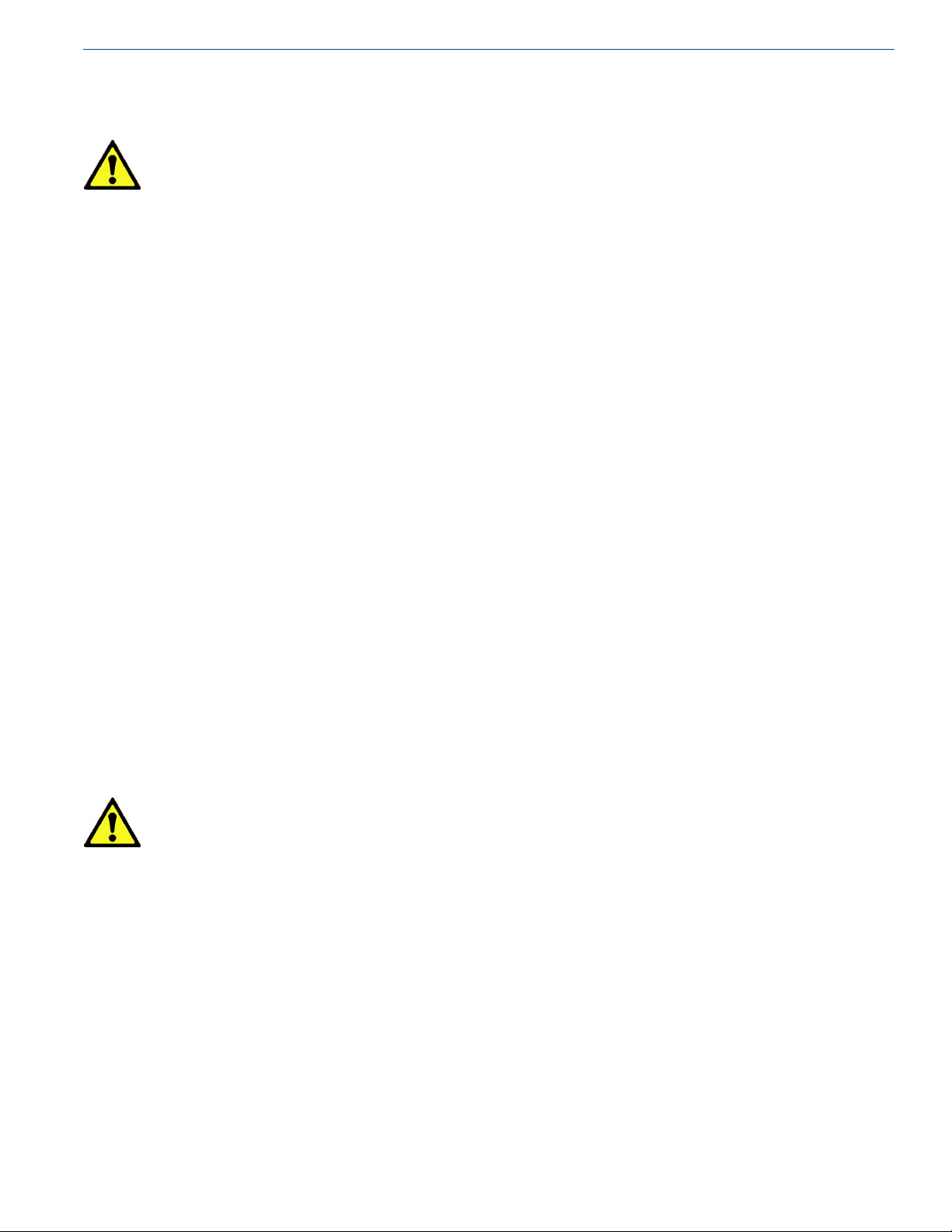
First Time Setup (‘NO TANK SET’
displayed)
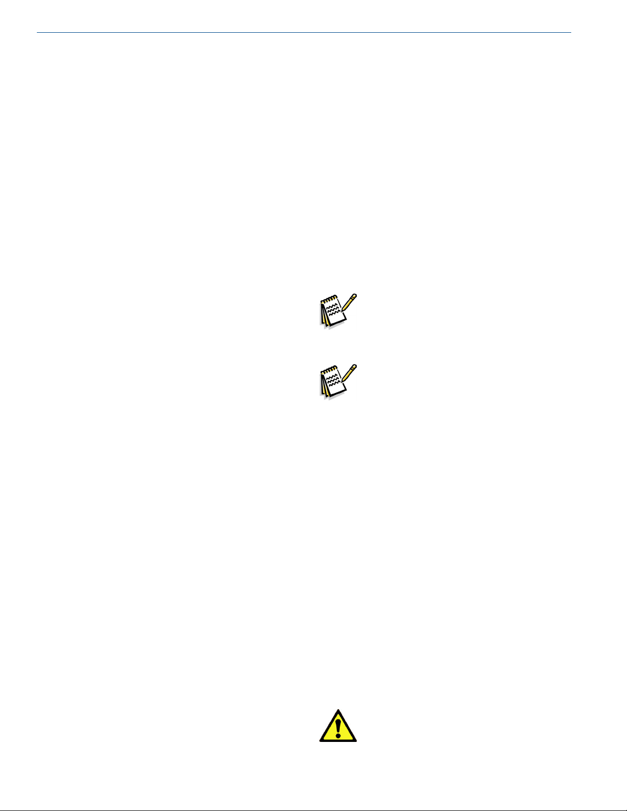
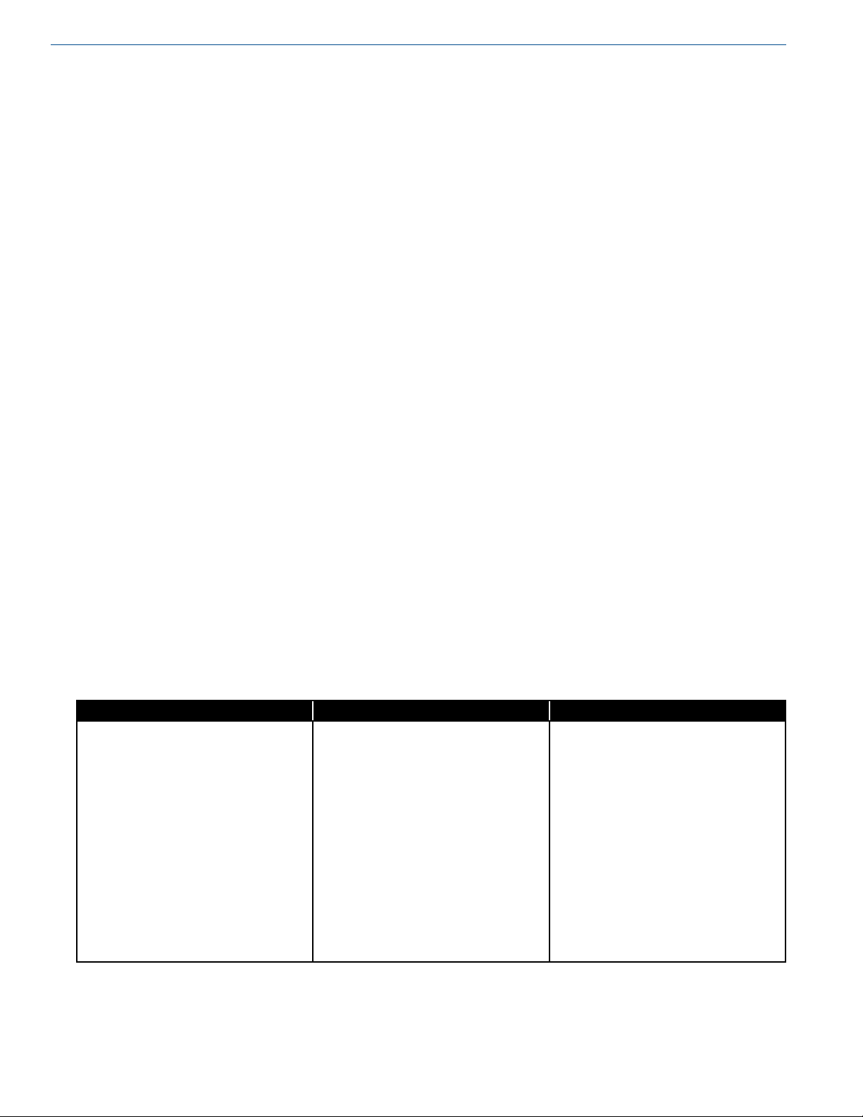
1. Press and release the ‘ON’ button to turn on the gauge
display.
2. Hold the ‘ON’ button for 10-15 seconds to access the
menu. The screen will read “PLEASE WAIT”.
3. Once the ‘ON’ button is held long enough, the “SETUP
STD TANK” screen will ask you to select a standard
tank. Use the up/down arrow buttons to select from the
tank on the tanks list. To set up a custom tank select the
rst tank on this screen as you will need to access the
custom tank menu to change the tank dimensions.
4. With the correct tank highlighted, press the ‘NEXT’
button to select this tank. Press the ‘NEXT’ button again
to move to the next screen.
5. Set the contents of the tank by pressing the up/down
arrow buttons. The options for the contents are Nitrogen
(N2), Oxygen (O2), Argon (Ar), Carbon Dioxide (CO2)
and Nitrous Oxide (N2O). When the correct contents
are highlighted, press the ‘NEXT’ button to move to the
next screen.
6. If the default units of display are “%” you are nished.
You can press the ‘EXIT’ button and can skip to step 10.
7. To read the level in units other than “%” highlight the
“TANK UNITS” option in the menu and press the
‘NEXT’ button.
8. The currently selected units will appear on the left side
of the screen. Use the up/down arrows to change the
units.
9. When the desired units are displayed press the ‘NEXT’
button to proceed.
10. At this point you are done setting up the tank. To exit
press the ‘EXIT’ button. A SETTINGS CHANGED
notication will appear on the left side of the screen.
The unit is asking you if you would like to save the new
settings. Press the ‘SAVE’ button at the bottom of the
screen to save the settings and return you to the main
menu.
11. If you do not need to or have already set the DP zero for
the unit you can skip to step 16.
12. Using the up/down arrow buttons highlight the “DP
ZERO” option on the main menu.
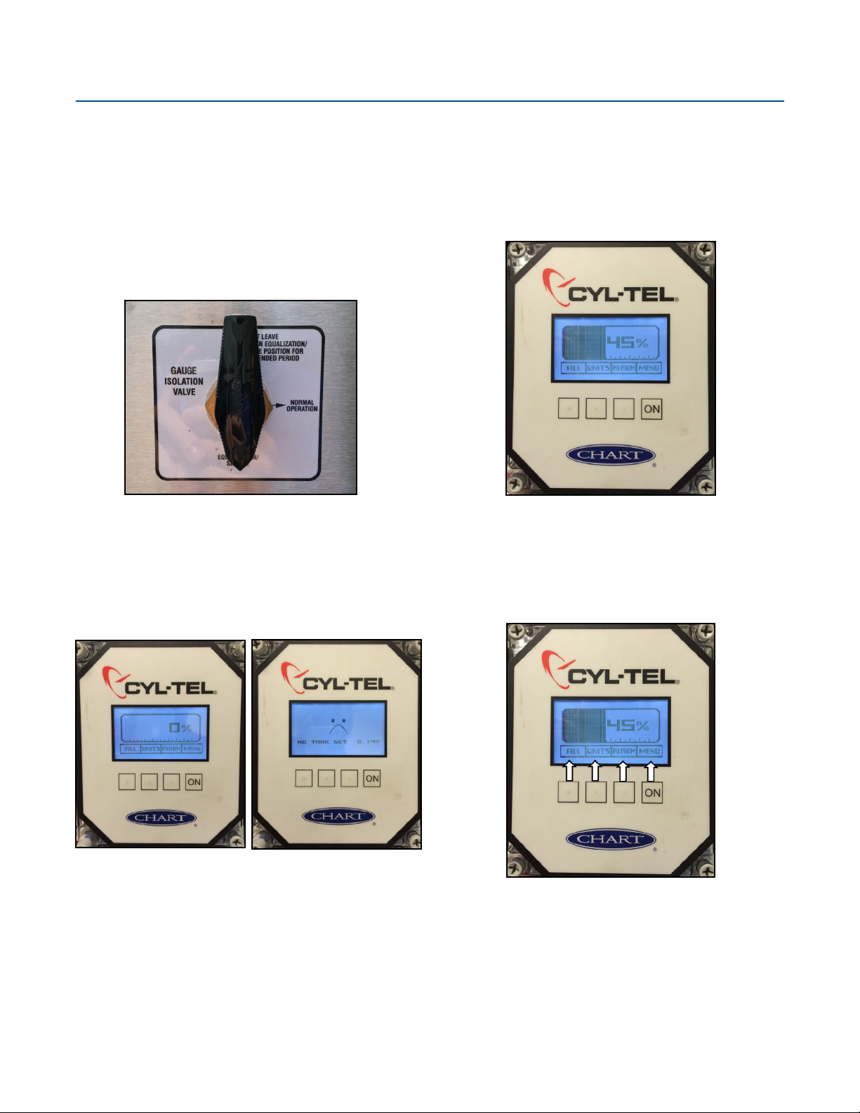
13. Make sure the equalization valve is open or set to
equalization/service.
14. Press the ‘NEXT’ button to display the current DP
ZERO along with the new DP ZERO on the left side of
the screen.
15. Press the ‘NEXT’ button to accept the new DP ZERO.
16. At this point the unit should be fully setup. Press the
‘EXIT’ button to exit to the main display.
17. A SETTINGS CHANGED notication will appear
on the left side of the screen. The unit is asking if you
would like to save the new settings. Press the ‘SAVE’
button on the bottom of the screen.
DP Sensor (selecting correct sensor type)
Note: The gauge can come with a variety of
different sensors depending on the range
needed for the tank. To ensure an accurate
reading the correct sensor must be chosen.
Note: Changing the sensor type also resets the
DP Zero setting. Upon changing the DP
Sensor type remember to follow the DP
Zero procedure.
1. Press and release the ‘ON’ button to turn on the gauge
display.
2. To access the menu hold the ‘ON’ button for 10-15
seconds. The screen will read “PLEASE WAIT”.
3. Once the ‘ON’ button has been held long enough the
MAIN MENU will display with the “SET TANK”
option highlighted.
4. Use the arrow buttons to highlight the “DP SENSOR”
option in the MAIN MENU.
5. Press the ‘NEXT’ button to change the DP SENSOR.
6. Use the arrow buttons to cycle through the DP Sensors.
To determine which DP Sensor to select look for a white
label on either the back or top of the enclosure. Refer to
the table at the end of this guide to help you determine
which DP Sensor you should be using.
7. Once the correct DP Sensor is highlighted press the
‘NEXT’ button to select.
Caution! Any time the DP Sensor is
changed it is suggested that a
new DP Zero is set.