Chassis Plans CPX-15 Use and care manual

CPX-15
CPX-17
CPX-19
Rugged Military Grade
8U Rack Mount
LCD Display
15” XGA TRANSFLECTIVE LCD
17” or 19” SXGA LCD
Technical Reference
22010100B
Revision B
October 8, 2014


Warranty The product is warranted against material and manufacturing defects for two years from
date of delivery. Buyer agrees that if this product proves defective Chassis Plans’ is only
obligated to repair, replace or refund the purchase price of this product at Chassis Plans’
discretion. The warranty is void if the product has been subjected to alteration, neglect,
misuse or abuse; if any repairs have been attempted by anyone other than Chassis Plans;
or if failure is caused by accident, acts of God, or her causes beyond the control of Chassis
Plans. Chassis Plans reserves the right to make changes or improvements in any product
without incurring any obligation to similarly alter products previously purchased.
In no event shall Chassis Plans be liable for any defect in hardware or software or loss or
inadequacy of data of any kind, or for any direct, indirect, incidental or consequential
damages arising out of or in connection with the performance or use of the product or
information provided. Chassis Plans’ liability shall in no event exceed the purchase price
of the product purchased hereunder. The foregoing limitation of liability shall be equally
applicable to any service provided by Chassis Plans.
Return Policy Products returned for repair must be accompanied by a Return Material Authorization
(RMA) number, obtained from Chassis Plans prior to return. Freight on all returned items
must be prepaid by the customer, and the customer is responsible for any loss or damage
caused by common carrier in transit. Items will be returned from Chassis Plans via
Ground, unless prior arrangements are made by the customer for an alternative shipping
method
To obtain an RMA number, call us at 858-571-4330. We will need the following
information:
Return company address and contact
Model name and model # from the label on the back of the display
Serial number from the label on the back of the display
Description of the failure
An RMA number will be issued. Mark the RMA number clearly on the outside of each box,
include a failure report for each board and return the product(s) to our San Diego, CA
facility:
Chassis Plans.
10123 Carroll Canyon Road
San Diego, CA 92131
Attn: Repair Department

Trademarks “The Original Industrial Computer Source”, “Systems Engineered to Perform” and Chassis
Plans are registered trademarks of Chassis Plans, LLC.
IBM, PC/AT, VGA, EGA, OS/2 and PS/2 are trademarks or registered trademarks of
International Business Machines Corp.
Intel is a registered trademark of Intel Corporation.
MS-DOS and Microsoft are registered trademarks of Microsoft Corp.
All other brand and product names may be trademarks or registered trademarks of their
respective companies.
Liability
Disclaimer This manual is as complete and factual as possible at the time of printing; however, the
information in this manual may have been updated since that time. Chassis Plans
reserves the right to change the functions, features or specifications of their products at
any time, without notice.
Copyright © 2014 by Chassis Plans. All rights reserved.
E-mail: Support@chassisplans.com
Web: www.chassisplans.com
Chassis Plans
10123 Carroll Canyon Road • San Diego, CA 92131
Phone: (858) 571-4330 • Fax: (858) 571-6146 • Email: Saleseng@chassisplans.com
CAUT
is inte
n
which
WAR
N
alert t
h
the lit
e
WAR
N
move
WAR
N
the s
u
NOT
E
milita
WA
R
will v
o
WAR
N
groun
d
such
a
nation
by re
m
must
b
ION: The lig
h
n
ded to alert
t
may be of su
N
ING: The e
x
h
e user to th
e
e
rature acco
m
N
ING: If you
a
it without hel
N
ING: Befor
e
u
pplied safet
y
E
: This equip
m
ry environme
R
NING: Chan
g
o
id the syste
m
N
ING: For yo
u
d
ed wall outl
e
a
s the one pr
o
al safety sta
n
m
oving the p
o
b
e located cl
o
h
ting flash wit
h
t
he user to th
f
ficient magn
x
clamation p
o
e
presence o
f
m
panying the
a
re unsure th
p.
e
you connec
t
y
and installat
m
ent is desi
g
nts as per MI
g
es or modifi
c
m
warranty a
n
u
r safety, al
w
e
t. Always u
s
o
vided with t
h
n
dards. This
o
wer cord fro
m
o
se to an eas
h
arrowhead
e presence
o
itude to cons
t
o
int within an
e
f
important o
p
appliance.
at you can lif
t
t
any cables
o
ion instructio
n
g
ned to meet
h
L-STD-810G
c
ations not e
x
n
d could pos
s
w
ays connect
s
e a power c
o
h
e equipment
equipment c
a
m
the power
o
ily accessibl
e
symbol insid
e
o
f uninsulated
t
itute a risk o
f
equilateral tri
p
erating and
s
f
t the equipm
e
o
r install the
C
n
s.
harsh enviro
n
G
, MIL STD-4
6
x
pressly app
r
s
ibly damage
equipment t
o
o
rd with a pro
t
, or one in c
o
a
n be discon
n
o
utlet. This
m
e
power outle
t
e
an equilate
r
, dangerous
v
f
electric sho
c
angle is inte
n
s
ervicing inst
r
e
nt safely, no
C
PX monitor,
n
mental cond
6
1F and DO-
1
r
oved by Cha
s
the equipme
o
a three-pro
n
perly ground
e
o
mpliance wit
h
n
ected from t
h
m
eans the eq
u
t
r
al triangle
v
oltage
c
k
n
ded to
r
uctions in
not try to
refer to
itions of
1
60F
s
sis Plans
nt.
n
g,
e
d plug,
h
your
h
e power
u
ipment

Chassis Plans CPX-15, -17, -19 Technical Reference Index
Table of Contents
Chapter1‐Introduction_______________________________________________________________1
Description_______________________________________________________________________________1
Table1–DisplaySpecifications____________________________________________________________________1
CPXPartNumberMatrix_____________________________________________________________________2
Table2–CPXPartNumberMatrix_________________________________________________________________2
LCDEnhancements_________________________________________________________________________3
Figure1–EMIShieldingEffectivenessofITOCoating__________________________________________________3
Figure2–OpticalStackonLCD____________________________________________________________________3
Figure3–ComparisonofReflectionswithandwithoutOpticalBonding___________________________________4
Figure4–ComparisonwithandwithoutOpticalBonding_______________________________________________4
GenesisBasedLCDControllers________________________________________________________________5
Photos___________________________________________________________________________________5
FrontView____________________________________________________________________________________5
RearPanelI/O–StandardController_______________________________________________________________5
RearPanelI/O–AdvancedController_______________________________________________________________5
Specifications______________________________________________________________________________6
Enclosure________________________________________________________________________________________6
15”Display______________________________________________________________________________________6
17”Display______________________________________________________________________________________6
19”Display______________________________________________________________________________________6
PowerSupplyOptions______________________________________________________________________________6
DisplayEnhancementOptions_______________________________________________________________________6
Table3–Specifications__________________________________________________________________________6
Environmental____________________________________________________________________________________7
Table4–EnvironmentalSpecifications______________________________________________________________7
StandardControllerDVI‐D/VGAInputFeatures:_________________________________________________________8
AdvancedControllerMulti‐InputFeatures:_____________________________________________________________8
Table5–LCDControllersSpecifications_____________________________________________________________8
Figure5‐CPXOutlineDrawing____________________________________________________________________9
Chapter2–PowerSupplyOptions______________________________________________________10
ACInputPowerSupply_____________________________________________________________________10
Table6‐ACInputSupplySpecifications____________________________________________________________10
Photo1‐ACPowerSupply______________________________________________________________________10
12VDCInputTransientFilter________________________________________________________________11
Connectors_____________________________________________________________________________________11
MIL‐STD‐704/1275DCInputConverter________________________________________________________12
OperatingSpecifications___________________________________________________________________________12
Connectors_____________________________________________________________________________________12
EnvironmentalSpecifications_______________________________________________________________________12
Table7‐MIL‐STD‐704PowerSupplySpecifications___________________________________________________12
+/‐48VDCPowerSupply____________________________________________________________________13
OperatingSpecifications___________________________________________________________________________13
Connectors_____________________________________________________________________________________13
ElectricalSpecifications____________________________________________________________________________13
Table8‐48VDCPowerSupplySpecifications________________________________________________________13

Chassis Plans CPX-15, -17, -19 Technical Reference Index
Chapter3–Installation_______________________________________________________________14
ProductContents__________________________________________________________________________14
RackInstallation__________________________________________________________________________14
Figure6‐RackMountingHoleSpacing_____________________________________________________________14
ConnectingtheDisplay_____________________________________________________________________15
StandardControllerRearPanelConnections___________________________________________________15
Figure7‐StandardControllerRearPanelI/O________________________________________________________15
Table9‐RearPanelConnections–StandardController_______________________________________________15
AdvancedControllerRearPanelConnections___________________________________________________16
Figure8‐AdvancedControllerRearPanelI/O_______________________________________________________17
Table10‐RearPanelConnections–AdvancedController______________________________________________17
Chapter4–Operation________________________________________________________________18
LCDFrontPanelControls___________________________________________________________________18
Table11‐FrontPanelControls___________________________________________________________________18
StandardControllerOSDMenus_____________________________________________________________19
Table12‐StandardControllerOSDMenus__________________________________________________________20
AdvancedControllerOSDMenus_____________________________________________________________21
AppendixA–DisplaySerialControlProgramming_______________________________________25
RS‐232Serialcontrol_______________________________________________________________________25
StandardControllerSerialControlFunctions___________________________________________________25
Table13‐StandardControllerCommandstoImplementSwitchMountControlButtons_____________________25
Table14‐StandardControllerParameterSetting‐Immediate,Relative,ResetandQuery____________________26
Table15‐StandardControllerOtherControl________________________________________________________28
AdvancedControllerSerialControlFunctions___________________________________________________29
Table16‐AdvancedControllerCommandstoImplementSwitchMountControlButtons____________________29
Table17‐AdvancedControllerParameterSetting‐Immediate,Relative,ResetandQuery___________________29
Table18‐AdvancedControllerOtherControl_______________________________________________________38
Table19‐HextoASCIIConversionTable___________________________________________________________40
AppendixB–AutoColorGain__________________________________________________________41
ImageB‐1–AutoColorGainExample______________________________________________________________41
AppendixC–DVI‐DversusDVI‐IConnectors______________________________________________42
Overview________________________________________________________________________________42
Connectors_______________________________________________________________________________42
AppendixD–EthernetNetworkConnection______________________________________________43
ConnectinganetworkporttoCPXFamily______________________________________________________43
GettheIPaddressusingDHCP_______________________________________________________________44
WebConsole_____________________________________________________________________________44
IPLocator________________________________________________________________________________44
ImageD‐1–IPLocatorScreenShot________________________________________________________________44

Chassis Plans CPX-15, -17, -19 Technical Reference Index
Networkconfiguration_____________________________________________________________________44
ImageD‐2–NetworkDropDown_________________________________________________________________44
ImageD‐3–NetworkConfigureSettings___________________________________________________________45
ConnecttoasingleCPXFamily_______________________________________________________________45
TableD‐1–RemoteControl______________________________________________________________________45
ImageD‐4–IPAddressLocator___________________________________________________________________46
ImageD‐5–IPAddressSettingandEnable__________________________________________________________46
ConnecttomultipleCPXFamily______________________________________________________________46
TableD‐2–RemoteControl______________________________________________________________________46
ImageD‐6–DHCPTableScreenshot_______________________________________________________________47
ImageD‐7–NATFowardingScreenshot____________________________________________________________47

Chassis Plans CPX-15, -17, -19 Technical Reference Index
This Page Intentionally Blank
Chassis Plans CPX-15, -17, -19 Technical Reference Chapter 1 - Introduction
Page 1
Chapter 1 - Introduction
Description
The military grade CPX family – comprised of 8U TFT LCD’s, offer rugged military rack mount or panel mount
LCD displays. Whether seeking a 15”, 17” or 19” display, these military touch screen monitors are designed to
perform and engineered to last. Meeting military standards 901D and 810G, the CPX family’s 5052-H32
aluminum construction and locking stainless steel hardware are inherently rugged and reliable. All electrical
components are selected for strength, integrity, and reliable operation. Rack mount ears are securely screwed to
the sides of the display body and can be removed, allowing the monitor to be used with a VESA mount, panel
mount or bulkhead mount.
The 17” and 19” displays are high performance, long life TFT LCD’s offering a maximum native resolution of
1280x1024. The displays offer optional optically bonded 3mm Dura Block 90 anti-reflective overlay glass. In
addition, an optional laminated 1.1mm soda lime glass with an ITO conductive EMI filter and an additional
1.1mm soda lime glass overlay with Dura Block 90 anti-reflective (AR) coating. Both glass components are
optically bonded to each other, and to the front of the display, for superior viewing clarity and overall
ruggedness. A 3mm copper bus bar surrounds the entire glass stack-up and provides consistent grounding. A
contrast ratio of approximately 1300:1 is delivered with this ITO/Anti-Reflective glass stack-up.
The 15-inch display offers 1024x768 resolution, transflective TFT technology and an LED backlight and is
intended for high bright installations such as outdoors. The other two models offer either 17-inch or 19-inch
LCDs with LED backlights. All other features of the systems are identical including dimensions, input signal
options and LCD controllers.
CPX-15 15” LCD CPX-17 17” LCD CPX-19 19” LCD
Contrast Ratio 1000:1 1000:1 1000:1
Viewing Angle (L/R/U/D) 80º 80º 80º
Response Time 17ms 30ms 5ms
Brightness 950 cd/m
2
350 cd/m
2
350 cd/m
2
Backlight LED LED LED
Native Resolution 1024 x 768 1280 x 1024 1280 x 1024
Aspect Ratio 4:3 5:4 5:4
Table 1 – Display Specifications
Dura Block 90 is a two surface treatment. The front surface is an oleophobic anti-reflective coating resistant to
fingerprints. The inner surface is treated with an infrared resistant coating to reduce heat loading on the LCD
display from exposure to sunlight.
The displays offer 16.7 million colors (True Color). The displays provide multiple signal input options including
aRGB, DVI-D, DVI-I, NTSC, S-Video and Composite Video, depending on the controller.
The displays offer a choice of high quality advanced scaling controllers with a Genesis chipset. The Standard
Controller offers DVI-D and VGA (aRGB) inputs. The Advanced Controller offers DVI-D, VGA (aRGB), HDMI,
NTSC, S-Video and CVS with an option for Component (YCbCr) input. In addition, the Advanced Controller
supports Picture-In-Picture (PIP) and Picture-By-Picture. These are specifically ruggedized controllers offering
as standard conformal coating with high shock/vibration and temperature extreme tolerances as well as long life
product availability for assured delivery throughout multi-year programs.
As with all Chassis Plans products, a wide variety of custom options can be configured per customer or
application specific requirements. Contact your Sales Engineer to discuss your particular requirements.

Chassis Plans CPX-15, -17, -19 Technical Reference Chapter 1 - Introduction
Page 2
CPX Part Number Matrix
Product Family Head Unit Controller Option Power Input
CPX1 = CP Panel Extreme
151A = 15” LCD with EMI Shield A1 = Advanced
Controller
A = AC 110V
151B = 15” LCD C1 = Standard
Controller
B = 12VDC
151C = 15” LCD with 3mm cover
glass
C = 28VDC
151E = 15” LDC with USB Rhino
Touch, Touch Screen
D = 48VDC
171A = 17” LCD with EMI Shield
171B = 17” LCD
171C = 17” LCD with 3mm cover
glass
171E = 17” LDC with USB Rhino
Touch, Touch Screen
191A = 19” LCD with EMI Shield
191B = 19” LCD
191C = 19” LCD with 3mm cover
glass
191E = 19” LDC with USB Rhino
Touch, Touch Screen
Table 2 – CPX Part Number Matrix
Part Number Scheme CPX1-XXXXXX-A
Example: CPX1 -171CA1-A
CPX1 = CP Panel Extreme
171C = 17” LCD with 3mm cover glass
A1 = Advanced Controller
A = AC 110V
Chassis Plans CPX-15, -17, -19 Technical Reference Chapter 1 - Introduction
Page 3
LCD Enhancements
Chassis Plans starts with Grade A Industrial Quality LCD panels selected for optical performance, high reliability
and long product life cycle. In order to not only ruggedize the LCD, but to also enhance the mechanical, optical
and EMI properties of the finished unit, as an option, Chassis Plans optically bonds one 3mm AR or two layers
of coated 1.1 mm soda-lime float glass to the front of the LCD panel. The first layer is coated with an Indium Tin
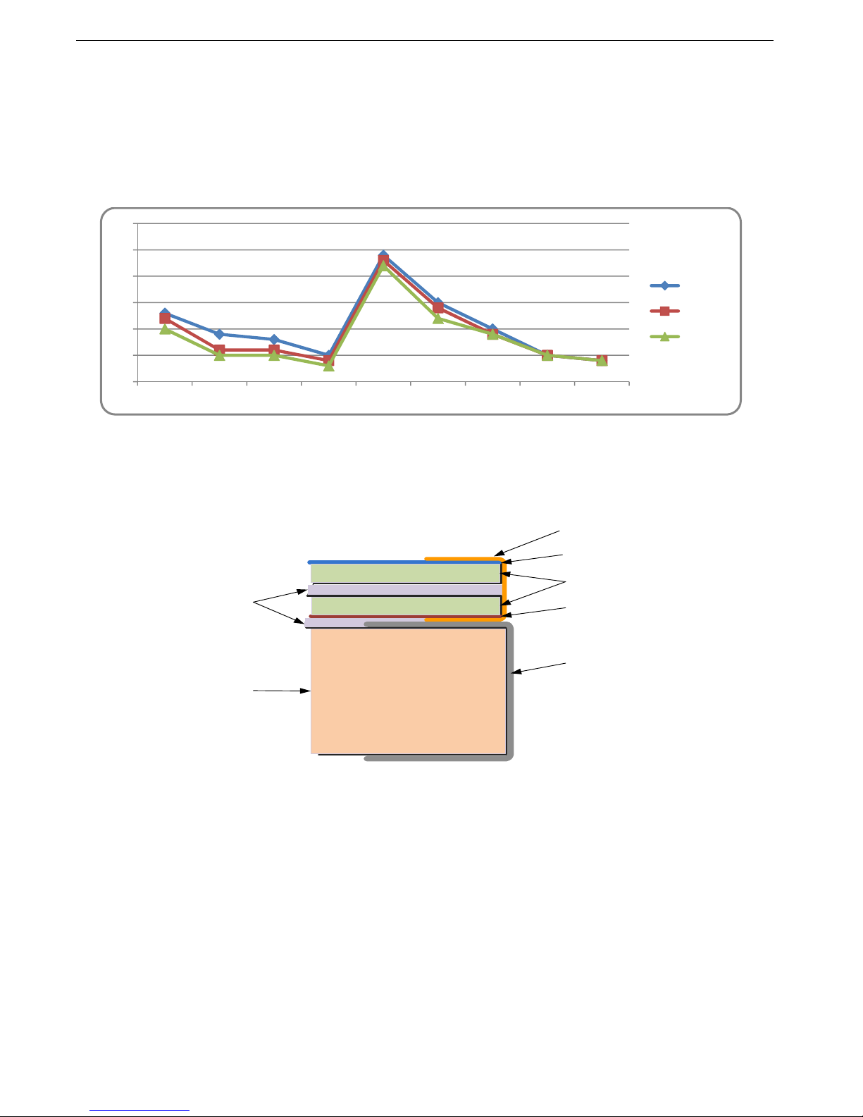
Oxide (ITO) coating with a surface resistivity of <13.5 ohms/sq. See Figure 1 for attenuation values.
Figure 1 – EMI Shielding Effectiveness of ITO Coating
There is a Copper conductive buss bar that wraps around the edge of the glass to facilitate conduction from the
ITO coating to the front surface of the laminated structure to make a complete electrical shield around the face of
the LCD. See Figure 2 for details.
Figure 2 – Optical Stack on LCD
The second layer of glass is coated with a Dura Block 90 Oleophobic Anti-Reflective (AR) coating which
matches the index of refraction of air to eliminate surface reflections. These layers of coated glass are bonded
together with an index matching optical adhesive to eliminate internal reflections caused by the index of
refraction mismatch between the soda lime glass and air. This eliminates over 95% of unwanted glare from the
screen. Please see Figure 3 below for more details.
20
25
30
35
40
45
50
30MHz 75MHz 100MHz 150MHz 200MHz 300MHz 500MHz 700MHz 1000MHz
15"LCD
17"LCD
19"LCD
AR Coating
ITO Coating
Soda Lime Float Glass
Copper Buss Bar
LCD Frame
O ptical Index
Matching
Adhesive
LCD Panel
And
Backlight

C
T
a
d
r
e
a
d
a
c
p
r
f
o
c
o
B
h
i
t
h
b
y
P
h
G
D
C
hassis Plan
s
he resulting
s
d
hesive used
e
mains pliabl
e
d
ditional laye
c
tually occur
r
events any
c
o
gging of the
d
o
nduction pa
t
y eliminating
i
gh bright sit
u
h
e reflected li
g
y
the backlig
h
h
oto Courtesy of
D
S Clearview
4.5
%
4.5
%
4.5
%
4.5
%
4.5
%
Witho
O
s
CPX-15, -1
7
Figure 3
s
tructure has
is a silicone
e
and therefo
rs of glass p
r
the shards o
f
c
ondensation
d
isplay. Fin
a
t
h to help dis
s
the majority
o
u
ations. An al
t
g
ht. The dow
n
h
ts.
F
i
Refle
Lig
To
t
22.
5
%
%
%
%
%
ut Optical Bond
i
O
r AR Coating
7
, -19 Techni
c
– Comparis
o
greatly enha
n
RTV and off
e
r
e acts as a
s
r
ovides a ver
y
f
glass will be
from buildin
g
a
lly, the adde
d
s
ipate the he
a
o
f reflected li
g
t
ernative to i
m
n
side to this
a
i
gure 4 – Co
m
cted
ht
t
al
5
%
i
ng
c
al Referenc
e
P
o
n of Reflec
t
n
ced optical
c
e
rs other ben
e
s
hock absorb
i
y
rugged com
retained tog
e
g
up in the air
d
mass bond
e
a
t generated
g
ht, the appa
r
m
proving the
c
a
pproach is t
h
m
parison wi
e
P
age 4
t
ions with a
n
c
haracteristic
s
e
fits mechani
i
ng medium f
o
posite struct
u
e
ther to prev
e
gap betwee
n
e
d to the fron
t
in the backlig
r
ent contrast
c
ontrast is to
h
e higher po
w
th and with
o
n
d without O
s
in high am
b
cally to the L
C
o
r the front o
f
u
re. Another
e
nt injury to
p
n
the layers o
f
t
of the LCD
d
g
hts themselv
improves m
a
increase the
w
er requirem
e
o
ut Optical
B
0.3%
With
An
0.1%
0.1%
0.1%
0.1%
Ch
ptical Bondi
b
ient light con
CD as well.
T
f
the LCD. T
o
benefit is tha
p
ersonnel. T
h
f
glass which
d
isplay adds
v
es.
a
king the disp
back light le
v
e
nts and hig
h
B
onding
Reflected
Light
Total
0.7%
Optical Bondin
g
d AR Coatin
g
apter 1 - Intr
o
ng
ditions. The
T
he adhesiv
e
o
gether with
t
t should bre
a
h
e adhesive
a
would caus
e
a thermal
lay more rea
d
v
els to overp
o
h
er heat gene
g
o
duction
optical
e
t
he
a
kage
a
lso
e
d
able in
o
wer
rated
Chassis Plans CPX-15, -17, -19 Technical Reference Chapter 1 - Introduction
Page 5
Genesis Based LCD Controllers
The LCD Controller is a key component in any display system and no expense has been spared in specifying
the Standard Controller and Advanced Controller Genesis controllers. These are long life revision controlled
military grade components. The Genesis chip set is the current gold standard for LCD controllers. The
controllers support 3x8-bit 16.7 million colors at up to 1600x1200 (Advanced Controller) scaled to 1280x1024
native panel resolution. Refresh rates of 60Hz for UXGA and SXGA with higher refresh rates for lower
resolutions available. Computer input signals of VGA, SVGA, XGA, SXGA, WXGA and UXGA are supported.
Video inputs of NTSC, PAL and SECAM are optionally available. DVI inputs supports up to 1600x1200 60Hz
signals. These ruggedized military grade controllers are rated for operating at -40 to +80 deg C, use low mass
tantalum capacitors for maximum vibration and shock tolerance and are conformal coated for extreme
ruggedness. The coating is silicone resin conformal coating.(MOD) DEF-STAN 59/47 Issue 4 &UL QMJU2
compliant
MTBF for the controllers is in excess of 150,000 to 200,000 hours.
The Standard Controller provides up scaling while the Advanced Controller provides up and down scaling. This
allows input scaling of virtually any input signal to scale the image to the 1280x1024 native LCD panel
resolution. They provide for PC, Apple and Sun input resolutions.
The Standard Controller and Advanced Controller provide DVI-D inputs.
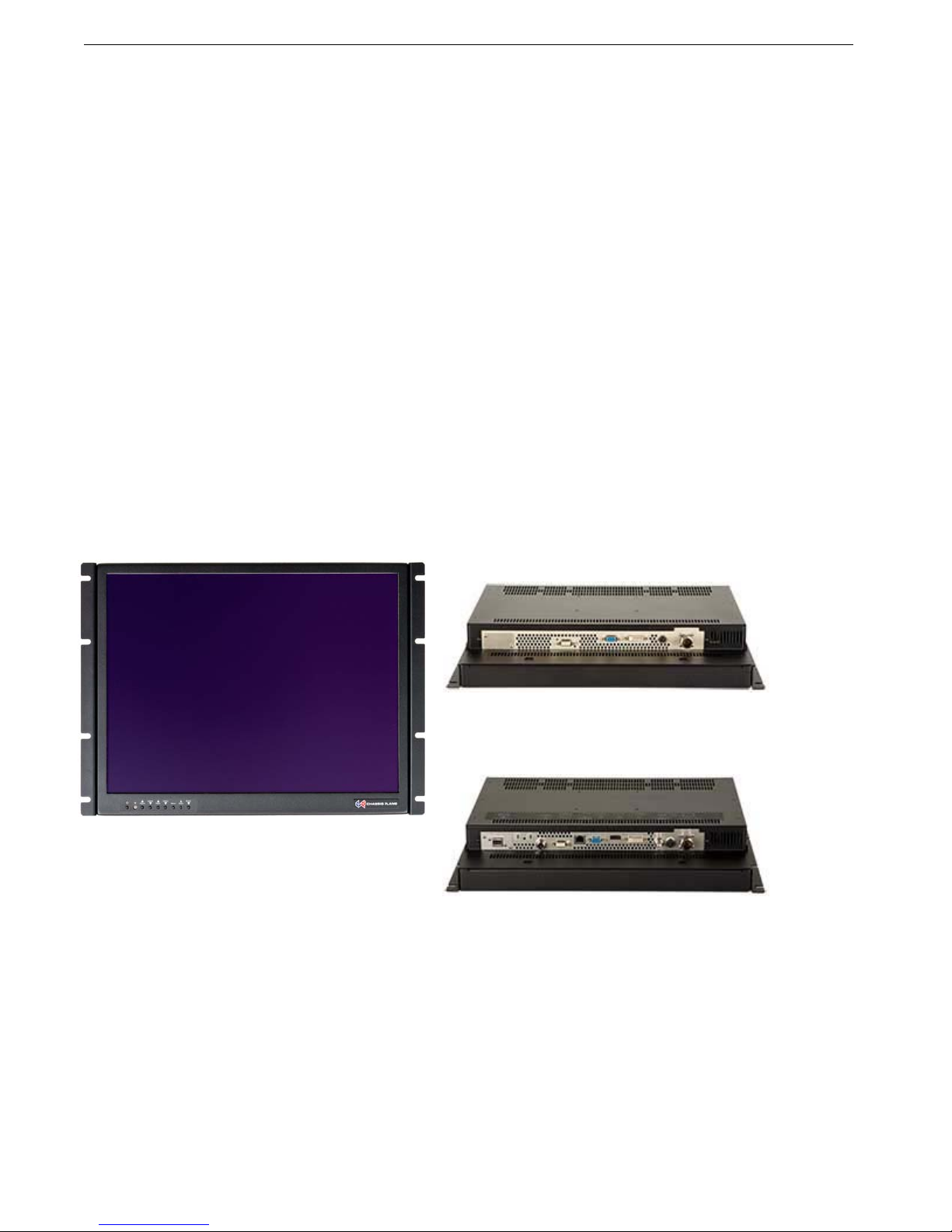
Photos
Front View
Rear Panel I/O – Standard Controller
Rear Panel I/O – Advanced Controller

Chassis Plans CPX-15, -17, -19 Technical Reference Chapter 1 - Introduction
Page 6
Specifications
Enclosure
8U (13.97”) x 3.2” deep
Construction: 5052 aluminum alloy
All stainless steel hardware
All self-locking pressed in fasteners where
appropriate
Powder coat black, medium texture, for ruggedness
Other colors optionally available
Designed to Mil-Spec Standards to Satisfy Military,
Industrial and Commercial Requirements
Compact Enclosure for Limited Depth Installation
Weight: 19.5-20.5lbs (depending on model &
features)
15” Display
17" TFT LCD 1024x768
Display Colors: 16.7 Million
Response Time: 17ms Typical
Viewing Angle: 80 deg
Contrast Ratio: 1000:1 typical native
Brightness: 950cd/m2 typical
Pixel Pitch: 0.264mm x 0.264mm
Pixel Arrangement: R.G.B Stripe
Operating Temperature: -30 to + 70 Deg C
Storage Temperature: -40 to +80 Deg C
17” Display
17" TFT LCD 1280x1024
Display Colors: 16.7 Million
Response Time: 30ms Typical
Viewing Angle: 80 deg
Contrast Ratio: 1000:1 typical native
Brightness: 350cd/m2 typical
Pixel Pitch: 0.264mm x 0.264mm
Pixel Arrangement: R.G.B Stripe
Operating Temperature: -20 to + 70 Deg C
Storage Temperature: -30 to +80 Deg C
19” Display
19" TFT LCD 1280x1024
Display Colors: 16.7 Million
Response Time: 5ms
Viewing Angle: 80 deg
Contrast Ratio: 1000:1 typical native
Brightness: 350cd/m2 typical
Pixel Pitch: 0.297mm x 0.297mm
Pixel Arrangement: R.G.B. Stripe
Operating Temperature: 0 to + 50 Deg C
Storage Temperature: -20 to +60 Deg C
Power Supply Options
AC Input
100 to 260VAC, auto selecting
47-66 HZ
12VDC Input Transient Filter
Line transient protection for 12VDC vehicular
applications
Mil-Std-1275A DC/DC Converter
True 1275 compliance for military 28VDC
nominal vehicle inputs
18 to 36VDC input
48VDC DC/DC Converter
36 to 75VDC Input
Isolated Inputs for +/- input levels
See the appropriate power supply section for complete
power supply specifications.
Display Enhancement Options
Using 3mm smudge-resistant AR coated soda lime
float glass, bonded to the LCD panel with optical
index matched adhesive
Using a laminate of 1.1mm smudge-resistant AR
coated soda lime float glass panel and a 1.1 mm
ITO coated glass panel(<12.5Ω/sq) grounded via a
copper buss bar, bonded to the LCD panel with
optical index matched adhesive
Table 3 – Specifications

Chassis Plans CPX-15, -17, -19 Technical Reference Chapter 1 - Introduction
Page 7
Environmental
Designed to meet or exceed MIL-STD-810G to the below specifications.
ALTITUDE
10,000 ft. Operational,
30,000 ft. Storage
MIL-STD-810, Method 500.5
HIGH TEMPERATURE
70°C Operational, 80°C Storage
MIL-STD-810, Method 501.5
LOW TEMPERATURE
-20°C Operational, -30°C Storage
MIL-STD-810, Method 502.5
HUMIDITY
5-95%, Non-condensing
MIL-STD-810, Method 507.5
BLOWING SAND AND DUST
Procedures I and II
MIL-STD-810, Method 510.5
TRANSPORT VIBRATION
US Highway Truck and Air Transport
MIL-STD-810, Method 514.6
BENCH HANDLING SHOCK
Procedure VI, 20G @ 11ms
MIL-STD-810, Method 516.6
Table 4 – Environmental Specifications

Chassis Plans CPX-15, -17, -19 Technical Reference Chapter 1 - Introduction
Page 8
Standard Controller DVI-D/VGA Input Features:
Inputs:
Analog RGB: 60Hz at SXGA, WXGA, XGA,
SVGA, VGA
With auto detect of Digital
Separate Sync, Sync-On-Green &
Composite Sync. Auto detects
VGA ~SXGA interlaced &
noninterlaced.
DVI-D: 60Hz at SXGA, WXGA, XGA,
SVGA, VGA
Image Scaling: Up scaling to fit input to panel
resolution.
Image Control: Brightness, Contrast, Saturation,
Hue, Frequency, Phase, Color
temperature, Image position, Hue,
Gamma.
Other Features: Auto picture setup, Auto RGB cali-
bration, Auto source seek, OSD
timeout, OSD position, Input
source select, OSD menu lock,
Direct key for brightness level
adjustment.
Advanced Controller Multi- Input Features:
Inputs:
Analog RGB: 60Hz @ UXGA
75Hz @ SXGA, WXGA, SVGA, VGA
1152 x 900 @ 66Hz (SUN)
1152 x 900 @ 76Hz (SUN)
1280 x 1024 @ 76Hz (SUN)
With auto detect of Digital Separate
Sync, Sync-On-Green & Composite
Sync. Auto detects VGA ~UXGA
interlaced & non-interlaced.
DVI-D: 60Hz @ WUXGA
60Hz @ UXGA
75Hz @ SXGA, WXGA, XGA,
SVGA, VGA
HDMI: 60Hz @ WUXGA
60Hz @ UXGA
75Hz @ SXGA, WXGA, XGA,
SVGA, VGA
Video: NTSC / PAL / SECAM (Interlaced)
Composite Video
HD Component YPbPr
SD Component YCbCr
RGB Video SD Component (YCbCr)
(Optional)
Features: Image Up-Scaling
Image Down-Scaling
Picture In Picture
Picture By Picture
Memory Buffer
Sync On Green/Composite
DV RS-232 Serial Protocol
Ethernet Command Protocol
Text Overlay Function
Variable Aspect
Freeze & Zoom Function
Programmable Hot Keys
Image Control: Auto configuration, Brightness,
Contrast, Clock, Phase, Color
temperature, Image position,
Saturation, Hue, Gamma.
Other Features: System Information, OSD position,
Scaling to fill screen and fill to aspect
ratio, OSD timeout, Factory reset,
OSD menu transparency, Horizontal
& Vertical image inversion, Picture in
Picture.
Table 5 – LCD Controllers Specifications

Chassis Plans CPX-15, -17, -19 Technical Reference Chapter 1 - Introduction
Page 9
Figure 5 - CPX Outline Drawing

C
A
T
ci
p
r
A
I
O
S
Chassis Pla
n
C
hapter
A
C Input
P
he AC Input
P
rcular mil co
n
r
ovided to se
c
A
lternate AC
s
I
NPUT
Voltage
Current
Frequency
Input Conn
e
O
UTPUT
Total Regul
Set Point A
c
Hold-up Ti
m
Over Volta
g
Over Curre
n
Short Circu
S
IZE
L X W X H
Weight
n
s CPX-15, -1
2 – Po
w
P
ower S
u
P
ower Suppl
y
n
nector for c
o
c
urely mount
s
upplies are
a
e
ctor
ation
c
curacy
m
e
g
e Protection
n
t Protection
it Protection
7, -19 Techn
w
er Sup
p
u
pply
y
is a 65W M
e
o
nnecting to t
h
the supply in
a
vailable as r
e
100-240VA
C
2.0A @ 10
0
50-60Hz
3-Pin IEC 3
2
< +/- 5%
< +/- 3% @
>12mS @
F
115VAC
Built-in
Built-in
Pulsing mo
d
recovery
5.07” X 3.0
6
1.2 lbs
Tabl
e
ical Referen
c
P
p
ly Opti
o
e
dical Grade
h
e CPX. Th
e
a rack.
e
quired by th
e
C
0
VAC
2
0 Receptacl
60% Load
F
ull Load,
d
e, auto
6
” X 1.35”
e
6 -
A
C Inpu
t
Photo 1 -
A
c
e
P
age 10
o
ns
“Brick” style
p
e
input accep
t
e
application
o
e
ENVI
R
Op
e
Sto
r
SAF
E
c
T
UL
6
CS
A
CB
p
CE
m
Cla
s
EMI/
E
Emi
s
Im
m
t
Supply Sp
e
A
C Power Su
C
p
ower supply
t
s a standard
o
r environm
e
R
ONMENTA
L
e
rating Temp
e
r
age Temper
a
E
TY
T
UVus
6
0601-1
A
C22.2 No.
6
p
er IEC 6060
m
arked to L
V
s
s I
E
MC
s
sions
m
unity
e
cifications
u
pply
C
hapter 2 – P
o
. The output
IEC 320 plu
g
e
ntal require
m
L
e
rature
a
ture
6
01.1-M90
0
1-1
V
D
CISPR11 an
EN61000-3-
2
EN61000-4-
2
o
wer Supply
is provided
w
g
.
A
bracket
i
m
ents.
0 to
5
-40 t
o
d FCC Part 1
2
, -3
2
, -3, -4, -5, -
6
Options
w
ith a
i
s
5
0°C
o
+85°C
5, Class B
6
, -9, -11

Chassis Plans CPX-15, -17, -19 Technical Reference Chapter 2 – Power Supply Options
Page 11
12VDC Input Transient Filter
The CPX family display consoles require nominal +12VDC at 40W for operation. An EMI line filter is provided to
limit EMI emissions and to provide a small measure of input filtering.
For operation from unregulated 12VDC (+/-10%) such as in a vehicular or marine environment, front end
transient filtering is required to suppress potentially damaging spikes from large inductive loads in the DC circuit
(starters, etc.).
The xxx 12VDC Input Transient Filter provides an input Transient Protection as well as inductive and capacitive
filtering to suppress large input transients. A bridge rectifier provides reverse connection protection. A circuit
breaker provides for failure protection and allows the power to be disconnected.
Connectors
Input Connector MS3102A-10SL-3P (MIL-C-5015)
Mating Input Connector MS3106A-10SL-3S (Straight)
MS3108A-10SL-3S (Right Angle)
Pinouts Pin A – Positive
Pin B – Negative Input
Pin C – N/C
Output Connector MS3102A-10SL-3S (MIL-C-5015)
Mating Output Connector MS3106A-10SL-3S (Straight)
MS3108A-10SL-3S (Right Angle)
Pinouts Pin A – Positive
Pin B – Negative
Pin C – N/C
This manual suits for next models
2
Table of contents
Other Chassis Plans Monitor manuals


