S&S Northern Merlin CO2 AVG Operational manual

Merlin CO2 Monitor Product Data Sheet
S&S Northern Ltd 1
Gas Safety Products
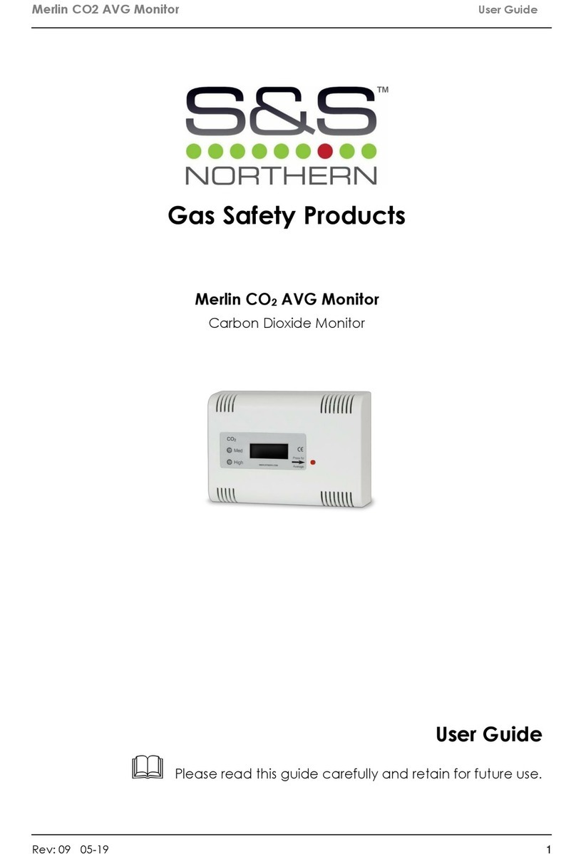
Merlin CO2 AVG Monitor
Read these instructions carefully before operating or servicing.
Installation, operating and maintenance

Merlin CO2 Monitor Product Data Sheet
S&S Northern Ltd 2
The unit should be installed by a competent person only.
The expected life time of the detector/sensor element is: 10 Years
The unit should be stored in cool, dry conditions.
We do recommend that this product is serviced annually.
If the unit is found to be damaged –Contact us.
Table of contents
1General information ..........................................................................................3
2Features.............................................................................................................3
3Installation .........................................................................................................3
3.1 Mounting the CO2 Sensor. .............................................................................................3
3.2 Mains Supply...................................................................................................................3
3.3 Alarm Relay.....................................................................................................................3
3.4 Pre Alarm Relay..............................................................................................................3
4Operation Instructions......................................................................................3
4.1 How to turn the system on and off..................................................................................3
4.2 Explanation of LED status...............................................................................................3
4.2.1Moderate (Amber) LED...................................................................................................3
4.2.2 Poor (Red) LED ..............................................................................................................3
4.3 Explanation of CO2 Average Button Facility...................................................................4
Merlin CO2 Wiring Diagram......................................................................................5

Merlin CO2 Monitor Product Data Sheet
S&S Northern Ltd 3
1 General information
The Merlin CO2 AVG Monitor has an LCD display to show the user a clear and precise
reading of the CO2 level in the room and average CO2 level over the past 24 & 8 hours. The
monitor also provides statistics for the highest reading over the past 24 hours along with a
traffic light colour system indicating the air quality in the area.
2 Features
Clear digital readings of the live CO2 levels.
LED warning lights when the CO2 levels increase.
Push button on the fascia to display the 24 hr CO2 average, which is updated every 10
minutes along with the previous 8-hour average and highest CO2 level within the last 24hrs.
240v AC Main Powered.
Terminal outputs to control mechanical air ventilation.
Complies with the Scottish Technical Handbook October 2015 requirements for CO2
monitoring with domestic dwellings
2 Year Warranty
Made in Britain
3 Installation
3.1 Mounting the CO2 Sensor The control panel is designed for surface mounting using
2 mounting screws. Removing the back plate gives access to the circuit board. Do not attempt
to remove the PCB.
3.2 Mains Supply A 230-volt electrical supply should be supplied to the panel. This should be
externally fused at 3 Amps using a fused spur and should be connected to the terminals marked ‘LN
Power’.
3.3 Alarm Relay This will switch over should the level of CO2 rise above 700ppm, and
automatically switch back once the levels have dropped below 650ppm.
3.4 Pre Alarm Relay This will switch over should the level of CO2 rise above 1000ppm, and
automatically switch back once the levels have dropped below 950ppm.
4 Operation Instructions
4.1 How to turn the system on and off
1. To turn on the Merlin CO2 AVG monitor you need to supply 230V into the “L & N POWER”
terminal, this will then illuminate the blue LCD screen and initiate a 60-second countdown.
When the countdown is complete, the LCD screen will show CO2 levels in the room.
2. To turn off the Merlin CO2 AVG monitor you need to turn the power supply to the panel off or
disconnect the fuse spur.
4.2 Explanation of LED status
4.2.1 Moderate (Amber) LED
Amber - Moderate air quality, 700ppm> CO2<1000ppm
4.2.2 Poor (Red) LED
Red - Poor air quality, 1000ppm< CO2

Merlin CO2 Monitor Product Data Sheet
S&S Northern Ltd 4
4.3 Explanation of CO2 Average Button Facility
By using the average push button located on the front fascia of the Merlin CO2 AVG, the user
is able to navigate through four different display screens showing the following statistics:
Current CO2 PPM level Reading
Average CO2 Reading over the previous 8 Hour Period
24 Hour Average CO2 Reading
Highest CO2 Reading over the previous 24 Hour Period

Merlin CO2 Monitor Product Data Sheet
S&S Northern Ltd 5
Merlin CO2 Wiring Diagram
1. Mains Input 230V, L & N
2. Alarm relay, volt free connection
3. Pre alarm relay, volt free connection
4. 0-10v output.

Merlin CO2 Monitor Product Data Sheet
S&S Northern Ltd 6
CONTACT US:
S&S Northern Head Office
Tel: +44(0) 1257 470 983
Fax: +44(0) 1257 471 937
www.snsnorthern.com
info@snsnorthern.com
South East Division
Tel: +44(0) 1702 291 725
Fax: +44(0) 1702 299 148
south@snsnorthern.com
Rev
Date
Author
04
29/11/2017
BT
S&S Northern is the owner of this document and reserves all rights of modification without prior notice.
Table of contents
Other S&S Northern Monitor manuals
