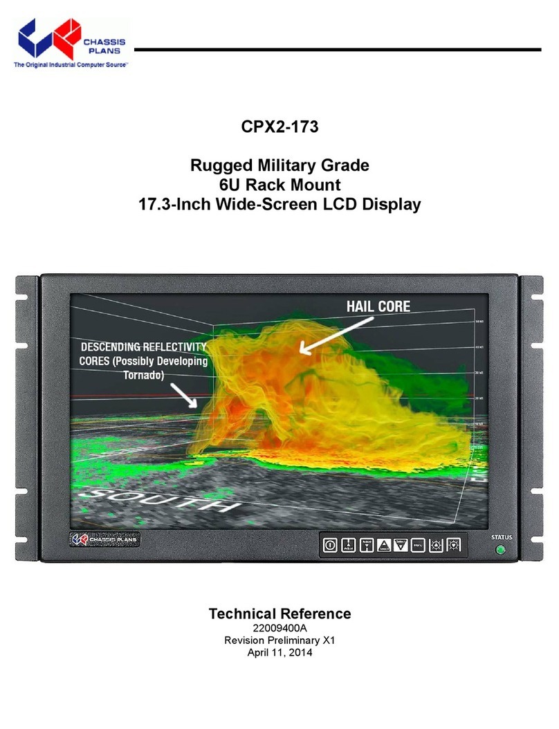
Chassis Plans CPX1-241 Use and care manual

CPX1-241
Rugged Military Grade
Rack Mount 24-Inch LCD Panel
with MultiTouch IR Touch Screen
Technical Reference
Revision A
6/12/2013

This Page Intentionally Blank

Warranty The product is warranted against material and manufacturing defects for two years from
date of delivery. Buyer agrees that if this product proves defective Chassis Plans’ is
only obligated to repair, replace or refund the purchase price of this product at Chassis
Plans’ discretion. The warranty is void if the product has been subjected to alteration,
neglect, misuse or abuse; if any repairs have been attempted by anyone other than
Chassis Plans; or if failure is caused by accident, acts of God, or her causes beyond the
control of Chassis Plans. Chassis Plans reserves the right to make changes or
improvements in any product without incurring any obligation to similarly alter products
previously purchased.
In no event shall Chassis Plans be liable for any defect in hardware or software or loss
or inadequacy of data of any kind, or for any direct, indirect, incidental or consequential
damages arising out of or in connection with the performance or use of the product or
information provided. Chassis Plans’ liability shall in no event exceed the purchase
price of the product purchased hereunder. The foregoing limitation of liability shall be
equally applicable to any service provided by Chassis Plans.
Return Policy Products returned for repair must be accompanied by a Return Material Authorization
(RMA) number, obtained from Chassis Plans prior to return. Freight on all returned
items must be prepaid by the customer, and the customer is responsible for any loss or
damage caused by common carrier in transit. Items will be returned from Chassis Plans
via Ground, unless prior arrangements are made by the customer for an alternative
shipping method
To obtain an RMA number, call us at 858-571-4330. We will need the following
information:
Return company address and contact
Model name and model # from the label on the back of the display
Serial number from the label on the back of the display
Description of the failure
An RMA number will be issued. Mark the RMA number clearly on the outside of each
box, include a failure report for each board and return the product(s) to our San Diego,
CA facility:
Chassis Plans
10123 Carroll Canyon Rd.
San Diego, CA 92131
Attn: Repair Department

Trademarks “The Original Industrial Computer Source”, “Systems Engineered to Perform” and
Chassis Plans are registered trademarks of Chassis Plans, LLC.
IBM, PC/AT, VGA, EGA, OS/2 and PS/2 are trademarks or registered trademarks of
International Business Machines Corp.
Intel is a registered trademark of Intel Corporation.
MS-DOS and Microsoft are registered trademarks of Microsoft Corp.
All other brand and product names may be trademarks or registered trademarks of their
respective companies.
Liability
Disclaimer This manual is as complete and factual as possible at the time of printing; however, the
information in this manual may have been updated since that time. Chassis Plans
reserves the right to change the functions, features or specifications of their products at
any time, without notice.
Copyright © 2013 by Chassis Plans. All rights reserved.
E-mail: Support@chassisplans.com
Web: www.chassisplans.com
Chassis Plans
10123 Carroll Canyon Road • San Diego, CA 92131

Table of Contents
Chapter1‐Introduction_______________________________________________________________1
Description_____________________________________________________________________________1
GenesisBasedLCDController_______________________________________________________________2
Table1–SupportedVideoResolutions____________________________________________________________3
RackMounting__________________________________________________________________________3
Photos_________________________________________________________________________________4
Photo1‐FrontView___________________________________________________________________________4
Photo2‐RearView___________________________________________________________________________4
Photo3‐BottomView__________________________________________________________________________4
Photo4‐BottomRearView_____________________________________________________________________4
Photo5‐RearViewExploded____________________________________________________________________4
Photo6‐I/OConnections_______________________________________________________________________5
Specifications____________________________________________________________________________6
ENCLOSURE____________________________________________________________________________________6
MOUNT‐ON‐RACKADAPTERBRACKETS______________________________________________________________6
24”DISPLAY____________________________________________________________________________________6
DISPLAYENHANCEMENTOPTIONS__________________________________________________________________6
OPTIONALFEATURES/OPTIONS___________________________________________________________________6
INFRAREDTOUCHSCREENOPTION_________________________________________________________________6
AUDIOAMPLIFIER_______________________________________________________________________________6
SPEAKERS_____________________________________________________________________________________6
IRREMOTECONTROL____________________________________________________________________________6
POWERSUPPLYOPTIONS_________________________________________________________________________6
Table2–Specifications________________________________________________________________________6
LCDDVI/HDMI/VGAInputFeatures:________________________________________________________________7
ControllerFeatureSummary______________________________________________________________________7
Table3–VideoControllerSpecifications___________________________________________________________7
HD‐SD/SDIOption________________________________________________________________________8
HD‐SD/SDISpecification:_________________________________________________________________________8
SupportedVideoModes__________________________________________________________________________8
Table4–HD‐SD/SDIInputOption________________________________________________________________8
Figure1–CPX1‐241CustomerDrawing___________________________________________________________9
Figure2–CPX1‐241MountingAdapterCustomerDrawing___________________________________________10
LCDEnhancements______________________________________________________________________11
Figure3–EMIShieldingEffectivenessofMicroMeshEMIFilter_______________________________________11
Figure4–ComparisonofReflectionswithandwithoutOpticalBonding________________________________11
Figure5–ComparisonwithandwithoutOpticalBonding____________________________________________12
DurableAnti‐ReflectionOleophobicCoating(DARO)___________________________________________12
KeyFeatures__________________________________________________________________________________12
Figure6–ComparisonwithandwithoutOpticalBonding____________________________________________13
Specifications___________________________________________________________________________13
Chapter2–InfraredTouchScreenOption________________________________________________14
Description____________________________________________________________________________14
Figure7–InfraredTouchScreenExample________________________________________________________14
Figure8–ExamplesofDualTouchGesturing______________________________________________________14

Chapter3–PowerSupplyOptions______________________________________________________15
ACInputPowerSupply___________________________________________________________________15
Table5‐ACInputSupplySpecifications__________________________________________________________15
Photo6‐ACPowerSupply(150W)______________________________________________________________15
MIL‐STD‐704/1275DCInputConverter______________________________________________________16
OperatingSpecifications_________________________________________________________________________16
Connectors___________________________________________________________________________________16
EnvironmentalSpecifications_____________________________________________________________________16
Table6‐MIL‐STD‐704/1275APowerSupplySpecifications___________________________________________16
Chapter4–OrderingInformation______________________________________________________17
Chapter5‐PackageContents__________________________________________________________19
Table7‐PackageContents____________________________________________________________________19
Chapter6‐Installation_______________________________________________________________21
RackInstallation________________________________________________________________________21
Figure9‐RackMountingHoleSpacing___________________________________________________________21
InstallingtheCPX1‐241___________________________________________________________________21
Figure10–InstallingtheMountingAdapterBracket________________________________________________22
ConnectingtheDisplay___________________________________________________________________23
ControllerRearPanelConnections_________________________________________________________23
DVI/HDMI/VGAInputFeatures:___________________________________________________________________23
Photo7–CPX1‐241BottomViewandI/O_________________________________________________________24
Table8‐RearPanelConnections_______________________________________________________________24
Chapter7–LCDOperation____________________________________________________________25
LCDFrontPanelControls_________________________________________________________________25
Table9‐FrontPanelControls__________________________________________________________________25
LCDControllerOSDMenus________________________________________________________________26
Table10‐LCDControllerOSDMenus____________________________________________________________30
AppendixA–DisplaySerialControlProgramming_________________________________________31
RS‐232SerialControl_____________________________________________________________________31
EthernetControl________________________________________________________________________31
LCDControllerSerial/EthernetControlFunctions_____________________________________________31
TableA‐1‐CommandstoImplementSwitchMountControlButtons___________________________________31
TableA‐2‐ParameterSetting‐Immediate,Relative,ResetandQuery_________________________________41
TableA‐3‐OtherControl_____________________________________________________________________43
TextViaRS232Command________________________________________________________________________44
TableA‐4–TextViaRS232Command____________________________________________________________45
DisplayMarkCommand_________________________________________________________________________46
TableA‐5–DisplayMarkCommand_____________________________________________________________47
TableA‐6‐HextoASCIIConversionTable________________________________________________________48
AppendixB–AutoColorGain__________________________________________________________49
ImageB‐1–AutoColorGainExample____________________________________________________________49
AppendixC–RemoteControl__________________________________________________________51
ImageC‐1–RemoteControl___________________________________________________________________51
TableC‐1–RemoteControlFunctions___________________________________________________________52

AppendixD–FunctionalDescriptionforDe‐InterlacingModes_______________________________53
AppendixE–PIPMixTable____________________________________________________________55
TableE‐1–PIPMixTable______________________________________________________________________55
AppendixF–EthernetNetworkConnection______________________________________________57
ConnectinganetworkporttoCPX1‐241_____________________________________________________57
GettheIPaddressusingDHCP_____________________________________________________________58
WebConsole___________________________________________________________________________58
IPLocator______________________________________________________________________________58
ImageF‐1–IPLocatorScreenShow_____________________________________________________________58
Networkconfiguration___________________________________________________________________58
ImageF‐2–NetworkDropDown_______________________________________________________________58
ImageF‐3–NetworkConfigureSettings__________________________________________________________59
ConnecttoasingleCPX1‐241______________________________________________________________59
TableF‐1–RemoteControl____________________________________________________________________59
ImageF‐4–IPAddressLocator_________________________________________________________________60
ImageF‐5–IPAddressSettingandEnable________________________________________________________60
ConnecttomultipleCPX1‐241s____________________________________________________________60
TableF‐2–RemoteControl____________________________________________________________________60
ImageF‐6–DHCPTableScreenshot_____________________________________________________________61
ImageF‐7–NATFowardingScreenshot__________________________________________________________61
AppendixG–DVI‐DversusDVI‐IConnectors______________________________________________63
Overview______________________________________________________________________________63
Connectors_____________________________________________________________________________63

This Page Intentionally Blank

Chassis Plans CPX1-241 Technical Reference Chapter 1 - Introduction
Page 1
Chapter 1 - Introduction
Description
The CPX1-241 is a rugged military grade and industrial grade high performance 9U mount-on-rack LCD panel
display offering 24-inch TFT LCD display with LED backlight. The display includes a bonded anti-reflective glass
cover with an optional bonded mesh EMI filter and an Infrared dual-touch touch screen.
The CPX1-241 family is designed to meet Mil-S-901D and MIL-STD-810G and includes solid and lightweight
5052-H32 aluminum construction and locking stainless hardware throughout. As a 24-inch display is wider than
19-inches, the display mounts in front of the rack and mounting brackets can be specified for racks with different
front-to-rack-rail spacing.
The 24-inch display offers 1920 x 1200 native resolution, LED backlighting, 300nit brightness, 1000:1 native
contrast (before installing the AR filter), and 89 degree viewing angle. The Pixel Pitch for the 24-inch display is
.270 x .270mm. The display offers 16.7 million colors (True Color).
The display is equipped standard with a bonded glass overlay with a DARO oleophobic anti-reflective (AR)
coating. This AR coating minimizes finger prints and repels dirt, moisture, and other contaminates to improve
image clarity. The coating is highly resistant to abrasion and is easily cleaned.
An optional embedded mesh EMI filter in front of the display is available for compliance with military EMI
standards. The glass is optically bonded to the front of the display with optically clear index matched adhesive
for superior viewing and ruggedness. A 6mm copper bus bar around the entire glass stack-up provides effective
EMI grounding. The contrast is significantly enhanced with this Anti Reflective glass stack-up in high bright
environments.
An optional infrared dual-touch touch screen is available. Infrared touch screen technology offers a multitude of
advantages over traditional capacitive or resistive touch screens. The IR touch screen can be used with bare
fingers, gloves or any other pointer. Multi-touch control is supported for gesture recognition, etc. Touch
activations is unlimited and there is no concern with damage to the touch surface. One compelling advantage to
IR Touch is the ability to install the anti-reflective coated glass bonded to the display for high-bright
environments. Another prime benefit of IR Touch is that this is a passive technology with no emitted EMI.
The CPX1-241 provides a high quality advanced scaling controller with a Genesis chipset. The rugged LCD
controller offers inputs for virtually any video signal including aRGB, DVI-D, HDMI, and optional video
(NTSC/PAL/SECAM, Composite, S-video, SD (YCbCr) and HD (YPbPr) component). An optional HD-SDI
adapter is available for professional and broadcast video applications. This is a specifically ruggedized
controller offering as standard conformal coating with high shock/vibration and temperature extreme tolerances.
The LCD supports full screen image expansion, on-screen PIP (Picture in Picture), Picture by Picture, and image
marker. Rounding out the display features is an optional infrared control and serial or Ethernet command port
including on-screen text overlay generation.
Included standard is a built-in 2 watt stereo amplifier and two speakers. The speakers are located at the bottom
of the front bezel of the display.
The CPX1-241 is primarily designed for rugged Military applications but can be used in Industrial, Commercial,
or Broadcast applications where reliability, quality and long program life availability preclude the use of cheaply
made imported units.
As with all Chassis Plans products, a wide variety of custom options can be configured per customer or
application specific requirements. Contact your Sales Engineer to discuss your particular requirements.

Chassis Plans CPX1-241 Technical Reference Chapter 1 - Introduction
Page 2
Genesis Based LCD Controller
The LCD Controller is a key component in any display system. This is a long life revision controlled military
grade component. The controller board selected is based on the Genesis FLI30436 LCD Controller. It
provides:
Faroudja® signal processing including TrueLife™ Video Enhancer
Next generation 10-bit Faroudja DCDi Cinema® format conversion
Dual 10 bit video decoders for up to 1.06 billion colors
VBI support for Teletext, Closed Captioning V-Chip and other services
Worldwide video standard support
Picture-in-Picture (PIP) and Picture-byPicture (PBP)
Analog Video Capture up to 162 MHz (up to WUXGA 1920 x 1200 @ 60 Hz) support
Digital Video Capture up to 165 MHz
1-bit Advanced Color Management (ACM-3D) and Adaptive Contrast Control (ACC)
Optional 3G HD-SDI adaptor for professional and broadcast video applications
Text overlay via Serial Port or Ethernet
Full command of all OSD functions through Serial Comm port, Ethernet or IR remote control
This ruggedized military grade controller is rated for operating at -40 to +80 deg C, uses low mass tantalum
capacitors for maximum vibration and shock tolerance and is conformal coated for extreme ruggedness. MTBF
for the controllers is in excess of 100K hours.
The controller will provide input up/down scaling of virtually any input signal to scale the image to the 1920x1200
native LCD panel resolution. It provides for PC, Apple and Sun input resolutions.
Supported Resolutions:
720 x 400 @ 70 Hz Digital Separate Sync 720 x 400 @ 70 Hz Sync on Green
640 x 480 @ 60 Hz Digital Separate Sync 640 x 480 @ 60 Hz Sync on Green
640 x 480 @ 60Hz Composite Sync
640 x 480 @ 72 Hz Digital Separate Sync 640 x 480 @ 72 Hz Sync on Green
640 x 480 @ 72Hz Composite Sync
640 x 480 @ 75 Hz Digital Separate Sync 640 x 480 @ 75 Hz Sync on Green
640 x 480 @ 75Hz Composite Sync
800 x 600 @ 56 Hz Digital Separate Sync 800 x 600 @ 56 Hz Sync on Green
800 x 600 @ 56 Hz Composite Sync
800 x 600 @ 60 Hz Digital Separate Sync 800 x 600 @ 60 Hz Sync on Green
800 x 600 @ 60 Hz Composite Sync
800 x 600 @ 72 Hz Digital Separate Sync 800 x 600 @ 72 Hz Sync on Green
800 x 600 @ 72 Hz Composite Sync
800 x 600 @ 75 Hz Digital Separate Sync 800 x 600 @ 75 Hz Sync on Green
800 x 600 @ 75 Hz Composite Sync
1024 x 768 @ 60 Hz Digital Separate Sync 1024 x 768 @ 60 Hz Sync on Green
1024 x 768 @ 60 Hz Composite Sync
1024 x 768 @ 70 Hz Digital Separate Sync 1024 x 768 @ 70 Hz Sync on Green
1024 x 768 @ 70 Hz Composite Sync
1024 x 768 @ 75 Hz Digital Separate Sync 1024 x 768 @ 75 Hz Sync on Green
1024 x 768 @ 75 Hz Composite Sync

Chassis Plans CPX1-241 Technical Reference Chapter 1 - Introduction
Page 3
Supported Resolutions (continued)
1280 x 1024 @ 60 Hz Digital Separate Sync 1280 x 1024 @ 60 Hz Sync on Green
1280 x 1024 @ 60 Hz Composite Sync
1280 x 1024 @ 75 Hz Digital Separate Sync 1280 x 1024 @ 75 Hz Sync on Green
1280 x 1024 @ 75 Hz Composite Sync
1600 x 1200 @ 60 Hz Digital Separate Sync 1600 x 1200 @ 60 Hz Sync on Green
1600 x 1200 @ 60 Hz Composite Sync
1920 x 1080 @ 60 Hz Digital Separate Sync 1920 x 1080 @ 60 Hz Sync on Green
1920 x 1080 @ 60 Hz Composite Sync
1920 x 1200 @ 60 Hz Digital Separate Sync 1920 x 1200 @ 60 Hz Sync on Green
1920 x 1200 @ 60 Hz Composite Sync
720 x 480i NTSC
720 x 480i NTSC 4.43
720 x 576i PAL
720 x 576i PAL M
720 x 576i SECAM
Other video formats can be supported by customized firmware. Contact your Sales Engineer for details.
Table 1 – Supported Video Resolutions
Rack Mounting
The CPX1-241 is mounted in front of the rack using included brackets. The width of the 24-inch display is wider
than the opening in a 19-inch rack. A selection of mounting adapters is available for different rack
configurations. Some racks are flush mounted while others have the mounting rails inset from the front of the
rack. Contact your Sales Engineer for details. See Photo 5 below.

Chassis Plans CPX1-241 Technical Reference Chapter 1 - Introduction
Page 4
Photos
Photo 1- Front View
Photo 2- Rear View
Photo 3-Bottom View
Photo 4- Bottom Rear View
Photo 5- Rear View Exploded

Chassis Plans CPX1-241 Technical Reference Chapter 1 - Introduction
Page 5
Photo 6- I/O Connections

Chassis Plans CPX1-241 Technical Reference Chapter 1 - Introduction
Page 6
Specifications
ENCLOSURE
9U (15.72”) x 3.19” deep (plus mounting bracket)
Front Panel 5052-H32 aluminum alloy
Body made of 5052-H32 aluminum alloy
All stainless steel hardware
All self locking pressed in fasteners where
appropriate
Powder coat black, medium texture, for ruggedness
Other colors optionally available
Designed to Mil-Spec Standards to Satisfy Military,
Industrial and Commercial Requirements
Compact Enclosure for Limited Depth Installation
Weight: 35lbs
MOUNT-ON-RACK ADAPTER BRACKETS
Adapts display to mount to front of 19-inch rack
Brackets for flush mounting, 1-inche and 2-inch
offset.
24” DISPLAY
24" TFT LCD 1920x1200, LED Backlight
Surface Treatment : Oleophobic Anti-Reflective
(AR) coated glass bonded with optically clear
index matched adhesive
Display Colors: 16.7 Million
Response Time: 12mS Typical
Viewing Angle: 89 deg
Contrast Ratio: 1000:1 typical native
Brightness: 300cd/m2 typical
Pixel Pitch: 0.270mm x 0.270mm
Pixel Arrangement: R.G.B Stripe
Power Management: EPA Energy Star, VESA
DPMS
Operating Temperature: 0 to + 50 Deg C
Storage Temperature: -20 to +60 Deg C
DISPLAY ENHANCEMENT OPTIONS
EMI Shield (fine wire mesh embedded in AR glass
adhesive)
OPTIONAL FEATURES / OPTIONS
Customer Specified Paint Color
Customer Logo
Custom sheet metal and mechanical features
INFRARED TOUCH SCREEN OPTION
Resolution: 4096 x 4096 touch points
Input: gloved hand, finger, or any other pointer
Touch activation force: none
Touch times: unlimited
Minimum touch object: 8mm
Sealability: IP65 from the front
Can be used in conjunction with AR Glass and/or
EMI Filter over LCD
Supports dual-touch gesture recognition (Windows 7
or 8)
Single Touch Drivers for:
Windows
Mac OS
Win CE
Linux
Android
AUDIO AMPLIFIER
Input Impedance: 6.8ohm
Output Power: 2.0W into 4Ω
Distortion: <2%
Gain: 0 to 21dB
SPEAKERS
22 x 33mm Cone
Input Power: 2W
Cone treated for water resistance
IR REMOTE CONTROL
Front panel sensor
Controls OSD and Video Source
POWER SUPPLY OPTIONS
DC 12 Volt Input
12V DC @ 8 A
AC Input
90 to 260VAC, auto selecting
47-63 HZ
MIL-STD-704/1275A DC/DC Converter
True compliance for military 28VDC nominal
vehicle inputs
18 to 36VDC input
See the appropriate power supply section for complete
power supply specifications.
Table 2 – Specifications

Chassis Plans CPX1-241 Technical Reference Chapter 1 - Introduction
Page 7
LCD DVI/HDMI/VGA Input Features:
Harsh Environment LCD Controller
Inputs:
Analog RGB: 75Hz at SXGA, WXGA, XGA,
SVGA, VGA
With auto detect of Digital
Separate Sync, Sync-On-Green &
Composite Sync. Auto detects
VGA ~WUXGA interlaced &
noninterlaced.
DVI-D/HDMI: 60Hz at WUXGA
75Hz at SXGA, WXGA, XGA,
SVGA, VGA
Optional Video: NTSC /PAL / SECAM (Interlaced)
Composite Video, S-Video
SD Component (YCbCr) (Optional)
HD Component (YPbPr) (Optional)
Dual Channel HD-SDI (Optional)
Image Scaling: Up / down scaling to fit input to
panel resolution.
Image Control: Brightness, Contrast, Saturation,
Hue, Frequency, Phase, Color
temperature, Image position, Hue,
Gamma.
Other Features: System information, OSD position,
Scaling to fill screen and fill to
aspect ratio, OSD timeout, Factory
reset, OSD menu transparency,
Picture In Picture – Variable
position with 18 sizes selection
and Picture By Picture,
Programmable hot keys
Controller Feature Summary
Brightness – LCD
Brightness – Backlight
Contrast
Saturation & Hue
Sharpness
Blue only, Red only, Green only
Monochrome Mode
Auto Color Gain
Gamma Curve Control
Color Temperature
Picture-in-Picture
Auto Source Seek
Auto Picture Setup
Wide Screen Mode Detection
Manual Clock / Phase / Position
De-Interlacing Mode
Auto Power
Up- and Down-Scaling
Image Orientation / Flip
Freeze Frame
Zoom / Pan
OSD Position / Transparency
Audio Volume
Programmable Default Settings
OEM Protected Setup Areas
Power Up Configuration
BIOS Upgrade Via RS-232
White Balance
Real Time Clock
RS-232 Text Overlay
Table 3 –Video Controller Specifications

Chassis Plans CPX1-241 Technical Reference Chapter 1 - Introduction
Page 8
HD-SD/SDI Option
The CPX1-241 can be optionally configured with a broadcast quality HD-SD/SDI input. Fully compliant with the
SMPTE 259M-C, SMPTE 292M, SMPTE 424 and 425M standard. The option provides a re-clocked loop through
output for “daisy chaining” multiple monitors or other equipment to the same HD-SDI source.
HD-SD/SDI Specification:
Interface SMPTE 292M, 259M-C, 424M,
Standards 425M (Level A)
Input Channels: One (1)
Loop Through: Yes
Other Features:
Supports 1.5Gbits & 3Gbits bit rate input
signal support.
Single channels input port supported
HD--‐SDI re--‐clock loop through output
AFD support
Stereo embedded audio support
Supported Video Modes
576i50(PAL)
480i60(NTSC)
720p60(4:2:2)
720p59.94(4:2:2)
720p50(4:2:2)
720p30(4:2:2)
720p29.97(4:2:2)
720p25(4:2:2)
1035i60(4:2:2)
1035i59.94(4:2:2)
1080p30(4:2:2)
1080p29.97(4:2:2)
1080p25(4:2:2)
1080p24(4:2:2)
1080p23.98(4:2:2)
1080psf30(4:2:2)
1080psf25(4:2:2)
1080psf24(4:2:2)
1080psf23.98(4:2:2)
1080i60(4:2:2)
1080i59.94(4:2:2)
1080i50(4:2:2)
1080p60(4:2:2)
1080p50(4:2:2)
Table 4 –HD-SD/SDI Input Option

Chassis Plans CPX1-241 Technical Reference Chapter 1 - Introduction
Page 9
Figure 1 – CPX1-241 Customer Drawing

Chassis Plans CPX1-241 Technical Reference Chapter 1 - Introduction
Page 10
Figure 2 – CPX1-241 Mounting Adapter Customer Drawing

Chassis Plans CPX1-241 Technical Reference Chapter 1 - Introduction
Page 11
LCD Enhancements
In the CPX family of rugged military grade LCD displays, Chassis Plans starts with Grade A Industrial Quality
LCD panels selected for optical performance, high reliability and long product life cycle. Standard, in order to not
only ruggedize the LCD, but to also enhance the mechanical, optical and EMI properties of the finished unit
Chassis Plans optically bonds a layer of glass to the front of the LCD panel which is coated with an oleophobic
Anti-Reflective (AR) coating. The adhesive is optically clear and refractive index matched to eliminate interface
reflections.
An additional option provides for a fine stainless steel mesh to be embedded in the adhesive for the AR glass to
provide superior EMI shielding. See Figure 2 for attenuation values. The Micro Mesh provides >50dB of
shielding (30 MHz – 1 GHz) with 90% visible light transmission and zero Moiré fringing.
Figure 3 – EMI Shielding Effectiveness of MicroMesh EMI Filter
Figure 4 – Comparison of Reflections with and without Optical Bonding
The resulting structure has greatly enhanced optical characteristics in high ambient light conditions. The optical
adhesive used is a silicone RTV and offers other benefits mechanically to the LCD as well. The adhesive
remains pliable and therefore acts as a shock absorbing medium for the front of the LCD. Together with the
additional layer of glass provides a very rugged composite structure. Another benefit is that should breakage
actually occur the shards of glass will be retained together to prevent injury to personnel. The adhesive also
prevents any condensation from building up in the air gap between the layers of glass which would cause
Reflected
Light
Total
22.5%
4.5%
4.5%
4.5%
4.5%
4.5%
Without Optical Bonding
Or AR Coating
Reflected
Light
Total
0.7%
0.3%
With Optical Bonding
And AR Coating
0.1%
0.1%
0.1%
0.1%

Chassis Plans CPX1-241 Technical Reference Chapter 1 - Introduction
Page 12
fogging of the display. Finally, the added mass bonded to the front of the LCD display adds a thermal
conduction path to help dissipate the heat generated in the backlights themselves.
By eliminating the majority of reflected light, the apparent contrast improves making the display more legible in
high bright situations.
Photo Courtesy of
GDS Clearview
Figure 5– Comparison with and without Optical Bonding
Durable Anti-Reflection Oleophobic Coating (DARO)
Key Features
Repels fingerprints
Easy to clean with a soft cloth
More than 450,000-rub resistant
Chemically-inert coating resists stains
Smooth surface minimizes abrasion and friction
Water contact angle >110°
Withstands more than 90 days of salt-fog exposure
Less than 0.4 percent photopic brightness
Soft blue hue in reflection
8H pencil hardness
Most touch screen use smooth glass without an anti-reflection (AR) coating because it offers the most durable
and easy-to-clean option. However, fingerprints are difficult to remove, and many indoor and outdoor lighting
conditions generate glare off a smooth glass surface.
Offering an AR coating on the CPX1-241 display greatly improves the user experience. The oleophobic coating
stands up to hundreds of thousands of finger touches and rubs.
DARO coating is a breakthrough for touch applications. The coating nanostructure forms multiple, covalent
bonds to provide outstanding durability.
Table of contents
Other Chassis Plans Monitor manuals
