Chassis Plans CPX2-173 Use and care manual

CPX2-173
Rugged Military Grade
6U Rack Mount
17.3-Inch Wide-Screen LCD Display
Technical Reference
22009400A
Revision Preliminary X1
April 11, 2014

Warranty The product is warranted against material and manufacturing defects for two years from
date of delivery. Buyer agrees that if this product proves defective Chassis Plans’ is only
obligated to repair, replace or refund the purchase price of this product at Chassis Plans’
discretion. The warranty is void if the product has been subjected to alteration, neglect,
misuse or abuse; if any repairs have been attempted by anyone other than Chassis Plans;
or if failure is caused by accident, acts of God, or her causes beyond the control of Chassis
Plans. Chassis Plans reserves the right to make changes or improvements in any product
without incurring any obligation to similarly alter products previously purchased.
In no event shall Chassis Plans be liable for any defect in hardware or software or loss or
inadequacy of data of any kind, or for any direct, indirect, incidental or consequential
damages arising out of or in connection with the performance or use of the product or
information provided. Chassis Plans’ liability shall in no event exceed the purchase price
of the product purchased hereunder. The foregoing limitation of liability shall be equally
applicable to any service provided by Chassis Plans.
Return Policy Products returned for repair must be accompanied by a Return Material Authorization
(RMA) number, obtained from Chassis Plans prior to return. Freight on all returned items
must be prepaid by the customer, and the customer is responsible for any loss or damage
caused by common carrier in transit. Items will be returned from Chassis Plans via
Ground, unless prior arrangements are made by the customer for an alternative shipping
method
To obtain an RMA number, call us at 858-571-4330. We will need the following
information:
Return company address and contact
Model name and model # from the label on the back of the display
Serial number from the label on the back of the display
Description of the failure
An RMA number will be issued. Mark the RMA number clearly on the outside of each box,
include a failure report for each board and return the product(s) to our San Diego, CA
facility:
Chassis Plans.
10123 Carroll Canyon Road
San Diego, CA 92131
Attn: Repair Department

Trademarks “The Original Industrial Computer Source”, “Systems Engineered to Perform” and Chassis
Plans are registered trademarks of Chassis Plans, LLC.
IBM, PC/AT, VGA, EGA, OS/2 and PS/2 are trademarks or registered trademarks of
International Business Machines Corp.
Intel is a registered trademark of Intel Corporation.
MS-DOS and Microsoft are registered trademarks of Microsoft Corp.
All other brand and product names may be trademarks or registered trademarks of their
respective companies.
Liability
Disclaimer This manual is as complete and factual as possible at the time of printing; however, the
information in this manual may have been updated since that time. Chassis Plans
reserves the right to change the functions, features or specifications of their products at
any time, without notice.
Copyright © 2014 by Chassis Plans. All rights reserved.
E-mail: Support@chassisplans.com
Web: www.chassis-plans.com
Chassis Plans
10123 Carroll Canyon Road • San Diego, CA 92131

This Page Intentionally Blank

Chassis Plans CPX2-173 Technical Reference Index
Table of Contents
Chapter1‐Introduction_______________________________________________________________1
Description_______________________________________________________________________________1
Table1–DisplaySpecifications____________________________________________________________________1
LCDEnhancements_________________________________________________________________________2
Figure1–EMIShieldingEffectivenessofITOCoating__________________________________________________2
Figure2–OpticalStackonLCD____________________________________________________________________2
Figure3–ComparisonofReflectionswithandwithoutOpticalBonding___________________________________3
Figure4–ComparisonwithandwithoutOpticalBonding_______________________________________________3
GenesisBasedLCDControllers________________________________________________________________4
Figure5–ControllerSpecifications_________________________________________________________________4
Photos___________________________________________________________________________________5
Specifications______________________________________________________________________________6
Enclosure________________________________________________________________________________________6
Display__________________________________________________________________________________________6
DisplayEnhancementOptions_______________________________________________________________________6
PowerSupplyOptions______________________________________________________________________________6
Environmental____________________________________________________________________________________6
Table2–Specifications__________________________________________________________________________6
Figure6‐CCXOutlineDrawing____________________________________________________________________7
Chapter2–PowerSupplyOptions_______________________________________________________9
ACInputPowerSupply______________________________________________________________________9
Table3‐ACInputSupplySpecifications_____________________________________________________________9
Photo1‐ACPowerSupply_______________________________________________________________________9
12VDCInputTransientFilter________________________________________________________________10
Connectors_____________________________________________________________________________________10
Photo2‐12VDCInputFrontEndFilter_____________________________________________________________10
MIL‐STD‐704/127528VDCDCInput___________________________________________________________11
OperatingSpecifications___________________________________________________________________________11
Connectors_____________________________________________________________________________________11
EnvironmentalSpecifications_______________________________________________________________________11
Table4‐MIL‐STD‐704PowerSupplySpecifications___________________________________________________11
+/‐48VDCPowerSupply____________________________________________________________________12
OperatingSpecifications___________________________________________________________________________12
Connectors_____________________________________________________________________________________12
ElectricalSpecifications____________________________________________________________________________12
Table5‐48VDCPowerSupplySpecifications________________________________________________________12
Photo3‐48VDCPowerSupply____________________________________________________________________12
Chapter3–OrderingInformation______________________________________________________13
PartNumberMatrix______________________________________________________________________________13
ExamplePartNumbers____________________________________________________________________________13
Chapter4‐Installation_______________________________________________________________15
PackageContents________________________________________________________________________________15
Table6‐PackageContents______________________________________________________________________15
RackInstallation__________________________________________________________________________16

Chassis Plans CPX2-173 Technical Reference Index
Figure7‐RackMountingHoleSpacing_____________________________________________________________16
ConnectingtheDisplay_____________________________________________________________________17
StandardControllerRearPanelConnections___________________________________________________17
Photo4–StandardControllerRearPanelI/O________________________________________________________17
Table7‐RearPanelConnections–StandardController_______________________________________________17
AdvancedControllerRearPanelConnections___________________________________________________18
Photo5‐AdvancedHD/SDIControllerRearPanelI/O_________________________________________________18
Table8‐RearPanelConnections–AdvancedHD/SDIController________________________________________18
Chapter5‐Operation________________________________________________________________19
LCDFrontPanelControls___________________________________________________________________19
Table9‐FrontPanelControls____________________________________________________________________19
StandardControllerOSDMenus_____________________________________________________________20
AdvancedHD/SDIControllerOSDMenus______________________________________________________25
AppendixA–DisplaySerialControlProgramming_______________________________________27
RS‐232Serialcontrol_______________________________________________________________________27
ControllerSerialControlFunctions___________________________________________________________27
Table10‐StandardControllerCommandstoImplementSwitchMountControlButtons_____________________27
Table11‐StandardControllerParameterSetting‐Immediate,Relative,ResetandQuery____________________28
Table12‐StandardControllerOtherControl________________________________________________________38
Table13‐HextoASCIIConversionTable___________________________________________________________40
AppendixB–AutoColorGain__________________________________________________________41
ImageB‐1–AutoColorGainExample______________________________________________________________41
AppendixC–DVI‐DversusDVI‐IConnectors______________________________________________42
Overview________________________________________________________________________________42
Connectors_______________________________________________________________________________42
AppendixD–EthernetNetworkConnection______________________________________________43
ConnectinganetworkporttoCPX2‐173_______________________________________________________43
GettheIPaddressusingDHCP_______________________________________________________________44
WebConsole_____________________________________________________________________________44
IPLocator________________________________________________________________________________44
ImageD‐1–IPLocatorScreenShow_______________________________________________________________44
Networkconfiguration_____________________________________________________________________44
ImageD‐2–NetworkDropDown_________________________________________________________________44
ImageD‐3–NetworkConfigureSettings___________________________________________________________45
ConnecttoasingleCPX2‐173________________________________________________________________45
TableD‐1–RemoteControl______________________________________________________________________45
ImageD‐4–IPAddressLocator___________________________________________________________________46
ImageD‐5–IPAddressSettingandEnable__________________________________________________________46
ConnecttomultipleCPX2‐173_______________________________________________________________46
TableD‐2–RemoteControl______________________________________________________________________46
ImageD‐6–DHCPTableScreenshot_______________________________________________________________47
ImageD‐7–NATFowardingScreenshot____________________________________________________________47
Chassis Plans CPX2-173 Technical Reference Chapter 1 - Introduction
Page 1
Chapter 1 - Introduction
Description
The CPX2-173 is a military-grade high-performance 6U rack mount or panel mount LCD display offering 1920 x
1080 wide-screen high-definition resolution. The CPX2-173 is designed to meet Mil-Std 901D and MIL-STD-
810G and includes a solid milled aluminum front panel, lightweight 5052-H32 aluminum construction and locking
stainless hardware throughout. The CPX2-173 is ideal for mounting in a transit case for adverse environments
that would destroy lesser displays.
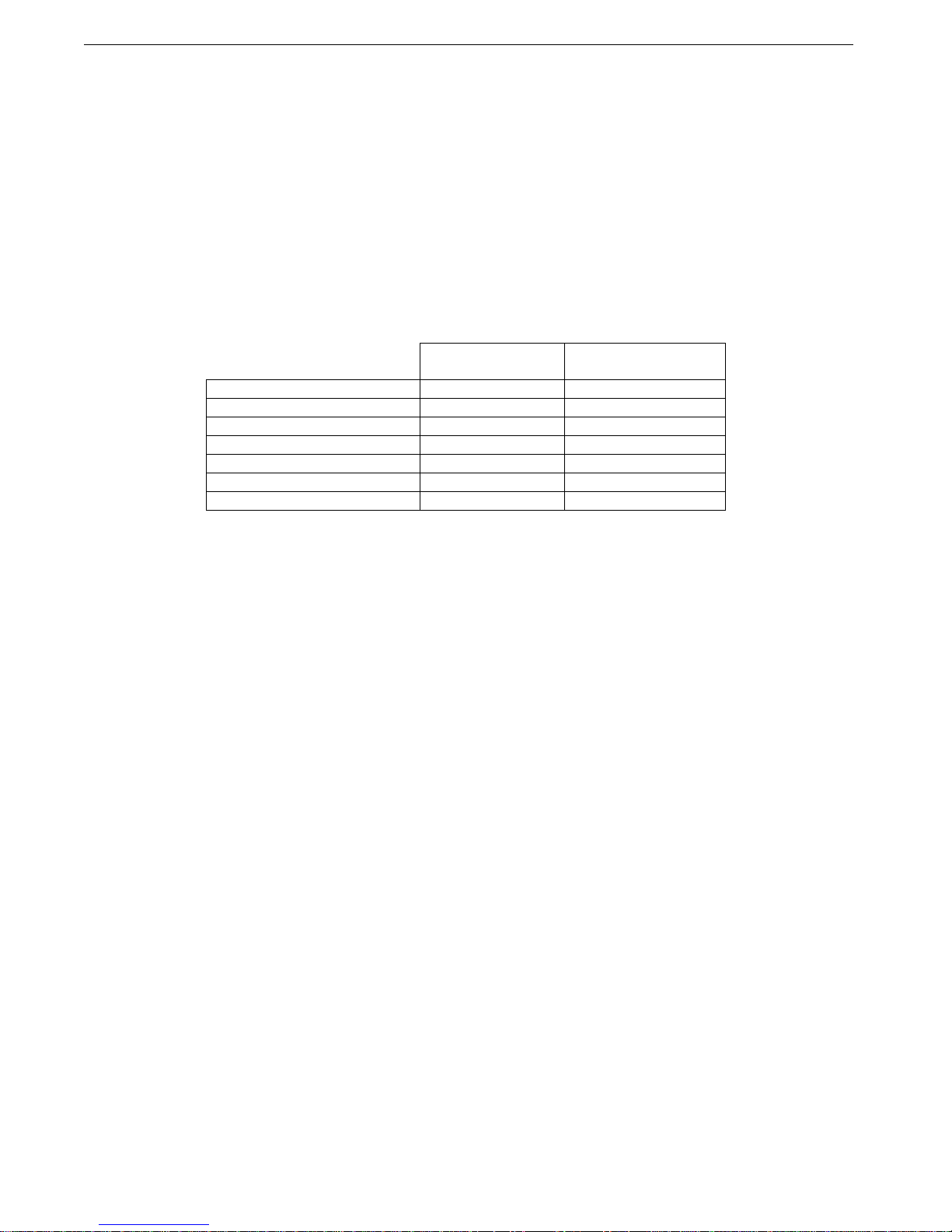
Two versions offer standard brightness or hi-bright for sunlight visibility.
CPX2-1731
Standard
CPX2-1732
Hi-Bright
Contrast Ratio 600:1 600:1
Viewing Angle (L/R/U/D) 80º 80º
Response Time 40ms 40ms
Brightness 400 cd/m
2
1000 cd/m
2
Backlight LED LED
Native Resolution 1920 x 1080 1920 x 1080
Aspect Ratio 16:9 16:9
Table 1 – Display Specifications
The displays are high-performance, long life TFT LCD’s offering a maximum native wide-screen resolution of
1920 x 1080. The displays offer optional optically bonded anti-reflective overlay glass. In addition, an optional
laminated 1.1mm soda lime glass with an ITO conductive EMI filter and an additional 1.1mm soda lime glass
overlay with anti-reflective (AR) coating. Both glass components are optically bonded to each other, and to the
front of the display, for superior viewing clarity and overall ruggedness. A 6mm copper bus bar surrounds the
entire glass stack-up and provides consistent grounding. A contrast ratio of approximately 1300:1 is delivered
with this ITO/Anti-Reflective glass stack-up. The front surface is an oleophobic anti-reflective coating resistant to
fingerprints.
The displays offer 16.7 million colors (True Color). The displays provide multiple signal input options including
aRGB, DVI-D, HDMI, Display Port, HD-SDI, NTSC, S-Video and Composite Video, depending on the controller.
The displays offer a choice of high quality advanced scaling controllers with a Genesis chipset. These are
specifically ruggedized controllers offering as standard conformal coating with high shock/vibration and
temperature extreme tolerances as well as long life product availability for assured delivery throughout multi-year
programs.
The Standard Controller offers DVI-D, VGA (aRGB), HDMI, NTSC, S-Video and CVS with an option for
Component (YCbCr) input. In addition, the Standard Controller supports Picture-In-Picture (PIP) and Picture-By-
Picture.
The Advanced HD-SDI Controller offers VGA (aRGB), HDMI, Display Port, HD-SDI and 3G HD-SDI.
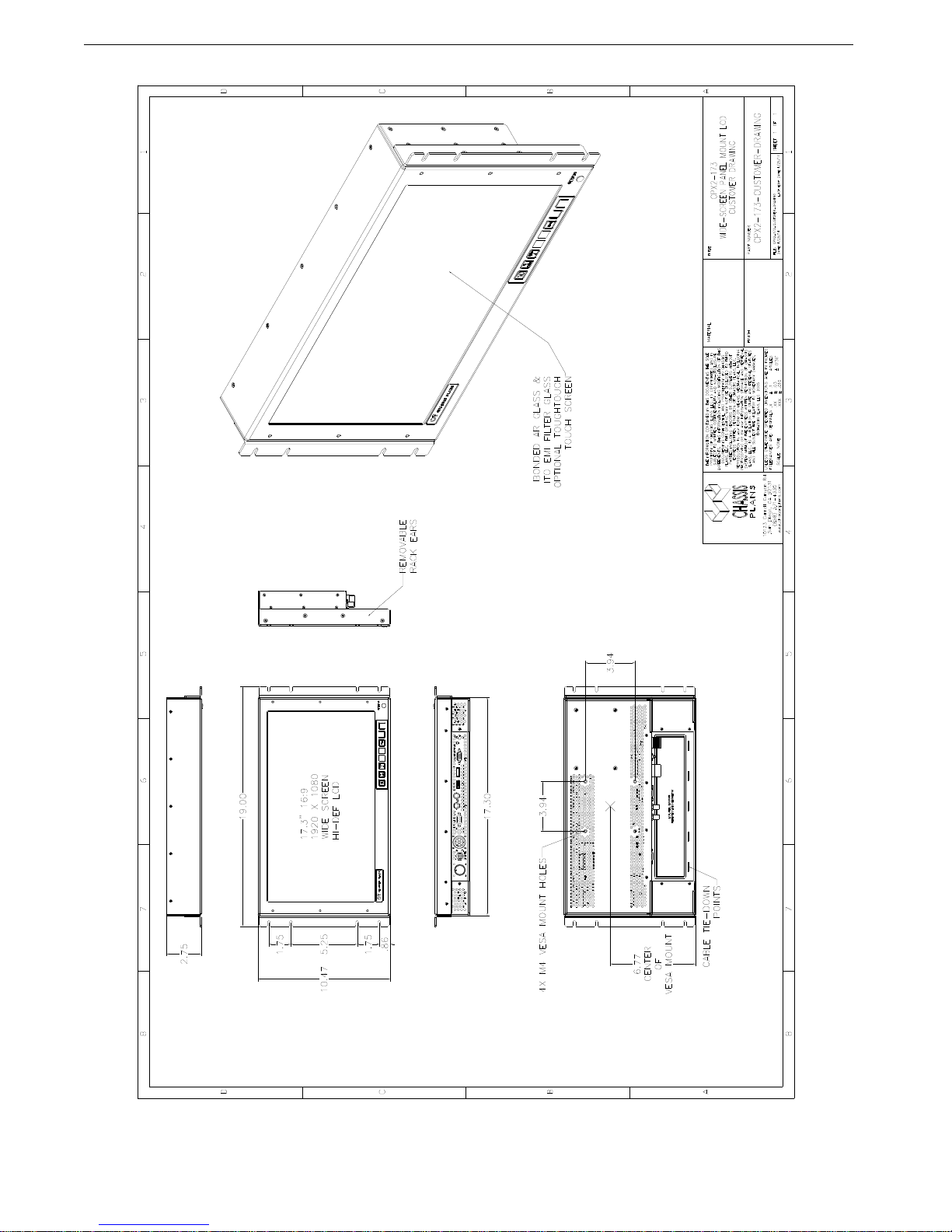
The display is only 6U (10.47-inches) high offering significant rack space savings. It can be rack mounted, panel
mounted, or mounted using a VESA adapter via the included VESA hole pattern on the rear of the unit. It is only
3.2-inches deep and power and signal cables exit down so as to not increase depth requirements.
As with all Chassis Plans products, a wide variety of custom options can be configured per customer or
application specific requirements. Contact your Sales Engineer to discuss your particular requirements.
Chassis Plans CPX2-173 Technical Reference Chapter 1 - Introduction
Page 2
LCD Enhancements
Chassis Plans starts with Grade A Industrial Quality LCD panels selected for optical performance, high reliability
and long product life cycle. In order to not only ruggedize the LCD, but to also enhance the mechanical, optical
and EMI properties of the finished unit, as an option, Chassis Plans optically bonds one 3mm anti-reflective or
two layers of coated 1.1 mm soda-lime float glass to the front of the LCD panel. The first layer is coated with an
Indium Tin Oxide (ITO) coating with a surface resistivity of <13.5 ohms/sq. See Figure 1 for attenuation values.
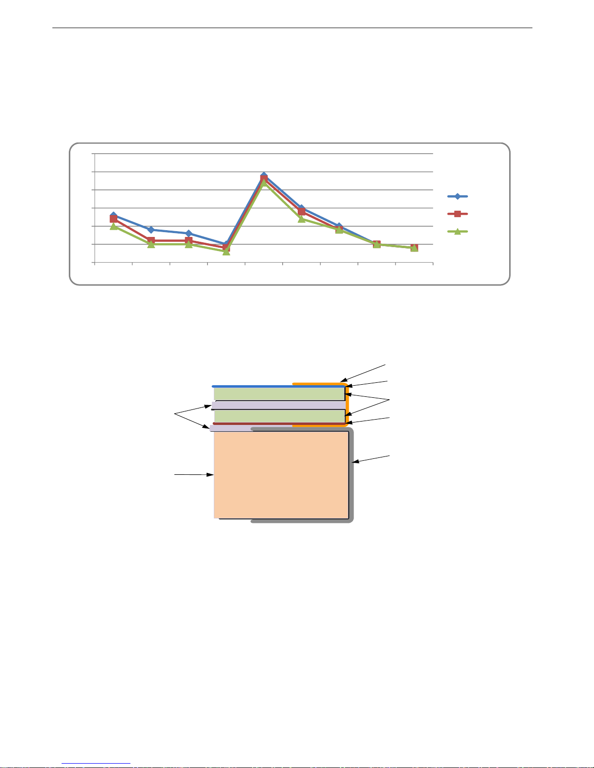
Figure 1 – EMI Shielding Effectiveness of ITO Coating
There is a Copper conductive buss bar that wraps around the edge of the glass to facilitate conduction from the
ITO coating to the front surface of the laminated structure to make a complete electrical shield around the face of
the LCD. See Figure 2 for details.
Figure 2 – Optical Stack on LCD
The second layer of glass is coated with an Oleophobic Anti-Reflective (AR) coating which matches the index of
refraction of air to eliminate surface reflections. These layers of coated glass are bonded together with an index
matching optical adhesive to eliminate internal reflections caused by the index of refraction mismatch between
the soda lime glass and air. This eliminates over 95% of unwanted glare from the screen. Please see Figure 3
below for more details.
20
25
30
35
40
45
50
30MHz 75MHz 100MHz 150MHz 200MHz 300MHz 500MHz 700MHz 1000MHz
15"LCD
17"LCD
19"LCD
AR Coating
ITO Coating
Soda Lime Float Glass
Copper Buss Bar
LCD Frame
O ptical Ind ex
Matching
Adhesive
LCD Panel
And
Backlight

Chassis Plans CPX2-173 Technical Reference Chapter 1 - Introduction
Page 3
Figure 3 – Comparison of Reflections with and without Optical Bonding
The resulting structure in conjunction with the CPX2-1732 Hi-Bright 1000nit panel has greatly enhanced optical
characteristics in high ambient light conditions. The optical adhesive used is a silicone RTV and offers other
benefits mechanically to the LCD as well. The adhesive remains pliable and therefore acts as a shock
absorbing medium for the front of the LCD. Together with the additional layers of glass provides a very rugged
composite structure. Another benefit is that should breakage actually occur the shards of glass will be retained
together to prevent injury to personnel. The adhesive also prevents any condensation from building up in the air
gap between the layers of glass which would cause fogging of the display. Finally, the added mass bonded to
the front of the LCD display adds a thermal conduction path to help dissipate the heat generated in the
backlights themselves.
By eliminating the majority of reflected light, the apparent contrast improves making the display more readable in
high bright situations. An alternative to improving the contrast is to increase the back light levels to overpower
the reflected light. The downside to this approach is the higher power requirements and higher heat generated
by the backlights.
Photo Courtesy of
GDS Clearview
Figure 4 – Comparison with and without Optical Bonding
Reflected
Light
Total
22.5%
4.5%
4.5%
4.5%
4.5%
4.5%
Without Optical Bonding
Or AR Coating
Reflected
Light
Total
0.7%
0.3%
With Optical Bonding
And AR Coating
0.1%
0.1%
0.1%
0.1%
Chassis Plans CPX2-173 Technical Reference Chapter 1 - Introduction
Page 4
Genesis Based LCD Controllers
The LCD Controller is a key component in any display
system and no expense has been spared in specifying the
Standard Controller and Advanced HD-SDI Controller
Genesis controllers. These are long life revision
controlled military grade components. The Genesis chip
set is the current gold standard for LCD controllers.
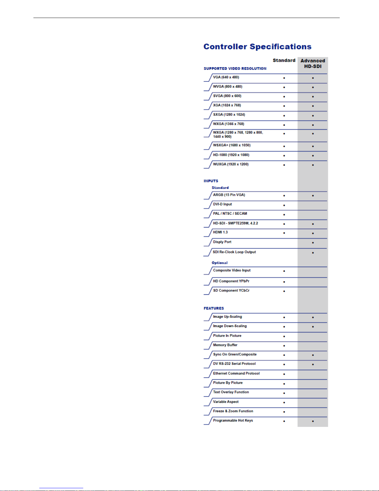
The controllers support 3x8-bit 16.7 million colors at up to
1920 x 1200. Refresh rates of 60Hz for WUXGA and
UXGA with higher refresh rates for lower resolutions
available. Computer input signals of VGA, SVGA, XGA,
SXGA, WXGA, UXGA and WUXGA are supported.
Video inputs of NTSC, PAL and SECAM are optionally
available. DVI inputs supports up to 1920 x 1080
WUXGA 60Hz signals.
These ruggedized military grade controllers are rated for
operating at -40 to +80 deg C, use low mass tantalum
capacitors for maximum vibration and shock tolerance
and are conformal coated for extreme ruggedness. The
coating is silicone resin conformal coating.(MOD) DEF-
STAN 59/47 Issue 4 &UL QMJU2 compliant
MTBF for the controllers is in excess of 150,000 to
200,000 hours.
Figure 5 – Controller Specifications

Chassis Plans CPX2-173 Technical Reference Chapter 1 - Introduction
Page 5
Photos
Connector details dependent on installed controller

Chassis Plans CPX2-173 Technical Reference Chapter 1 - Introduction
Page 6
Specifications
Enclosure
6U (10.47”) x 3.2” deep
Front Panel milled 5052 aluminum alloy
Body made of 5052-H32 aluminum alloy
All stainless steel hardware
All self-locking pressed in fasteners where
appropriate
Powder coat black, medium texture, for ruggedness
Other colors optionally available
Designed to Mil-Spec Standards to Satisfy Military,
Industrial and Commercial Requirements
Compact Enclosure for Limited Depth Installation
Weight: 9.7lbs (depending on model & features)
Display
17.3" Wide-Screen TFT LCD 1920 x 1080
Display Colors: 16.7 Million
Response Time: 40ms Typical
Viewing Angle: 80 deg
Contrast Ratio: 600:1 typical native
Brightness: 400cd/m2 standard (CPX2-1731),
1000cd/m2 enhanced daylight visibility (CPX2-
1732)
Pixel Pitch: 0.1989mm x 0.1989mm
Pixel Arrangement: R.G.B Stripe
Display Enhancement Options
3mm smudge-resistant anti-reflective coated soda
lime float glass,bonded to the LCD panel with
optical index matched adhesive
Laminate of 1.1mm smudge-resistant anti-reflective
coated soda lime float glass panel and a 1.1 mm
ITO coated glass panel(<12.5Ω/sq) grounded via
a copper buss bar, bonded to the LCD panel with
optical index matched adhesive
Power Supply Options
AC Input
100 to 260VAC, auto selecting
47-66 HZ
12VDC Input Transient Filter
Line transient protection for 12VDC vehicular
applications
Mil-Std-1275A DC/DC Converter
True 1275 compliance for military 28VDC
nominal vehicle inputs
18 to 36VDC input
48VDC DC/DC Converter
36 to 75VDC Input
Isolated Inputs for +/- input levels
See the appropriate power supply section for complete
power suppl
y
specifications.
Environmental
(Designed to meet or exceed)
Altitude
10,000 ft. Operational,
30,000 ft. Storage
MIL-STD-810, Method 500.5
High Temperature
70°C Operational, 70°C Storage
MIL-STD-810, Method 501.5
Low Temperature
0°C Operational, -20°C Storage
MIL-STD-810, Method 502.5
Humidity
5-95%, Non-condensing
MIL-STD-810, Method 507.5
Blowing Sand and Dust
Procedures I and II
MIL-STD-810, Method 510.5
Transport Vibration
US Highway Truck and Air Transport
MIL-STD-810, Method 514.6
Bench Handling Shock
Procedure VI, 20G @ 11ms
MIL-STD-810, Method 516.6
Table 2 – Specifications
Chassis Plans CPX2-173 Technical Reference Chapter 1 - Introduction
Page 7
Figure 6 - CCX Outline Drawing

Chassis Plans CPX2-173 Technical Reference Chapter 1 - Introduction
Page 8
This Page Intentionally Blank

Chassis Plans CPX2-173 Technical Reference Chapter 2 – Power Supply Options
Page 9
Chapter 2 – Power Supply Options
AC Input Power Supply
The AC Input Power Supply is a 65W Medical Grade “Brick” style power supply. The output is provided with a
circular mil connector for connecting to the LCD Keyboard Drawer. The input accepts a standard IEC 320 plug.
A bracket is provided to securely mount the supply in a rack.
Alternate AC supplies are available as required by the application or environmental requirements.
INPUT
Voltage 100-240VAC
Current 2.0A @ 100VAC
Frequency 50-60Hz
Input Connector 3-Pin IEC 320 Receptacle
OUTPUT
Total Regulation < +/- 5%
Set Point Accuracy < +/- 3% @ 60% Load
Hold-up Time >12mS @ Full Load,
115VAC
Over Voltage Protection Built-in
Over Current Protection Built-in
Short Circuit Protection Pulsing mode, auto
recovery
SIZE
L X W X H 5.07” X 3.06” X 1.35”
Weight 1.2 lbs
ENVIRONMENTAL
Operating Temperature 0 to 50°C
Storage Temperature -40 to +85°C
SAFETY
cTUVus
UL 60601-1
CSA C22.2 No. 601.1-M90
CB per IEC 60601-1
CE marked to LVD
Class I
EMI/EMC
Emissions CISPR11 and FCC Part 15, Class B
EN61000-3-2, -3
Immunity EN61000-4-2, -3, -4, -5, -6, -9, -11
Table 3 - AC Input Supply Specifications
Photo 1 - AC Power Supply
Chassis Plans CPX2-173 Technical Reference Chapter 2 – Power Supply Options
Page 10
12VDC Input Transient Filter
The CPX2-173 display consoles require nominal +12VDC at 40W for operation. An EMI line filter is provided to
limit EMI emissions and to provide a small measure of input filtering.
For operation from unregulated 12VDC (+/-10%) such as in a vehicular or marine environment, front end
transient filtering is required to suppress potentially damaging spikes from large inductive loads in the DC circuit
(starters, etc.).
The xxx 12VDC Input Transient Filter provides an input Transient Protection as well as inductive and capacitive
filtering to suppress large input transients. A bridge rectifier provides reverse connection protection. A circuit
breaker provides for failure protection and allows the power to be disconnected.
Connectors
Input Connector MS3102A-10SL-3P (MIL-C-5015)
Mating Input Connector MS3106A-10SL-3S (Straight)
MS3108A-10SL-3S (Right Angle)
Pinouts Pin A – Positive
Pin B – Negative Input
Pin C – N/C
Output Connector MS3102A-10SL-3S (MIL-C-5015)
Mating Output Connector MS3106A-10SL-3S (Straight)
MS3108A-10SL-3S (Right Angle)
Pinouts Pin A – Positive
Pin B – Negative
Pin C – N/C
Photo 2 - 12VDC Input Front End Filter

Chassis Plans CPX2-173 Technical Reference Chapter 2 – Power Supply Options
Page 11
MIL-STD-704/1275 28VDC DC Input
The ‘C’ option 28VDC Mil-Std-704/1275 DC Input is an internal power supply providing true 704/1275 input
specifications allowing reliable operation from nominal 28VDC input mains in a military environment. This supply
meets Mil-Std-704A and Mil-Std-1275A (100V for 50mS).
Operating Specifications
Input Voltage 18-36VDC
Output Voltage 12.0VDC
Output Current 5A
Output Power 75W
Electrical Specifications
Efficiency 81%
Isolation 200VDC, Input to
Output and Input to Case
EMI Filtering Mil-Std-461E,
CD101 and CE102 on the input
Operating Temperature -40°C to +85°C
Storage Temperature -55°C to +100°C
Connectors
Input Connector MS3102A-10SL-4P
(MIL-C-5015)
Mating Input Connector MS3106A-10SL-4S
(Straight)
MS3108A-10SL-4S
(Right Angle)
Pinouts Pin A – Positive
Pin B – Negative
Pin C –N/C
Output Connector MS3102A-10SL-3S
(MIL-C-5015)
Mating Output Connector MS3106A-10SL-3S
(Straight)
MS3108A-10SL-3S
(Right Angle)
Pinouts Pin A – Positive
Pin B – Negative
Pin C– N/C
Environmental Specifications
Pressure-Altitude Per MIL-STD-810F,
Method 500.4, Procedure I
and II
High Temperature Per MIL-STD-810F,
Method 501.4, Procedure I
and II
Low Temperature Per MIL-STD-810F,
Method 502.4, Procedure I
Humidity Per MIL-STD-810F,
Method 507.4, Procedure I
Fungus Per Mil-Std-810F, Method
508.5, Procedure I
Salt Fog Per Mil-Std-810F, Method
509.4, Procedure I
Sand and Dust Per Mil-Std-810F, Method
510.4, Procedure I and II
Explosive Atmosphere Per Mil-Std-810F, Method
511.4, Procedure I
Acceleration Per MIL-STD-810F,
Method 513.5, Procedure I
and II
Vibration Per MIL-STD-810F,
Method 514.5, Procedure
I, Category 1, 4, 7 thru 14
and 16 thru 21
Shock Per MIL-STD-810F,
Method 516.5, Procedure
I, IV
Table 4 - MIL-STD-704 Power Supply Specifications

Chassis Plans CPX2-173 Technical Reference Chapter 2 – Power Supply Options
Page 12
+/-48VDC Power Supply
The xx 48VDC Input Converter provides universal isolated 48VDC input, either positive or negative input. Thus
it can be used in a data center with centralized power of +48VDC as well as a central office with -48VDC mains.
The system is provided in a rack mountable case with military grade circular connectors.
Operating Specifications
Input Voltage 36-75VDC
Output Voltage 12.0VDC
Output Current 10A
Output Power 120W
Connectors
Input Connector MS3102A-14SL-7P
(MIL-C-5015)
Mating Input Connector MS3106A-14S-7S
(Straight)
MS3108A-14S-7S
(Right Angle)
Pinouts Pin A - Positive
Pin B – Negative
Output Connector MS3102A-10SL-3S
(MIL-C-5015)
Mating Output Connector MS3106A-10SL-3S
(Straight)
MS3108A-10SL-3S
(Right Angle)
Pinouts Pin A – Positive
Pin B – Negative
Pin C– N/C
Electrical Specifications
Efficiency 92%
Isolation 1500VDC, Input to
Output and Input to
Case
EMI Filtering Mil-Std-461E,
CD101 and CE102 on
the input
Operating Temperature -40°C to +85°C
Storage Temperature -55°C to +125°C
Table 5- 48VDC Power Supply Specifications
Photo 3- 48VDC Power Supply

Chassis Plans CPX2-173 Technical Reference Chapter 3 – Ordering Information
Page 13
Chapter 3 – Ordering Information
Part Number Matrix
CPX2-173[M][ME][S][P])
(M) Standard or Hi-Bright Monitor
1 – Standard 600 cd/m2
2 – Hi-Bright 1,000 cd/m2
(ME) LCD Surface Enhancements
A – Bonded EMI Filter and AR cover glass
B – Standard w/ no screen enhancements
C - Bonded 3mm AR coated cover glass
E - Bonded USB Resistive touch screen
(S) Video Signal Inputs
D4 – Includes VGA, DVI-D, HDMI, Component, Composite
G1 - VGA, Dispay Port, HDMI, Component, Composite, HD-SDI
(P) Power Supply Option
N – No supply provided. Operates from nominal 12VDC +/-5%
A – AC input, universal 100-260VAC, 50/60Hz
B – 12VDC Front End Transient Filter
C – 28VDC Mil-Std-704 Military Grade
D – 12VDC for connection to Chassis Plans Chassis Power Plug
E – +/-48VDC, Vicor Module Military Grade
F – AC input, universal 100-260VAC, 400Hz
Example Part Numbers
CPX2-1731BD4A – Standard brightness. No LCD enhancements. VGA/DVI/HDMI input. AC Power.
CPX2-1732CG1C – Hi-Bright display brightness. Anti-reflective LCD enhancement. Enhanced HD/SDI
controller. 28VDC input power.

Chassis Plans CPX2-173 Technical Reference Chapter 3 – Ordering Information
Page 14
This Page Intentionally Blank
Table of contents
Other Chassis Plans Monitor manuals


