Chauvin Arnoux ORITEL ANC 100/15 User manual

1
■■
■■
■Antenne cornet 15 dB
■■
■■
■15 dB Horn antenna
■■
■■
■Hornantenne 15 dB
■■
■■
■Antenna a cornetto 15 dB
■■
■■
■Antena cornete 15 dB
ORITEL
ANC100/15
FRANÇAIS
ENGLISH
DEUTSCH
ITALIANO
ESPANOL
Notice de fonctionnement
User's manual
Bedienungsanleitung
Libretto d’Istruzioni
Manual de Instrucciones

2
Signification du symbole
Attention ! Consulter la notice de fonctionnement avant d’utiliser l’appareil.
Dans la présente notice de fonctionnement, les instructions précédées de ce symbole, si elles ne
sont pas bien respectées ou réalisées, peuvent occasionner un accident corporel ou endommager
l’appareil et les installations.
Vous venez d’acquérir une antenne cornet 15 dB ORITEL ANC 100/15 et nous vous remercions de
votre confiance.
Pour obtenir le meilleur service de votre appareil :
nlisez attentivement cette notice de fonctionnement,
nrespectez les précautions d’emploi.
PRECAUTIONS D’EMPLOI
nLes mesures décrites dans cette notice de fonctionnement nécessitant une grande précision, le
banc de mesure doit-être monté sur un support très stable.
nTous les appareils raccordés au banc et connectés au réseau alternatif doivent être reliés à la terre.
nAucune tension de plus de 30 V par rapport à la terre ne doit être présente sur le banc.
POUR COMMANDER
Antenne cornet 15 dB ORITEL ANC 100/15.................................................................... P01.2753.04
Livrée avec cette notice de fonctionnement
Accessoires
Adaptateur de fixation rapide EASYFIX ORITEL AFR 100 ................................................. P01.2753.01
SOMMAIRE
1. PRESENTATION ................................................................................................................................. 3
2. DESCRIPTION .................................................................................................................................... 3
3. UTILISATION ...................................................................................................................................... 3
3.1 Rappel des constituants du banc didactique de base ORITEL BDH-R100 ............................. 3
3.2 Utilisation de la fixation rapide EASYFIX.................................................................................. 4
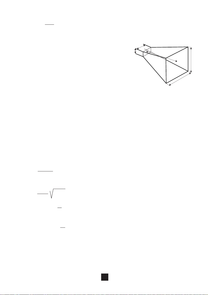
3.3 Gain d'un cornet et atténuation d'espace ................................................................................. 4
3.4 Diagramme de rayonnement d'un cornet .................................................................................. 7
3.5 Polarisation d'un cornet ............................................................................................................. 8
4. CARACTERISTIQUES........................................................................................................................ 9
5. MAINTENANCE .................................................................................................................................. 9
5.1 Nettoyage .................................................................................................................................. 9
5.2 Vérification métrologique........................................................................................................... 9
6. GARANTIE ........................................................................................................................................ 10
7. ANNEXE ............................................................................................................................................ 43
7.1 Vue d'ensemble ....................................................................................................................... 43
7.2 Adaptateur de fixation rapide EASYFIX AFR 100 .................................................................. 43

3
English
............................................................................................................................................
11
Deutsch ........................................................................................................................................... 19
Italiano............................................................................................................................................. 27
Español ........................................................................................................................................... 35
1. PRESENTATION
L'antenne cornet 15 dB ORITEL ANC 100/15 estun composant hyperfréquence étudié pour compléter
le banc didactique ORITEL BDH R100, réalisé en guide d'onde R100/WR90 (8,5 à 9,6 GHz).
Le cornet rectangulaire est un aérien (ou antenne) constitué d'un élément de guide droit, terminé par un
tronçon piramidal, concentre l'énergie rayonnée dans une direction donnée, augmente la portée de
l'émetteur et définit la direction dans laquelle ce trouve un éventuel objectif.
Son adaptation d'impédance, son gain et son diagramme de rayonnement, sont fonction des dimensions
géométriques de son ouverture.
2. DESCRIPTION
Voir § 7.1 et 7.2
➀Fixation rapide EASYFIX
➁Molette de serrage de la fixation rapide EASYFIX
3. UTILISATION
Les manipulations décrites aux § 3.3, 3.4 et 3.5 nécessitent au minimum le montage des composants
mentionnéssur le synoptique figurantdans chacundes paragraphes.Ces composantsfontgénéralement
partie de la fourniture standard du banc didactique de base ORITEL BDH R100.
Pour l'utilisation de ces éléments se reporter à leur notice de fonctionnement respectives.
3.1 Rappel des constituants du banc didactique de base ORITEL BDH-R100
Oscillateur à diode GUNN ORITEL OSG 100 ..................................................................... P01.2753.07
Isolateur à ferrite ORITEL ISO 100...................................................................................... P01.2753.08
Modulateur à diode PIN ORITEL MOD 100......................................................................... P01.2753.09
Atténuateur variable à réglage micromètrique ORITEL ATM 100 ....................................... P01.2753.10
Ondemètre à courbe ORITEL OND 100 .............................................................................. P01.2753.11
Ligne de mesure ORITEL LAF 100...................................................................................... P01.2753.12
Adaptateur d'impédance à 3 plongeurs ORITEL ADZ 100/3............................................... P01.2753.13
Transition guide-coaxial ORITEL TGN 100 .......................................................................... P01.2753.14
Détecteur coaxial ORITEL DEN 100.................................................................................... P01.2753.15
Charge adaptée ORITEL CHG 100 ..................................................................................... P01.2753.16
Plaque court-circuit ORITEL CC 100 ................................................................................... P01.2753.17
Support de guide ORITEL SUP 100 .................................................................................... P01.2753.18

4
■■
■■
■Autres composants (guide d'onde R100/WR90)
Adaptateur fixation rapide EASYFIX ORITEL AFR 100 ...................................................... P01.2753.01
Règle support de banc ORITEL RS 100.............................................................................. P01.2753.03
Milliwattmètre hyperfréquence ORITEL MH 600 ................................................................. P01.2501.01
Sonde à thermocouple ORITEL ST 613 (pour ORITEL MH 600) ....................................... P01.2851.01
Alimentation pour oscillateur à diode GUNN ORITEL CF 204A.......................................Nous consulter
Indicateur de ROS ORITEL IR 205 ...................................................................................... P01.2705.01
Recopie de déplacement ORITEL RD 100 pour ligne de mesure....................................... P01.2753.02
Antenne cornet 15 dB ORITEL ANC 100/15 ....................................................................... P01.2753.04
Coupleur en croix ORITEL CGX 100/20 .............................................................................. P01.2753.05
Iris de couplage 20 et 30 dB ORITEL IRIS 20-30 ............................................................... P01.2753.06
Pour l'utilisation de ces éléments se reporter à la notice de fonctionnement correspondante.
3.2 Utilisation de la fixation rapide EASYFIX
Voir schéma § 7.2
■Disposer les deux éléments à assembler en présentant correctement les plots de centrage ➀en
regard des trous
■Serrer simultanément les deux molettes ➁
3.3 Gain d'un cornet et atténuation d'espace
Les manipulations qui suivent ont pour but de déterminer la valeur du gain d'un ensemble émission-
réception constitué par deux cornets identiques.
Elle sont : -la mesure du rapport d'onde stationnaire du cornet
-la détermination du rapport Pr/Pedes puissances reçue et émise par les cornets et le calcul
du gain.
3.3.1 Rappels théoriques
Les aériens ou antennes sont des éléments rayonnants, ils assurent la transition entre le guide d'onde
et l'espace libre (émission et réciproquement (réception).
Dans le domaine des hyperfréquences, la petitesse de la longueur d'onde permet la réalisation d'une
grande variéré de dispositifs rayonnants : cornets, paraboles, doublets, antennes hélices, ...
Ils s'apparentent en fait aux dispositifs optiques :lentilles, projecteurs, où comme en hyperfréquence on
cherche à concentrer l'énergie dans une direction donnée.
■■
■■
■Gain d'une antenne
Si P0est la puissance émise par une antenne purement théorique qui rayonnerait uniformément dans
toutes les directions (antenne isotrope), le gain d'une antenne de puissance rayonnée P(θ, φ)(θet φ
désignant une direction en coordonnées sphériques) s'écrit :
G(θ, φ)=P(θ, φ)(1)
P0
Le gain permet d'exprimer la concentration d'énergie émise (ou reçue) dans une direction donnée.
On associe aussi à une antenne sa surface équivalente (ou effective).
∑(θ, φ)=G(θ, φ)λ(2)
4 π

5
Pour une antenne théorique isotrope G(θ, φ)= 1 par définition, et donc :
∑(θ, φ)=λ2(3)
4 π
■■
■■
■L'antenne cornet
L'antennecornetde la figure ci-contreest obtenuepar dilatation
progressive de la section d'un guide classique, ce qui a pour
effet d'accroître la surface équivalente, donc le gain de
l'ouverture rayonnante.
On sait en effet, que pour un guide rectangulaire de dimension
a et b, on a : a < λet b ≤a/2.
Sa section ab est donc telle que : ab < λ2/2.
Or compte tenu de la relation (2), le gain ne peut dépasser 2 π.
La longueur axiale l doit par ailleurs être telle que la phase des champs électrique et magnétique soit
constante dans le plan de sortie du cornet; cet condition est obtenue pour :
l≥d2/ 2λ0
Dansla pratique,deux cornets identiquesen dimensions,l'un enémission etl'autreen réception, devront
pour reproduire des conditions de propagation en champ lointain, être espacés d'une distance R telle
que : R ≥2d2/ λ0
Bien qu'assez encombrants, si l'on veut un gain élevé, les cornets sont faciles à adapter au guide
d'excitation et présentent une grande bande de fréquence.
■■
■■
■Expression du gain d'un couple de cornets identiques
Si Peest la puissance emise et Prla puissance reçue, G le gain et R la distance de séparation, la
puissance Prest donnée par la relation suivante :
Pr= PeG2λ02(4)
(4π)2R2
On en tire immédiatement :
G = 4πR Pr / Pe
λ0
Ou encore : GdB = 1(PrdB - PedB) + 10 log (4πR/k0) (5)
2
Par ailleurs l'expression (4) montre très clairement la dépendance en 1/R2du rapport (Pr/Pe)
Pr = (G λ0/ 2π)21 (6)
R2
a
blc
d

6
3.3.2 Mesure du gain d'un cornet
Réaliser le montage de la figure ci-dessous, en respectant les conditions suivantes :
CF 204 IR 205
OSG 100 ISO 100 ATM 100 ATM 100
MOD 100 OND 100
ANC 100/15 ANC 100/15
R
d
TGN 100 + DEN 100
- La distance R entre les deux cornets ANC 100/15 doit-être telle que :
R ≥2d2/ λ0
Il faut donc mesurer λ0à l'ondemètre OND 100 et R avec précision.
Les cornets doivent être parfaitement alignés sur les deux plans (E et H)
- Veiller à éviter tout obstacle dans le champ de rayonnement des cornets.
Procéder de la manière suivante :
- Placer l'atténuateur ATM 100 le plus proche des cornets à la position zéro
Agir sur l'atténuateur ATM 100 situé avant l'ondemètre, afin d'obtenir une lecture correcte sur le
galvanomètre de l'indicateur de ROS IR 205
- Repérer cette indication, soit I1
- Supprimer les deux cornets sans modifier les réglages précédents, le montage devient celui de la
figure suivante :
CF 204 IR 205
OSG 100 ISO 100 ATM 100 ATM 100
MOD 100 OND 100 TGN 100 + DEN 100
- Agir sur l'atténuateur variable ATM 100 situé après l'ondemètre OND 100, de façon à obtenir la même
indication que celle repérée sur l'IR 205 avec le montage précédent, soit I1.
- Lire le rapport des puissances Pr/Peen dB.
- Portercette valeurdansla formule(5) des rappelsthéoriquesainsique les valeursλ0etR déterminées
plus haut.
Le gain est directement obtenu en dB.
Prendre soin d'utiliser des unités cohérentes : λ0en cm et R en cm.

7
3.3.3 Mesure de l'atténuation d'espace
On sait que le rapport Pr/Pedes puissancesreçues et émise par le couple de cornets varie en l/R2
(voir Rappels théoriques).
On peut mesurer cette dépendance en mesurant ce rapport en dB comme indiqué précédemment mais
pour plusieurs valeurs de R, comme ci-dessous :
CF 204 IR 205
OSG 100 ISO 100 ATM 100 ATM 100
MOD 100 OND 100
ANC 100/15 ANC 100/15
R
1
d
TGN 100 + DEN 100
Comparer les résultats obtenus avec l'atténuateur calibré ATM 100 situé après l'ondemètre.
3.4 Diagramme de rayonnement d'un cornet
La mesure du diagramme d'un cornet consiste à déterminer :
- l'amplitude du lobe principal du rayonnement et sa largeur à 3 dB
- l'amplitude des lobes secondaires
Dans le cas d'un cornet rectangulaire, donc à polarisation rectiligne, ces relevés seront effectués dans
les deux plans E et H, en site et en gisement.
3.4.1 Rappels théoriques
Une antenne isotrope est telle qu'un point source émet dans tout l'espace.
Une antenne réelle émet préférentiellement dans certaines directions, où son gain est maximum.
Un diagramme de rayonnement est une représentation de l'intensité du champ ou de la puissance
émise en fonction de l'angle d'observation à distance constante.
On représente le diagramme de rayonnement d'un cornet soit dans le plan E (parallèle au petit côté du
guide), soit dans le plan H (parallèle au plus grand côté du guide).
Le diagramme de rayonnement est constitué de plusieurs lobes, la plus grande partie de la puissance
est concentrée dans le lobe principal. Une antenne est généralement conçue de manière à minimiser la
puissance rayonnée dans les lobes latéraux et dans le lobe arrière, pour augmenter la directivité.
La largeur du lobe principal à 3 dB est l'angle entre deux points où la puissance émise (et donc le gain)
est égale à la moitié de la valeur maximale.

8
3.4.2 Mesure du diagramme de rayonnement d'un cornet
Effectuer le montage ci-dessous :
CF 204 IR 205
OSG 100 ISO 100 ATM 100 ATM 100
MOD 100 OND 100
ANC 100/15 ANC 100/15
R
d
TGN 100 + DEN 100
Prendre les précautions suivantes :
- Respecter la distance minimale entre deux les cornets ANC 100/15 :
R ≥2 d2
λ
- Les cornets doivent rayonner dans un espace libre, c'est à dire loin de tout obstacle métallique, et en
particulier loin du sol.
- Les axes des cornets doivent être parfaitement alignés dans le plan horizontal et le plan vertical.
Vérifier cet alignementen déplaçant légèrement lecornetderéceptionjusqu'àl'obtention d'un maximum
de niveau sur le galvanomètre de l'IR 205.
Procéder de la manière suivante :
- Placer l'atténuateur ATM 100 situé avant l'ondemètre OND 100, à zéro.
- Régler le niveau de sortie sur l'IR 205 jusqu'à l'obtention d'une déviation correcte, en agissant sur
l'atténuateur ATM 100. Repérer l'atténuation A0lue et la déviation D0sur l'IR 205.
- Faire tourner le cornet récepteur d'un angle α1autour d'un axe situé dans le plan d'ouverture du
cornet.
- Ramener l'atténuateur ATM 100 situé après l'ondemètre OND 100 à une atténuation A1jusqu'à
l'obtention du repère D0précédemment lu sur l'IR 205.
- Tourner d'un angle α2, régler l'atténuateur ATM 100 situé après l'ondemètre à A2pour se revenir à
l'indication D0sur l'IR 205.
- Faire ces manipulations pour plusieurs valeurs d'angles de rotation α, de part et d'autre de l'axe du
cornet, et noter pour chaque angle :
∆1= A0- A1
∆2= A0- A2etc...
- Tracer la courbe ∆dB en fonction de a, correspondant au diagramme de rayonnement sur le diagramme
en coordonnées polaires fourni.
3.5 Polarisation d'un cornet
La polarisation du rayonnement peut-être mise en évidence par une simple application de la loi de
MALUS bien connue des opticiens.
L'onde émise est polarisée et rectiligne, puisque le mode de propagation dans le guide est TE10.L'onde
reçueest rectiligne.Sile cornet récepteur tourne autour deson axe longitudinald'un angleα,lapuissance
reçue a pour expression : P = P0cos2α
P0est la puissance reçue sans rotation du cornet récepteur.

9
L'atténuation est alors :
A(dB) =10 log P0= - 10 log (cos2α)
P0cos2α
Appliquer le schéma suivant :
CF 204 IR 205
OSG 100 ISO 100 ATM 100 ATM 100
MOD 100 OND 100
ANC 100/15 ANC 100/15
R
d
TGN 100 + DEN 100
Procéder comme sur la figure ci-dessous :
0
Axe horizontal
a
- Fixer au cornet un rapporteur d'angle et placer le zéro du rapporteur rigoureusement dans l'axe
vertical du cornet.
- Placer l'atténuateur ATM 100 situé après l'ondemètre OND 100, sur sa position zéro.
- Tourner le cornet récepteur d'un angle αet calculer l'atténuation correspondante.
- Repérer l'indication donnée par le galvanomètre de l'IR 205.
- Ramener le cornet récepteur à la position α= 0.
- Atténuer avec l'atténuateur ATM 100 jusqu'à retrouver l'indication précédemment repérée et repérer
l'indication de l'atténuateur.
- Effectuer plusieurs manipulations, en donnant à chaque fois à αdes valeurs différentes.
4. CARACTERISTIQUES
Fréquence : 8,5 à 9,6 GHz
Gain à la fréquence centrale : 15 dB
Largeur du faisceau à F0: 30° dans les deux plans
Guide d'onde : R100
Bride : UBR 100
Masse : 395 g
Dimensions : 132,5 x 80 x 68,5 mm
Compatibilité électromagnétique : Conformité suivant norme NF EN 61326-1, Ed. 98

10
5. MAINTENANCE
Pour la maintenance, utilisez seulement les pièces de rechange qui ont été spécifiées.
Le fabricant ne pourra être tenu pour responsable de tout accident survenu suite à une réparation
effectuée en dehors de son service après-vente ou des réparateurs agréés.
5.1 Nettoyage
Avantmontage descomposants hyperfréquence du banc didactique,s'assurer de l'absencedepoussière
à l'intérieur du guide d'onde.
Attention :
Ne pas utiliser de jet d'air sous pression, sous peine d'endommager certains composants.
Ne pas utiliser de solvant, dépoussiérer avec précautions.
5.2 Vérification métrologique
Comme tous les appareils de mesure ou d’essais, une vérification périodique est nécessaire.
nPourles vérifications et étalonnagesdevosappareils, adressez-vousà nos laboratoiresde métrologie
accrédités COFRAC ou aux agences MANUMESURE.
Renseignements et coordonnées sur demande :
Tél. : 02 31 64 51 43 Fax : 02 31 64 51 09
nRéparation sous garantie et hors garantie.
Adressezvosappareilsà l’une des agences régionales MANUMESURE,agréées CHAUVINARNOUX.
Renseignements et coordonnées sur demande :
Tél. : 02 31 64 51 43 Fax : 02 31 64 51 09
nRéparation hors de France métropolitaine.
Pour toute intervention sous garantie ou hors garantie, retournez l’appareil à votre distributeur.
6. GARANTIE
Notregaranties’exerce,sauf stipulationexpresse,pendant douzemois après la date demise à disposition
du matériel (extrait de nos Conditions Générales de Vente, communiquées sur demande).

11
English
Meaning of the symbol
CAUTION! Consult the operating manual before using the device.
In this operating manual, the instructions preceded by this symbol may cause personal injury or
damage the instrument and installations if they are not scrupulously abided by or carried out.
You have just bought an ORITEL ANC 100/15 (15 dB) horn antenna and we thank you for the interest
you show for our products.
In order to get the best use out of this device:
ncarefully read this operating manual,
nfollow the precautions for use.
PRECAUTIONS FOR USE
nSince the measurements described in this operating manual require a high degree of accuracy, the
measuring bench shall be assembled on a perfectly stable support.
nAll instruments hooked up to the bench and connected to the AC network shall be earthed.
nNo voltage of more than 30 V in relation to the earth shall be present on the bench.
TO ORDER
ORITEL ANC 100/15 (15 dB) horn antenna ...................................................................... P01.2753.04
Delivered with this user's manual
Accessories
ORITEL AFR 100 EASYFIX quick fastening lug adaptor .................................................... P01.2753.01
CONTENTS
1. PRESENTATION............................................................................................................................. 12
2. DESCRIPTION................................................................................................................................12
3. USE ................................................................................................................................................. 12
3.1 Summary of the components making
up the ORITEL BDH R100 basic educational bench.............................................................. 12
3.2 How to use the EASYFIX quick fastening lug......................................................................... 13
3.3 Horn gain and space attenuation ............................................................................................ 13
3.4 Radiation pattern of a horn ..................................................................................................... 16
3.5 Polarisation of a horn .............................................................................................................. 17
4. CHARACTERISTICS ...................................................................................................................... 18
5. MAINTENANCE.............................................................................................................................. 18
5.1 Cleaning................................................................................................................................... 18
5.2 Metrological inspection............................................................................................................ 18
6. GUARANTEE.................................................................................................................................. 18
7. ANNEX ............................................................................................................................................ 43
7.1 General view ............................................................................................................................ 43
7.2 AFR 100 EASYFIX quick fastening lug adaptor ..................................................................... 43

12
1. PRESENTATION
The ORITEL ANC 100/15 (15 dB) horn antenna is a microwave component designed to make complete
the ORITEL BDH R100 educational bench, manufactured using a rectangular waveguide in accordance
with the R100/WR90 standard (covering the frequency range between 8.5 and 9.6 GHz).
The rectangular horn is an antenna made up of a straight waveguide member with a pyramidal section
at the end, concentrates the radiated energy in a given direction, increases the range of the transmitter
and defines the direction in which a possible target is located.
Itsimpedancematching, gain and radiation pattern depend on itsgeometrical dimensions and itsaperture.
2. DESCRIPTION
See § 7.1 and 7.2
➀EASYFIX quick fastening lug
➁Knurled tightening knob for the EASYFIX quick fastening lug.
3. USE
The manipulations described in § 3.3, 3.4 and 3.5 require at a minimum that the components mentioned
on the flow chart appearing in each paragraph be assembled. Generally speaking, these components
are a part of the standard supplies delivered with the ORITEL BDH R100 basic edcational bench.
To use these components, refer to their respective operating manuals.
3.1 Summary of the components making up the ORITEL BDH R100 basic
educational bench
ORITEL OSG 100 Gunn diode oscillator ............................................................................. P01.2753.07
ORITEL ISO 100 ferrite isolator ........................................................................................... P01.2753.08
ORITEL MOD 100 pin diode modulator ............................................................................... P01.2753.09
ORITEL ATM 100 micrometer-adjustable variable attenuator ............................................. P01.2753.10
ORITEL OND 100 curve wavemeter.................................................................................... P01.2753.11
ORITEL LAF 100 measuring line ......................................................................................... P01.2753.12
ORITEL ADZ 100/3 three-screw impedance adaptor .......................................................... P01.2753.13
ORITEL TGN 100 waveguide-to-coax transition element.................................................... P01.2753.14
ORITEL DEN 100 coaxial detector ...................................................................................... P01.2753.15
ORITEL CHG 100 adapted load .......................................................................................... P01.2753.16
ORITEL CC 100 short circuit plate ...................................................................................... P01.2753.17
ORITEL SUP 100 waveguide support ................................................................................. P01.2753.18
■■
■■
■Other components (R100/WR90 standard waveguide)
ORITEL AFR 100 EASYFIX quick fastening lug adaptor .................................................... P01.2753.01
ORITEL RS 100 bench support rail ..................................................................................... P01.2753.03
ORITEL MH 600 microwave milliwattmeter ......................................................................... P01.2501.01
ORITEL ST 613 thermocouple probe (for ORITEL MH 600)............................................... P01.2851.01

13
ORITEL CF 204A power supply unit for Gunn diode oscillator ................................... Please consult us
ORITEL IR 205 SWR indicator............................................................................................. P01.2705.01
ORITEL RD 100 displacement sensor for measuring line................................................... P01.2753.02
ORITEL ANC 100/15 (15 dB) horn antenna ........................................................................ P01.2753.04
ORITEL CGX 100/20 waveguide cross coupler................................................................... P01.2753.05
ORITEL IRIS 20-30 (20 and 30 dB) coupling irises............................................................. P01.2753.06
To use these components, refer to the corresponding operating manual.
3.2 How to use the EASYFIX quick fastening lug
See diagram § 7.2
■Arrange the two components to be assembled, taking care to correctly place the centring studs ➀
opposite the holes
■Simultaneously tighten the two knurled knobs ➁
3.3 Horn gain and space attenuation
Theaimof the followingmanipulationsis to determine the gain valueof a transmission-reception assembly
formed by two identical horns.
These are: - measuring the horn’s standing wave ratio
- determining the Pr/Peratio of the powers received and transmitted by the horns and
calculating the gain.
3.3.1 A summary of the theory on which the experiment is based
Antennas are radiating elements, meaning that they provide the transition between the waveguide and
the free space (transmission and, conversely, reception).
In the field of microwaves, the smallness of the wavelength enables a wide variety of radiating devices
to be made: horns, parabolic antennas, dipoles, helical antennas, etc.
Infact,theyhave certain similaritiesto optical devices:lenses, projectors, through which -asin microwave
technology - the purpose is to concentrate energy in a given direction.
■■
■■
■Antenna gain
If P0is the power emitted by a purely hypothetical antenna radiating uniformly in every direction (isotropic
antenna), the gain of a radiated power P(θ, φ)antenna (θ and φ designating a direction in spherical
coordinates) is written as follows:
G(θ, φ)=P(θ, φ)(1)
P0
The gain enables the concentration of energy emitted (or received) in a given direction to be expressed.
An antenna’s equivalent (or effective) area is also associated with it.
∑(θ, φ)=G(θ, φ)λ(2)
4 π
For a hypothetical isotropic antenna, G(θ, φ)= 1 by definition, and therefore:
∑(θ, φ)=λ2(3)
4 π

14
■■
■■
■The horn antenna
The horn antenna in the figure opposite is obtained by
progressive expansion of a traditional waveguide section, the
effect of which is to increase the equivalent area, and therefore
the radiating aperture gain.
Itisindeedknownthat, forarectangularwaveguideofdimension
a and b, you have: a < λand b ≤a/2.
Its ab section is therefore such that: ab < λ2/2.
When in fact, bearing in mind the equation (2), the gain cannot
exceed 2 π.
The axial length l shall, moreover, be such that the phase of the electric and magnetic fields is constant
in the horn’s output plane; this condition is obtained for:
l≥d2/ 2λ0
Inpractice,inorder to reproduce distantfieldpropagation conditions, two horns with identical dimensions,
one for emission and the other for reception, will have to be spaced out at a distance R such as:
R ≥2d2/ λ0
Although rather cumbersome, if you are looking for a high degree of gain, the horns are easy to adapt to
the excitation waveguide and have a high frequency band.
■■
■■
■Expressing the gain of a couple of identical horns
If Peis the power emitted and Prthe power received, G the gain and R the separation distance, the
power Pris given by the following equation:
Pr= PeG2λ02(4)
(4π)2R2
You immediately get:
G = 4πR Pr / Pe
λ0
Or even: GdB = 1(PrdB - PedB) + 10 log (4πR/k0) (5)
2
Moreover, expression (4) very clearly shows the extent to which the ratio (Pr/Pe) depends on 1/R2.
Pr = (G λ0/ 2π)21 (6)
R2
3.3.2 Measuring the gain of a horn
Set up the assembly in the figure below, abiding by the following conditions:
CF 204 IR 205
OSG 100 ISO 100 ATM 100 ATM 100
MOD 100 OND 100
ANC 100/15 ANC 100/15
R
d
TGN 100 + DEN 100
a
blc
d

15
- The distance R between the two ANC 100/15 horns shall be such that:
R ≥2d2/ λ0
λ0must therefore be measured using the OND 100 wavemeter and R be measured accurately.
The horns shall be perfectly aligned on both planes (E and H).
- Make sure to avoid any obstacle in the horns’ radiation field.
Proceed as follows:
- Place the ATM 100 attenuator which is nearest to the horns in the zero position.
Actuate the ATM 100 attenuator located before the wavemeter, in order to obtain a correct readout on
the galvanometer of the IR 205 SWR indicator
- Identify this indication, i.e. I1
- Do away with the two horns without modifying the previous adjustments; the assembly becomes the
one in the following figure:
CF 204 IR 205
OSG 100 ISO 100 ATM 100 ATM 100
MOD 100 OND 100 TGN 100 + DEN 100
- Actuate the ATM 100 variable attenuator located after the OND 100 wavemeter so as to obtain the
same indication as the one identified on the IR 205 with the previous assembly, i.e. I1.
- Read the power ratio Pr/Pein dB.
- Carry this value over into formula (5) in § 3.3.1 (A summary of the theory on which the experiment is
based) as well as the values λ0and R determined above.
The gain is directly obtained in dB.
Take care to use consistent units: λ0in cm and R in cm.
3.3.3 Measuring space attenuation
We know that the ratio Pr/Peof the powers received and emitted by the two horns varies in l/R2(see the
summary of the theory on which the experiment is based).
This dependence can be measured by this ratio being measured in dB as indicated previously, but for
several R values, as below:
CF 204 IR 205
OSG 100 ISO 100 ATM 100 ATM 100
MOD 100 OND 100
ANC 100/15 ANC 100/15
R
1
d
TGN 100 + DEN 100
Compare the results obtained with the ATM 100 calibrated antenna located after the wavemeter.

16
3.4 Radiation pattern of a horn
Measuring the radiation pattern of a horn consists in determining:
- the amplitude of the main radiation lobe and its width at 3 dB,
- the amplitude of the secondary lobes.
In the case of a rectangular horn, therefore with linear polarisation, these readings will be performed in
the two planes E and H, at elevation angle and relative bearing.
3.4.1 A summary of the theory on which the experiment is based
An isotropic antenna is such that a source point emits into the whole of space.
A real antenna emits preferentially in certain directions, where its gain is maximum.
A radiation pattern is a representation of the field’s strength or the power emitted in relation to the angle
of observation at a constant distance.
The radiation pattern of a horn is represented either in the E plane (parallel to the small side of the
waveguide), or in the H plane (parallel to the largest side of the waveguide).
The radiation pattern is made up of several lobes, with the major part of the power being concentrated in
the main lobe. Generally speaking, an antenna is designed in such a way as to minimise the power
radiated in the side lobes and rear lobe in order to increase directivity.
The width of the main lobe at 3 dB is the angle between two points at which the power emitted (and
therefore the gain) is equal to half the maximum value.
3.4.2 Measuring the radiation diagram of a horn
Set up the assembly below:
CF 204 IR 205
OSG 100 ISO 100 ATM 100 ATM 100
MOD 100 OND 100
ANC 100/15 ANC 100/15
R
d
TGN 100 + DEN 100
Take the following precautions:
- Keep to the minimum distance between the two ANC 100/15 horns:
R ≥2 d2
λ
- The horns must radiate into free space, i.e.far from any metal obstacle, and in particular far from the
ground.
- The axes of the horns shall be perfectly aligned in the horizontal and vertical planes. Check this
alignment by moving the reception horn slightly until you obtain a peak level on the galvanometer of
the IR 205.
Proceed as follows:
- Place the ATM 100 attenuator located before the OND 100 wavemeter at zero.
- Adjust the output level on the IR 205 until you obtain a correct deviation by actuating the ATM 100
attenuator. Identify the A0attenuation read as well as the D0deviation on the IR 205.
- Rotate the receiving horn by an α1angle around an axis located in the horn’s aperture plane.
- Bring the ATM 100 attenuator located after the OND 100 wavemeter back to an A1attenuation until
you obtain the D0identification read previously on the IR 205.

17
- Rotate by an α2 angle, adjust the ATM 100 attenuator located after the wavemeter at A2in order to
come back to the D0indication on the IR 205.
- Carry out these manipulations for several α rotation angle values on either side of the horn and, for
each angle, note down:
∆1= A0- A1
∆2= A0- A2etc.
- Plot the ∆dB curve in acccordance with a, corresponding to the radiation pattern in polar coordinates
provided.
3.5 Polarisation of a horn
Radiation polarisation can be brought to the fore by simply applying the Malus cosine-squared law well-
known to opticians.
The wave emitted is polarised and linear, since the method of propagation in the waveguide isTE10.The
wave received is linear. If the receiving horn rotates around its axis by an αangle, the power received is
expressed as: P = P0cos2α
P0is the received power without the receiving horn rotating.
In that case, attenuation is:
A(dB) =10 log P0= - 10 log (cos2α)
P0cos2α
Apply the following diagram:
CF 204 IR 205
OSG 100 ISO 100 ATM 100 ATM 100
MOD 100 OND 100
ANC 100/15 ANC 100/15
R
d
TGN 100 + DEN 100
Proceed as in the figure below:
0
Horizontal axis
a

18
- Fasten an angle protractor to the horn and place the zero of the protractor strictly in the horn’s vertical
axis.
- Place the ATM 100 attenuator located after the OND 100 wavemeter in its zero position.
- Rotate the receiving horn by an αangle and calculate the corresponding attenuation.
- Identify the indication given by the galvanometer of the IR 205.
- Bring the receiving horn back to the α= 0 position.
- Attenuate using the ATM 100 attenuator until you return to the previously identified indication and
identify the indication on the attenuator.
- Carry out several manipulations, each time giving αdifferent values.
4. CHARACTERISTICS
Frequency: 8.5 to 9.6 GHz
Centre frequency gain: 15 dB
Width of the beam at F0: 30° in both planes
Waveguide: R100
Flange: UBR 100
Weight : 395 g
Dimensions: 132.5 x 80 x 68.5 mm
Electromagnetic compatibility:
Compliance with the NF EN 61326-1 standard, 1998 edition.
5. MAINTENANCE
For maintenance, use only specified spare parts.The manufacturer will not be held responsible
for any accident occuring following a repair done other than by its After Sales Service or approved
repairers.
5.1 Cleaning
Before assembling the educational bench’s microwave components, make sure that no dust is present
inside the waveguide.
CAUTION!
Do not use a pressurised air jet for fear of damaging certain components.
Do not use solvent, and take precautions when dusting.
5.2 Metrological inspection
It is essential that all measuring instruments are regularly calibrated.
For checkingand calibration of your instrument,pleasecontact our accredited laboratories (liston request)
or the Chauvin Arnoux subsidiary or Agent in your country.
nRepairs under or out of guarantee
Please return the product to your distributor.
6. GUARANTEE
Our guarantee is applicable for twelve months after the date on which the equipment is made available
(extract from our General Conditions of Sale, available on request).

19
Deutsch
Bedeutung des Zeichens
Achtung! Lesen Sie die Bedienungsanleitung, bevor Sie das Gerät benutzen.
Werden die Anweisungen in dieser Bedienungsanleitung, denen dieses Symbol vorangestellt ist,
nicht beachtet oder eingehalten, kann es zu Verletzungen von Menschen oder Beschädigungen des
Geräts oder der Installationen kommen.
Wir danken Ihnen für das Vertrauen, dass Sie uns mit dem Kauf dieses Hornantenne 15 dB ORITEL
ANC 100/15 entgegengebracht haben.
Damit die optimale Nutzung des Geräts gewährleistet ist:
nlesen diese Bedienungsanleitung sorgfältig durch,
nbeachten Sie die Sicherheitshinweise.
SICHERHEITSHINWEISE
nDie in dieser Bedienungsanleitung beschriebenen Messungen erfordern eine hohe Präzision, das
Lehrsystem muss auf einem sehr stabilen Träger angebracht sein.
nAlle am Lehrsystem angeschlossenen Geräte, die mit Netzspannung betrieben werden, müssen
geerdet sein.
nAm Lehrsystem darf keine Spannung von mehr als 30 V gegenüber Erde vorhanden sein.
BESTELLANGABEN
Hornantenne 15 dB ORITEL ANC 100/15 ......................................................................... P01.2753.04
Geliefert mit zugehöriger Bedienungsanleitung
Zubehör
Adapter Schnellbefestigung EASYFIX ORITEL AFR 100 ................................................... P01.2753.01
INHALT
1. VORSTELLUNG ............................................................................................................................. 20
2. BESCHREIBUNG ........................................................................................................................... 20
3. VERWENDUNG .............................................................................................................................. 20
3.1 Liste der Bestandteile des Basis-Schulungsplatzes ORITEL BDH-R100 .............................. 20
3.2 Verwendung der EASYFIX-Schnellbefestigung ...................................................................... 21
3.3 Gewinn eines Horns und Raumdämpfung .............................................................................. 21
3.4 Strahlungsdiagramm eines Horns ........................................................................................... 23
3.5 Polarisierung eines Horns ....................................................................................................... 25
4. TECHNISCHE DATEN .................................................................................................................... 26
5. WARTUNG...................................................................................................................................... 26
5.1 Reinigung................................................................................................................................. 26
5.2 Messtechnische Überprüfung ................................................................................................. 26
6. GARANTIE...................................................................................................................................... 26
7. ANLAGE ......................................................................................................................................... 43
7.1 Gesamtansicht ........................................................................................................................ 43
7.2 Schnellbefestigungsadapter EASYFIX AFR 100 .................................................................... 43

20
1. VORSTELLUNG
Die Hornantenne 15 dB ORITEL ANC 100/15 isteinfür das Lehrsystem ORITEL BDH R100 entwickeltes
Mikrowellen-Bauelement in Hohlleitertechnik R100/WR90 (8,5 bis 9,6 GHz).
DasauseinemgeradenFührungselementbestehende,durcheinpyramidenförmigesTeilstückabgeschlossene
Rechteckhorn ist eine Antenne, die die Strahlungsenergie in eine bestimmte Richtung konzentriert, die
Reichweite des Senders erhöht und die Richtung festlegt, in der sich ein eventuelles Ziel befindet.
Seine Impedanzanpassung, sein Gewinn und sein Strahlungsdiagramm hängen von den geometrischen
Abmessungen seiner Öffnung ab.
2. BESCHREIBUNG
Siehe § 7.1 und 7.2
➀Schnellbefestigung EASYFIX
➁Feststellrädchen für die
EASYFIX-Schnellbefestigung
3. VERWENDUNG
Die in § 3.3, 3.4 und 3.5 beschriebenenVorgänge erfordern mindestens den Aufbau der Bauteile, die im
Schaltbildzuden einzelnenParagraphenangegeben sind.DieseBauteile sind im Allgemeinen Bestandteil
der Standardlieferung des Basis-Lehrsystems ORITEL BDH R100.
Hinweise zur Verwendung dieser Elemente finden Sie in den zugehörigen Bedienungsanleitungen.
3.1 Liste der Bestandteile des Basis-Schulungsplatzes ORITEL BDH-R100
GUNN-Oszillator ORITEL OSG 100 .................................................................................... P01.2753.07
Ferrit-Ventil ORITEL ISO 100 ............................................................................................... P01.2753.08
PIN-Modulator ORITEL MOD 100........................................................................................ P01.2753.09
Variables Dämpfungsglied mit Mikrometereinstellung ORITEL ATM 100 ........................... P01.2753.10
Frequenzmesser ORITEL OND 100 .................................................................................... P01.2753.11
Schlitzleitung ORITEL LAF 100 ........................................................................................... P01.2753.12
3-Schrauben-Transformator ORITEL ADZ 100/3................................................................ P01.2753.13
Hohlleiter-Koax-Übergang ORITEL TGN 100 ..................................................................... P01.2753.14
Koaxial-Detektor ORITEL DEN 100 ..................................................................................... P01.2753.15
Hohlleiterabschluss ORITEL CHG 100 ............................................................................... P01.2753.16
Kurzschluss ORITEL CC 100............................................................................................... P01.2753.17
Hohlleiter-Stativ ORITEL SUP 100 ..................................................................................... P01.2753.18
§Weitere Komponenten (Hohlleiter R100/WR90)
Adapter Schnellbefestigung EASYFIX ORITEL AFR 100 ................................................... P01.2753.01
Stützschiene für Lehrsystem ORITEL RS 100 ................................................................... P01.2753.03
Mikrowellen-Milliwattmeter ORITEL MH 600 ....................................................................... P01.2501.01
Sonde mit Thermoelement ORITEL ST 613 (für ORITEL MH 600) .................................... P01.2851.01
Stromversorgung für GUNN-Oszillator ORITEL CF 204A......................... Bitte wenden Sie sich an uns
SWV-Messer ORITEL IR 205............................................................................................... P01.2705.01
Wegaufnehmer ORITEL RD 100 für Schlitzleitung.............................................................. P01.2753.02
Hornantenne 15 dB ORITEL ANC 100/15 ........................................................................... P01.2753.04
Kreuzkoppler ORITEL CGX 100/20 ..................................................................................... P01.2753.05
Kopplungs-Irisblenden 20 und 30 dB ORITEL IRIS 20-30 .................................................. P01.2753.06
Hinweise zur Verwendung dieser Elemente finden Sie in den zugehörigen Bedienungsanleitungen.
This manual suits for next models
1
Table of contents
Languages:
Other Chauvin Arnoux Antenna manuals
Popular Antenna manuals by other brands

Ventev
Ventev M6050060D37202WST quick guide

Advanced Diagnostics
Advanced Diagnostics ADC242 user manual

Hi-Z Antennas
Hi-Z Antennas AL-18 manual

Directive Systems & Engineering
Directive Systems & Engineering DSEDPM144-5LVA manual

KVH Industries
KVH Industries TracVision M9 Replacement instructions

Vivax
Vivax UA-888 user manual