CHD Elektroservis CR78-PGM Guide

7
Model 8-452
ver. 2.1
HARDWARE TESTS AND ADJUSTMENT
© 2017 CHD Elektroserv is

CR78-PGM
Programmer & Controller for Roland CR-78
Model 8-452 ver. 2.1
Copyri ght © 2017 CHD Elektroservis
All rights reserved. No part of this publication may be reproduc ed in any form without written permis sion of CHD Elektroservis .
2
Content
page
A) HW tests . . . . . . . . . . . . . . . . . . . . . . . . . . . . . . . . . . . . . . . . . . . 3
1. Test of display . . . . . . . . . . . . . . . . . . . . . . . . . . . . . . . . . . . . . . . . 3
2. Test of buttons . . . . . . . . . . . . . . . . . . . . . . . . . . . . . . . . . . . . . . . . 3
3. Test of switches . . . . . . . . . . . . . . . . . . . . . . . . . . . . . . . . . . . . . . . 4
4. Test of DIN-SYNC input . . . . . . . . . . . . . . . . . . . . . . . . . . . . . . . . . . . 4
5. Test of MIDI-IN input . . . . . . . . . . . . . . . . . . . . . . . . . . . . . . . . . . . . . 5
6. Test of EXT-CLOCK output . . . . . . . . . . . . . . . . . . . . . . . . . . . . . . . . . 5
7. Test of WRITE output . . . . . . . . . . . . . . . . . . . . . . . . . . . . . . . . . . . . 5
8. Test of START/STOP output . . . . . . . . . . . . . . . . . . . . . . . . . . . . . . . . 6
9. End of tests . . . . . . . . . . . . . . . . . . . . . . . . . . . . . . . . . . . . . . . . . 6
B) Operational system version displaying . . . . . . . . . . . . . . . . . . . . . . . . . . . . 8
C) Adjustment . . . . . . . . . . . . . . . . . . . . . . . . . . . . . . . . . . . . . . . . . . 9
1. Length of Start/Stop pulse . . . . . . . . . . . . . . . . . . . . . . . . . . . . . . . . . . 10
2. Length of Write pulse . . . . . . . . . . . . . . . . . . . . . . . . . . . . . . . . . . . . . 10
This manual in PDF form is available on supplemental CD-ROM or on manufacturer’s web-pages.
Manufacturer :
CHD Elektroservis
Nad kundratkou 27, 19000 Praha 9
Czech Republic
www.chd-el.cz
info
@
chd-el.cz

CR78-PGM
Programmer & Controller for Roland CR-78
Model 8-452 ver. 2.1
Copyri ght © 2017 CHD Elektroservis
All rights reserved. No part of this publication may be reproduc ed in any form without written permis sion of CHD Elektroservis .
3
A) HW TESTS
Operating system of CR78-PGM controller contains routines for checking of functionality of own
hardware circuits. The tests can be processed if the device does not work properly in harness with CR-
78 instrument.
For enter into testing mode, press INSTR and NEXT buttons and hold them pressed [1]. Then
turn the device on – connect supply adapter [2]. After that, all dots are displayed on device’s display.
Now INSTR and NEXT buttons can be depressed.
1. TEST OF DISPLAY
Test of display is launched automatically immediately after entering into testing mode. All dots or
blank area are displayed alternately on all positions of the display (all dots luminous or all dots hidden):
Also functionality of LCD contrast regulator (LCD-CONTR) can be tested during this test (with
LCD-CONTR regulator).
Continue to next test occurs automatically after any of buttons on device’s panel is pressed.
2. TEST OF BUTTONS
Status of each of buttons is displayed as circular symbol on the display. This symbol is blank
before a button is pressed and it will be filled after a button pressing.

CR78-PGM
Programmer & Controller for Roland CR-78
Model 8-452 ver. 2.1
Copyri ght © 2017 CHD Elektroservis
All rights reserved. No part of this publication may be reproduc ed in any form without written permis sion of CHD Elektroservis .
4
W = WRITE / PLAY INSTRUMENT
N = NEXT / START – STOP
I = BEAT / TEMPO INCREMENT
D = BEAT / TEMPO DECREMENT
Continue to next test occurs automatically after all four buttons are pressed.
3. TEST OF SWITCHES
Status of SYNC and MODE switches is displayed during this test. Actual position of some of
switches is shown under abbreviation of corresponding switch.
For continue to next test, NEXT button must be pressed.
4. TEST OF DIN-IN INPUT
The display shows actual status of DIN-SYNC bus signals on DIN-IN input. Symbol “C” is used
for Clock signal and symbol “R“ is used for Run signal. Signals Reset and Fill are not used in the
controller.
Signals can be incoming to DIN-IN input from any DIN-SYNC transmitter or external source of
DC voltage (from 4 to 5 volts) can be used – see picture:
For continue to next test, NEXT button must be pressed.

CR78-PGM
Programmer & Controller for Roland CR-78
Model 8-452 ver. 2.1
Copyri ght © 2017 CHD Elektroservis
All rights reserved. No part of this publication may be reproduc ed in any form without written permis sion of CHD Elektroservis .
5
5. TEST OF MIDI-IN INPUT
Display shows actual status of Transport MIDI commands received from MIDI transmitter on
MIDI-IN input:
Default status (no received MIDI command) is displayed as dashes.
Symbol “CLK” is shown on left side of the display every time when Clock MIDI
command (status byte F8h) is received on MIDI input. The symbol is shown for
approx. 0,2 sec.
On right side of the display, symbol of last received
Transport MIDI command is shown. The symbol is
“STR“ for START command (status byte FAh) or
“CON“ for CONTINUE command (status byte FBh) or “STP“ for STOP command (status byte FCh).
For continue to next test, NEXT button must be pressed.
6. TEST OF EXT-CLOCK OUTPUT
Status of the output can be set with INCREMENT and DECREMENT buttons. Actual status is
shown on the display simultaneously. +5V voltage level is on EXT-CLOCK output in “ON” status and
0V voltage level is on the output in “OFF” status.
Status of the output can be checked with DC voltmeter or with help of testing circuit – see
picture:
For continue to next test, NEXT button must be pressed.
7. TEST OF WRITE OUTPUT
Status of the output can be set with INCREMENT and DECREMENT buttons. Actual status is
shown on the display simultaneously. Contacts of WRITE output are opened in ON status and the
contacts are connected in OFF status - the output works as NC type switch.

CR78-PGM
Programmer & Controller for Roland CR-78
Model 8-452 ver. 2.1
Copyri ght © 2017 CHD Elektroservis
All rights reserved. No part of this publication may be reproduc ed in any form without written permis sion of CHD Elektroservis .
6
Status of the output can be checked with short-circuit tester or with help of testing circuit – see
picture:
For continue to next test, NEXT button must be pressed.
8. TEST OF START / STOP OUTPUT
Status of the output can be set with INCREMENT and DECREMENT buttons. Actual status is
shown on the display simultaneously. Contacts of START / STOP output are opened in ON status and
the contacts are connected in OFF status - the output works as NC type switch.
Status of the output can be checked with short-circuit tester or with help of testing circuit – see
picture:
For continue, NEXT button must be pressed.
9. END OF TESTS
All available tests are executed now. Display shows info:
For continue, NEXT button must be pressed.

CR78-PGM
Programmer & Controller for Roland CR-78
Model 8-452 ver. 2.1
Copyri ght © 2017 CHD Elektroservis
All rights reserved. No part of this publication may be reproduc ed in any form without written permis sion of CHD Elektroservis .
7
Now, operational system version number and date are displayed for about 3 seconds.
Then the device automatically comes to normal working mode.
If no error occurs during testing procedures, the device is fully functional and it should to work
with CR-78 drum machine correctly. If the device doesn’t work with CR-78 in this case, some mistake
can be in used interconnecting cables or in CR-78 drum machine.
If any hardware error occurs during testing procedures, the device must be repaired in
specialized workshop.

CR78-PGM
Programmer & Controller for Roland CR-78
Model 8-452 ver. 2.1
Copyri ght © 2017 CHD Elektroservis
All rights reserved. No part of this publication may be reproduc ed in any form without written permis sion of CHD Elektroservis .
8
B) OPERATIONAL SYSTEM VERSION DISPLAYING
Complete tests need not to be executed if only version of operational system of the device is
requested. In that case, press INCREMENT button and hold it [1]. Then turn the device on – connect
supply adapter [2]. After that, operational system version number is shown on display for about 3
seconds and then the device comes to normal working mode.
After that, operational system version number and date are shown on display for about 3
seconds.
Then the device automatically comes to normal working mode.

CR78-PGM
Programmer & Controller for Roland CR-78
Model 8-452 ver. 2.1
Copyri ght © 2017 CHD Elektroservis
All rights reserved. No part of this publication may be reproduc ed in any form without written permis sion of CHD Elektroservis .
9
C) ADJUSTMENT
The device enables user adjustment of length of pulses generated on START/STOP and WRITE
outputs. Sometimes this can be necessary – if the CR-78 instrument doesn’t react correctly to Start /
Stop or Write commands. This is mostly caused by input circuits of the CR-78. The instrument is very
old and some components alter their parameters over time – especially electrolytic capacitors. In that
case, longer START/STOP or/and WRITE pulses have to be used for such instrument.
Remark: Adjustment of START/STOP and WRITE pulses is available only in versions of
operating system 2.10 and higher. So check version of your device (see chapter B - Operational
system version displaying) please before you will try to change the pulses length.
First, unscrew four self-tapping screws from bottom side of the CR78-PGM controller and
remove the bottom cover from the device:
Now you can see printed circuit board of the controller:
A B C D
PROCESSOR (ON OPPOSITE SIDE)
20 1
21 40
REMOVE SOLDER MASK HERE
SOLDER PADS
CR78-PGM
Programmer & Controller for Roland CR-78
Model 8-452 ver. 2.1
Copyri ght © 2017 CHD Elektroservis
All rights reserved. No part of this publication may be reproduc ed in any form without written permis sion of CHD Elektroservis .
10
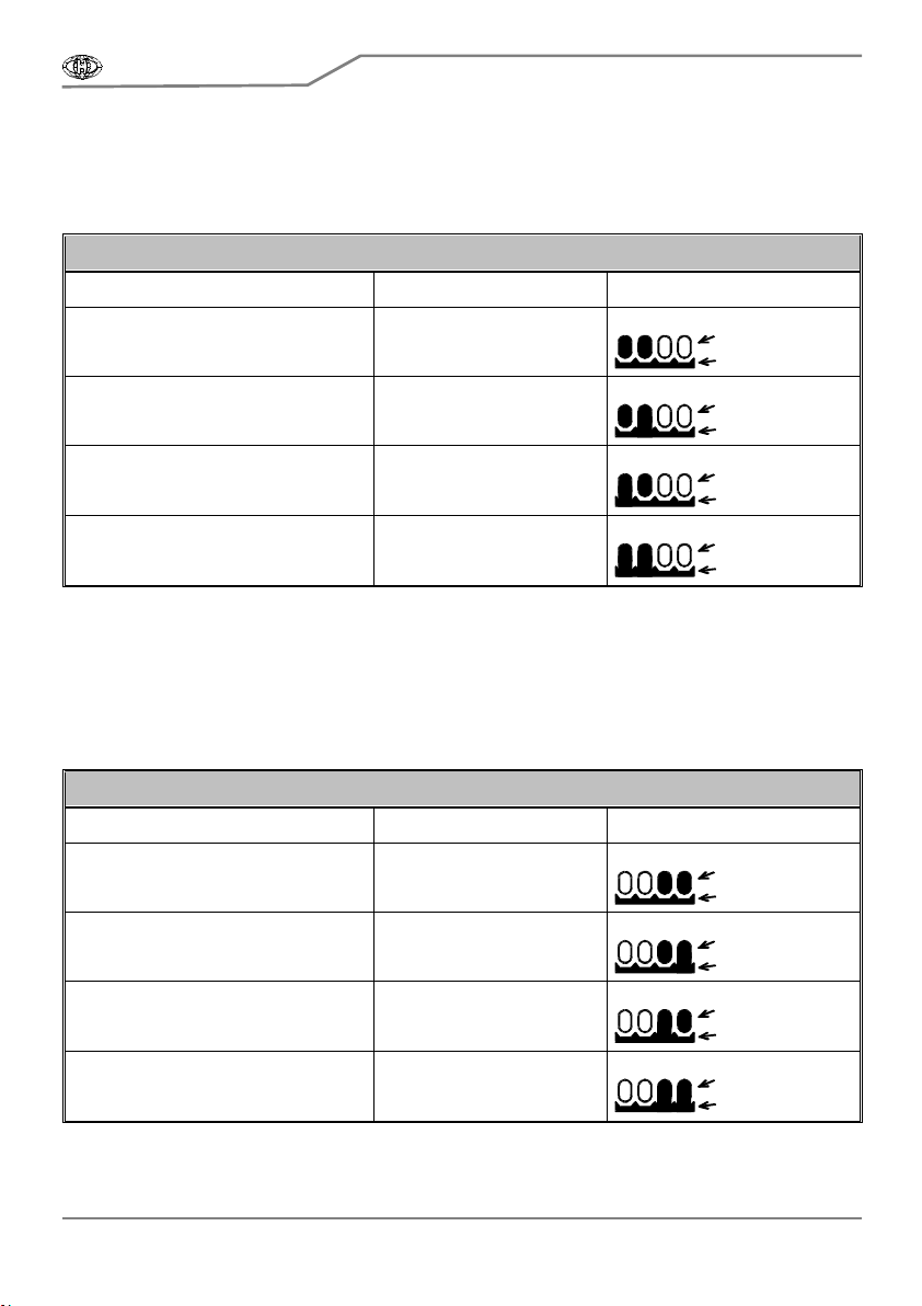
1. LENGTH OF START/STOP PULSE
Remove the green solder mask from the ground plate near the solder pads A and B. Then
connect solder pads A (pin Nr. 17 of processor) and B (pin Nr. 16 of processor) to ground plate with
help of a drop of tin. Use only one or both pads in dependence on requested length of the pulse.
Start / Stop Pulse adjustment
A and B pads status Start/Stop Pulse Length Connection
Both A and B pads not grounded 50 ms (factory setting)
A
BCD
GND
PADS
A pad not grounded, B pad grounded 75 ms
A
BCD
GND
PADS
A pad grounded, B pad not grounded 100 ms
A
BCD
GND
PADS
Both A and B pads grounded 125 ms
A
BCD
GND
PADS
2. LENGTH OF WRITE PULSE
Remove the green solder mask from the ground plate near the solder pads C and D. Then
connect solder pads C (pin Nr. 15 of processor) and D (pin Nr. 14 of processor) to ground plate with
help of a drop of tin. Use only one or both pads in dependence on requested length of the pulse.
Write Pulse adjustment
C and D pads status Write Pulse Length Connection
Both C and D pads not grounded 20 ms (factory setting)
A
BCD
GND
PADS
C pad not grounded, D pad grounded 40 ms
A
BCD
GND
PADS
C pad grounded, D pad not grounded 60 ms
A
BCD
GND
PADS
Both C and D pads grounded 80 ms
A
BCD
GND
PADS

CR78-PGM
Programmer & Controller for Roland CR-78
Model 8-452 ver. 2.1
Copyri ght © 2017 CHD Elektroservis
All rights reserved. No part of this publication may be reproduc ed in any form without written permis sion of CHD Elektroservis .
11
NOTES:
Manufacturer :
CHD Elektroservis
Nad kundratkou 27, 19000 Praha 9
Czech Republic
www.chd-el.cz
info
@
chd-el.cz

7
Other manuals for CR78-PGM
1
Table of contents


