CHD Elektroservis CRX8-M User manual

7
Model 8-449
ver. 1.0
INSTALLATION MANUAL FOR CR-78
© 2013 CHD Elektroserv is
CRX8-M
MIDI Interface for Roland CR-68 / CR-78
Model 8-449 ver. 1.0
Copyright © 2013 CHD Elektroservis . All rights reserved.
No part of this publicat ion may be reproduced in any form wit hout t he written permission of CHD Elektroservis.
2
Content
page
1. General information . . . . . . . . . . . . . . . . . . . . . . . . . . . . . . . . . . . 3
1.1. Parts of MID I interface . . . . . . . . . . . . . . . . . . . . . . . . . . . . . . . . . . 3
2. MID I interface installati on . . . . . . . . . . . . . . . . . . . . . . . . . . . . . . . . 4
2.1. Removing of i nstrument’s cover . . . . . . . . . . . . . . . . . . . . . . . . . . . . . 5
2.2. Modific ation of instrument’s rear panel . . . . . . . . . . . . . . . . . . . . . . . . . 4
2.2.1. Panel removing . . . . . . . . . . . . . . . . . . . . . . . . . . . . . . . . . . . . . 4
2.2.2. D ri lling of holes for interface board, MIDI s oc kets and switc h . . . . . . . . . . . . . . 5
2.2.3. Montage of i nterface board, MID I sockets and swi tch . . . . . . . . . . . . . . . . . . 5
2.3. Replacement of i ndication LED . . . . . . . . . . . . . . . . . . . . . . . . . . . . . 8
2.4. Audio-cable installation . . . . . . . . . . . . . . . . . . . . . . . . . . . . . . . . . 9
2.5. Flat cable of control signals installation . . . . . . . . . . . . . . . . . . . . . . . . . 9
2.6. Flat cable of tri gger si gnals installation . . . . . . . . . . . . . . . . . . . . . . . . . 15
2.7. Finishing of installation . . . . . . . . . . . . . . . . . . . . . . . . . . . . . . . . . 19
3. Tip to C R-78 instrument modi fic ati on . . . . . . . . . . . . . . . . . . . . . . . . . . 20
Thi s manual in PD F form is available on supplemental C D -RO M or on manufacturer’s web-pages .
Manufacturer :
CHD Elektroserv is
Nad kundratkou 27, 19000 Praha 9
Czech Republic
info@chd -el.cz
www. c h d - e l . c z
CRX8-M
MIDI Interface for Roland CR-68 / CR-78
Model 8-449 ver. 1.0
Copyright © 2013 CHD Elektroservis . All rights reserved.
No part of this publicat ion may be reproduced in any form wit hout t he written permission of CHD Elektroservis.
3
1. GENERAL INFORMATION
C RX 8-M MID I interfac e enables full i ntegration of Roland CR-68 and CR-78 instruments to MIDI
system. The Interface affects s ome functional blocks of the instrument which then can be controlled
with a help of MIDI commands. All original functions of the instrument s tay unc hanged and the
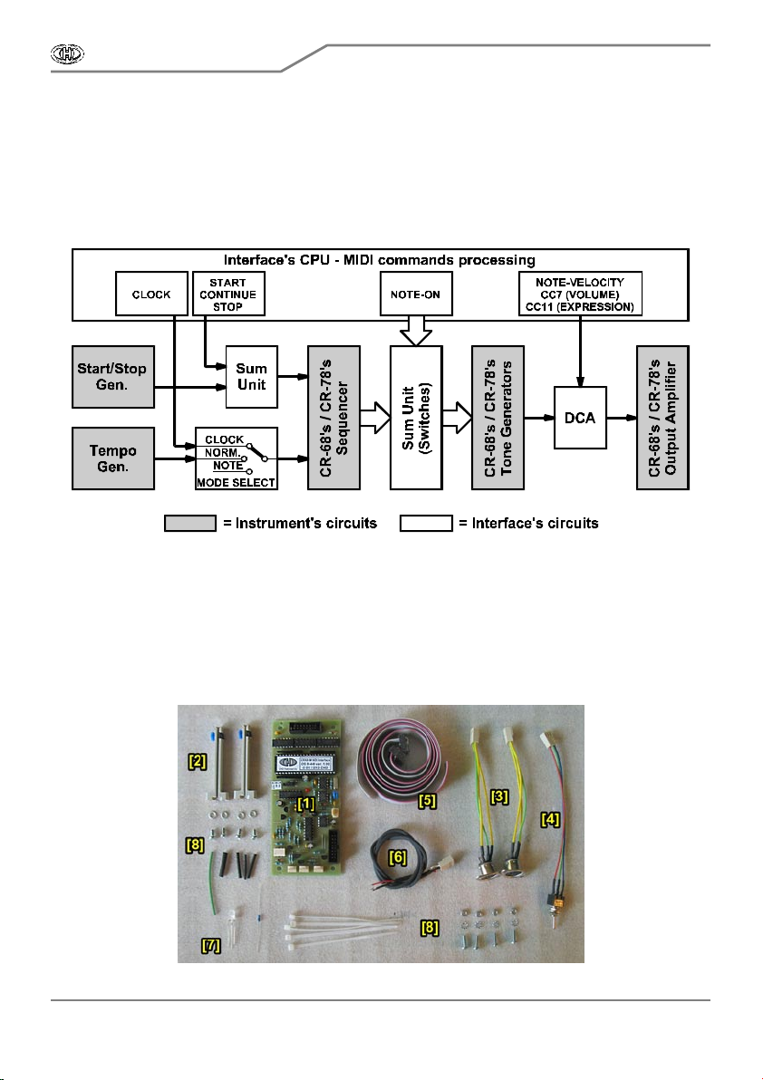
instrument still can be used the same way as before the interface installation. Pic. 1.1 shows functional
bloc k diagram of the instrument after the interface installation.
Pic. 1.1 – Connection to the instrument
1.1. PARTS OF MIDI IN TER FAC E
The deli very of MID I interface kit contents all parts nec es sary for installation i nc . all support and
coupling elements. Par ts of deli very are also manuals for installati on, handling and i nterfac e’s Sys Ex
communication and CD-ROM with support software. Please check if the delivery is complete before
the installation (see pic. 1.1.1).
P ic. 1.1.1 – Parts of the interface kit
CRX8-M
MIDI Interface for Roland CR-68 / CR-78
Model 8-449 ver. 1.0
Copyright © 2013 CHD Elektroservis . All rights reserved.
No part of this publicat ion may be reproduced in any form wit hout t he written permission of CHD Elektroservis.
4
The C RX8-M i nterfac e k it delivery c ontents :
[1] MID I interface board [8] C oupling elements: 4x screw M3x6, 4x screw
[2] 2x S upport guide for PC B M3x10, 4x washer φ3,2, 4x tooth lock washer
[3] 2x B unched cables with DIN-5 socket φ3,2, 4x nut M3, 5x plas tic stri pe, insulation tube
[4] Bunched cables with tumbler switch φ1 mm, 3x heat-s hrink insulation tube φ2 mm,
[5] 2x Flat c able wi th connector heat-shrink insulati on tube φ4 mm
[6] Shi elded audio-c able with connec tor [9] D oc umentation: C D -ROM, manuals in printed form
[7] Bi-color LE D, resi stor 1MΩ
2. MID I IN TE RFACE IN STALLATION
Montage of all parts of the interface into Roland CR-68 / CR-78 instrument is a little more
complicated but no major problem should occur if all instructions indi cated in i ns tallation manual are
kept. Proc edur es of interface’s par ts installation are des cribed in detail in c hapters below. Please k eep
these instructions exactly so that the instrument isn’t damaged.
Attention ! Disconnect the instrument from the mains prior to the installat ion.
Otherwise, there is a risk of the electric shock!
The producer is not responsible for any eventual mechanical or electrical dam age of
the CR-68 / CR-78 instrument caused by the infringement of the described installation
procedure or by careless manipulation during the installation of the MIDI interface!
2.1. REMOVING OF INSTRUMENT’S COVER
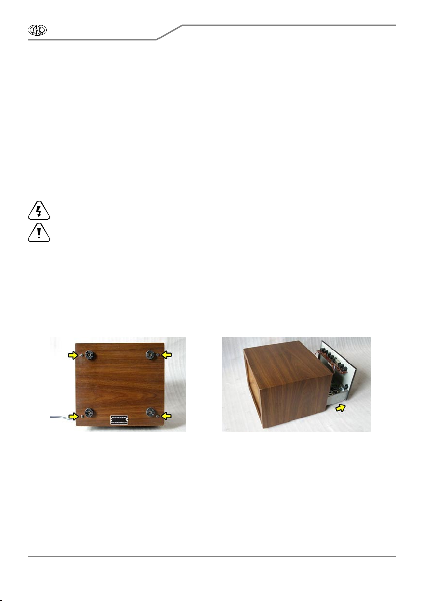
a) Uns crew four s crew s on bottom si de of the ins trument c over ( pi c. 2.1.1) Keep the sc r ews .
They will be used agai n after the MIDI kit i nstallation.
b) C arefully extr ude the ins tr ument’s chas si s bac kwar d from the cover (pic. 2.1.2).
Pic. 2.1.1 Pic. 2.1.2
2.2. MODIFICATION OF IN STR U MENT’S R EAR P AN EL
MIDI sockets, tumbler switch and interface’s board will be placed on rear panel of the instrument.
For easier montage of these elements, it is convenient to remove the panel from the instrument.
2.2.1. PAN EL RE MOVIN G
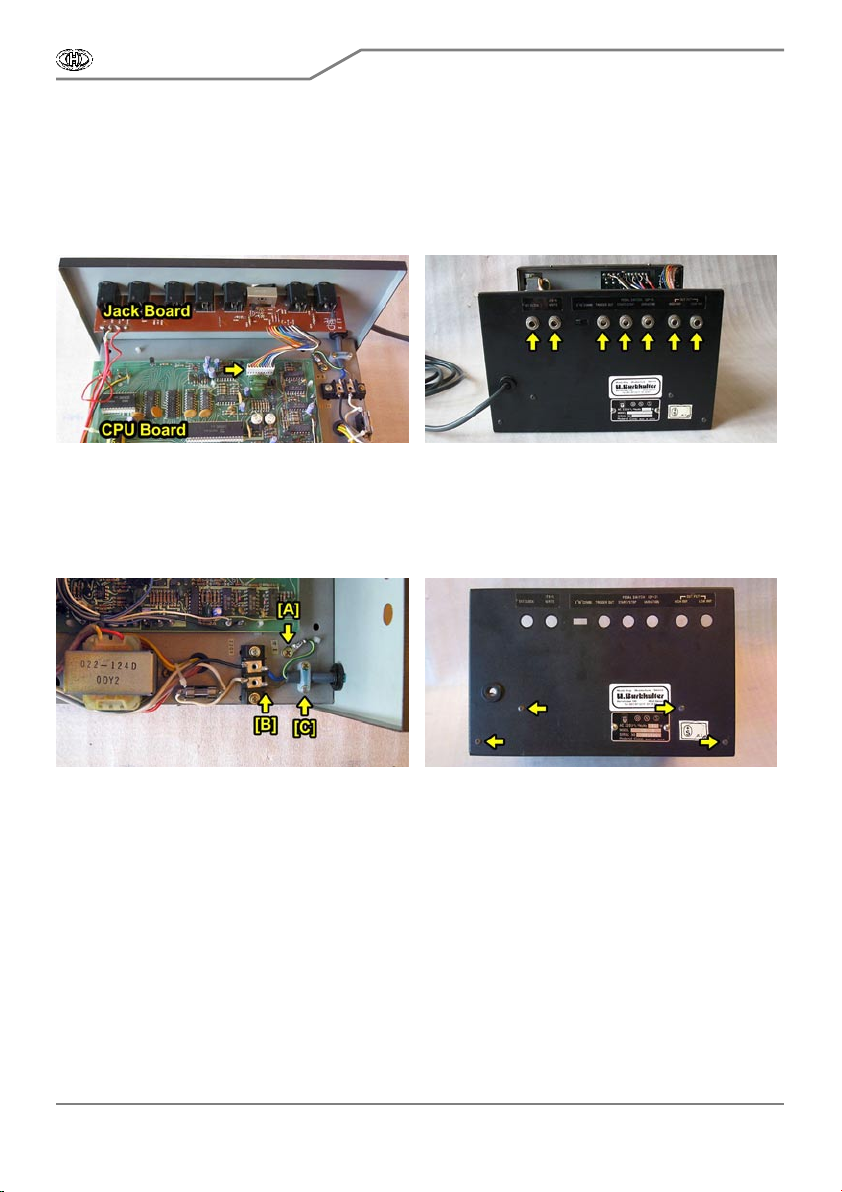
a) D is connect flat connec tor of bunc hed cables leading from J ac k connec tors board (pic .
2.2.1.1). This is valid only for ins truments with s er ial number s from 821051, older instruments have not
this connector.
CRX8-M
MIDI Interface for Roland CR-68 / CR-78
Model 8-449 ver. 1.0
Copyright © 2013 CHD Elektroservis . All rights reserved.
No part of this publicat ion may be reproduced in any form wit hout t he written permission of CHD Elektroservis.
5
b) Unscrew nuts of Jack connectors on instrument’s rear panel (pic. 2.2.1.2). Keep the nuts and
ins ulating was hers . They will be used again after the MID I ki t i ns tallation. Remove the J ac k board
(label OP -104A) fr om the panel and put it asi de car efully so that other cables soldered to the board
would not be damaged.
Note.: Two boards (label OP104 and OP129) are used in instruments with serial numbers up to
780699 – both boards need to be removed.
Pic. 2.2.1.1 Pic. 2.2.1.2
c) Unmount mai ns cable (pi c. 2.2.1.3) - uns crew earth s older lug from i ns trument’s c hass is [A],
uns older c able wi res from terminal plate [B], unfasten c atch clamp [C ] and pull the cable out.
d) Unsc rew four screws on instr ument’ s rear panel (pic . 2.2.1.4) – now the panel is freed. Keep
the sc rew. They will be used again after the MIDI kit installation.
Pic. 2.2.1.3 Pic. 2.2.1.4
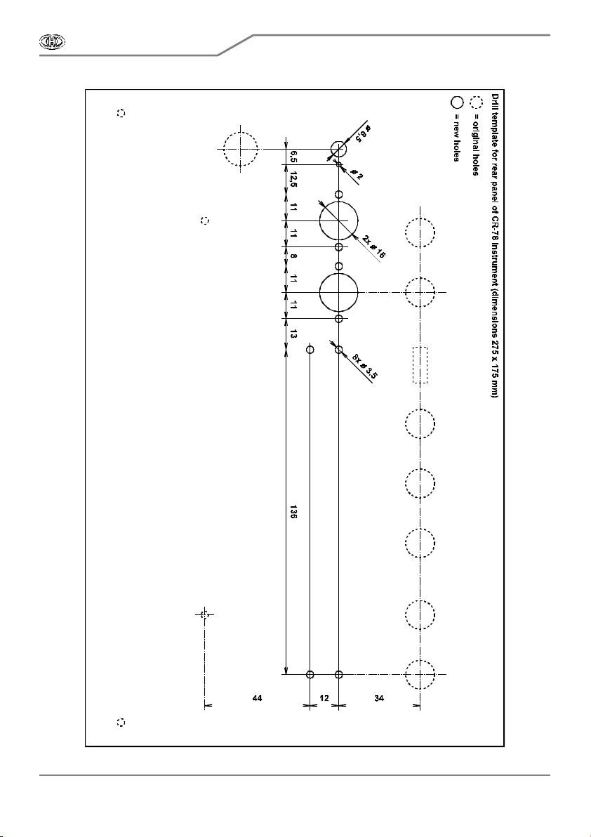
2.2.2. D RILLING OF H OLE S FOR IN TE RFACE B OARD , MID I SOCK ETS AN D SWITCH
a) It is necessary to drill total of 12 holes to instrument’s rear panel ( 1x φ 2 mm, 8x φ 3,5 mm, 1x φ
6,5 mm and 2x φ 16 mm) as shown on pic. 2.2.2.1. For easier designation of centers of new holes, it i s
convenient to use drill template in s cale 1:1 (template i n P DF form is part of documentati on on
supplemental C D-ROM). Put the template to rear panel (from outer s ide) and c opy pos itions of centers
of new holes to the panel with help of s criber or c enter punch.
b) Drill all necessary holes. Use sharp drills with required diameters. Work carefully so that
surface of the panel is not damaged dur ing drilling! C lean the edge of all holes with small rasp or with
poi nt of bigger drill after drilling.
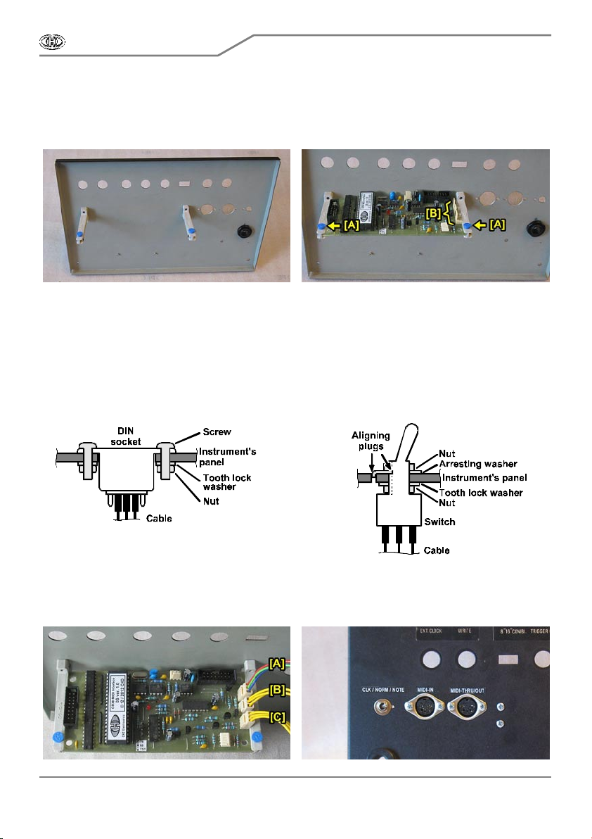
2.2.3. MON TAGE OF IN TER FAC E B OAR D , MID I SOC K ETS AND S WITC H
a) P ut plas tic guide s uppor ts of the interfac e’ s board to insi de of the panel so that gri ps of detent
pins of the supports were upwards and screw the supports to the panel (pi c. 2.2.3.1).
CRX8-M
MIDI Interface for Roland CR-68 / CR-78
Model 8-449 ver. 1.0
Copyright © 2013 CHD Elektroservis . All rights reserved.
No part of this publicat ion may be reproduced in any form wit hout t he written permission of CHD Elektroservis.
6
P ic. 2.2.2.1
CRX8-M
MIDI Interface for Roland CR-68 / CR-78
Model 8-449 ver. 1.0
Copyright © 2013 CHD Elektroservis . All rights reserved.
No part of this publicat ion may be reproduced in any form wit hout t he written permission of CHD Elektroservis.
7
b) Unclog detent pins on supports by pressing of grips ([A] on pic. 2.2.3.2) and intromit interface
board into the supports so that triad of connectors with locks is pointed at holes for MIDI sock ets and
swi tch ( [B ] on pi c. 2.2.3.2). Then fix the interfac e board by pulling of grips - detent pins must click into
detent holes in the i nterfac e board.
P ic. 2.2.3.1 Pic. 2.2.3.2
c ) Get flat connec tors of MIDI cables thr ough the holes with φ 16 mm (from outsi de of panel) and
insert DIN sockets of the cables into the holes fully. Both MIDI bunched cables are identical and they
can be s wapped.
d) Fix DIN sockets to the panel using screws M3, tooth lock washers φ 3,2 mm and nuts M3 from
the inter face ac cess ories (pi c. 2.2.3.3) .
e) Insert tumbler switch into hole with φ 6,5 mm (from inside of panel) and fix it using nuts and
washers (pic. 2.2.3.4). Orientation of the switch gives washer with aligning plugs – it assures that the
switch can’t be mounted contrarywise.
P ic. 2.2.3.3 Pic. 2.2.3.4
f) Plug connectors of bunc hed cables of MID I sockets and s witch to inter fac e board ( pic . 2.2.3.5)
– back connector is for the switch [A], middle is for MID I input [B] and fore is for MIDI output [C].
Orientation of the connec tors is unambiguous ly gi ven by the loc k and they can’t be flipped.
Pic. 2.2.3.5 Pic. 2.2.3.6
CRX8-M
MIDI Interface for Roland CR-68 / CR-78
Model 8-449 ver. 1.0
Copyright © 2013 CHD Elektroservis . All rights reserved.
No part of this publicat ion may be reproduced in any form wit hout t he written permission of CHD Elektroservis.
8
g) It is suitable to label the DIN sockets and tumbler switch – for example, with self-adhes ive foil
glued near to the s oc kets and s witc h on panel of the instrument (pic. 2.2.3.6).
h) Leave rear panel unmounted so that easy access ibili ty to instrument’ printed circuits boards i s
kept during next procedures of installation.
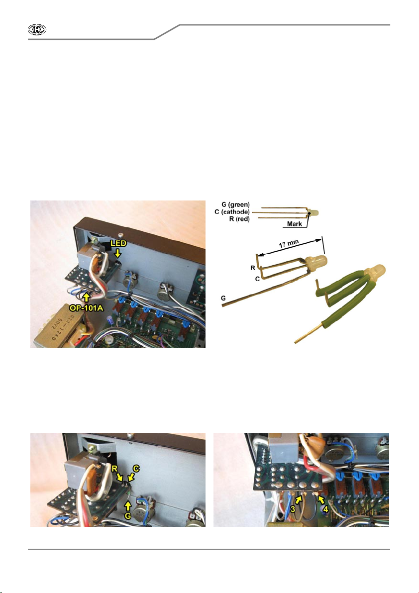
2.3. R EPLACE MENT OF IND IC ATION LED
a) Remove ori ginal LED fr om board (label OP-100A) on front panel of the instrument (pic. 2.3.1).
Note.: This board has label OP100 in instruments with serial number up to 780699. Operating
sequence is the same for both types of the board.
b) Hold leads of the LED with a tweezers and after their unsolder ing, pull the LED from hole i n
sub-panel.
c ) A dapt leads of bicolour LE D from the interface access or y as shown on pi c. 2.3.2. P lac e
ins ulating tubes on leads of the LE D (pic. 2.3.2).
Pic. 2.3.1 Pic. 2.3.2
d) Insert bicolour LED to hole in sub-panel and front panel of the instrument so that its straight
lead was on the right – out of OP- 101A board. Ins er t bent leads R and C to freed holes in OP -100A
board and solder them (pic. 2.3.3).
e) Swap wires Nr. 3 and 4 connected to OP-100A board. Unsolder both wires and the solder the
blac k wire to s oldering pad Nr. 4 (r ight terminal pad on the board) and the brown wire to soldering pad
Nr. 3 (pic. 2.3.4).
Pic. 2.3.3 Pic. 2.3.4

CRX8-M
MIDI Interface for Roland CR-68 / CR-78
Model 8-449 ver. 1.0
Copyright © 2013 CHD Elektroservis . All rights reserved.
No part of this publicat ion may be reproduced in any form wit hout t he written permission of CHD Elektroservis.
9
2.4. AUDIO-CABLE INSTALLATION
a) Free end of the audio-cable (shielded cable from the interface accessory) will be connected to
solder ing pads on potentiometer board (label OP-103A) on i ns trument’s front panel (pic . 2.4.1).
b) Uns older hot wire of red shielded c able fr om soldering pad Nr. 1 from the potentiometer board
(pic. 2.4.2).
P ic. 2.4.1 Pic. 2.4.2
c) Place heat-shrink insulation tube φ 2 mm (from the interfac e ac cess ory) on white wire of audio-
cable and solder white wire freed from the board to it.
d) Isolate the connection with the insulation tube and heat it (wi th a hot-flue pis tol for example)
until it shri nks ti ghtly to the cables (obr. 2.4.3).
e) Solder red wire of the audio-cable to freed soldering pad Nr. 1 on potentiometer board (pic.
2.4.4).
f) Solder shielding of audio-cable to ulterior soldering pad Nr. 9 to which shielding of or iginal red
shielded cable is already connected (pic. 2.4.4).
P ic. 2.4.3 Pic. 2.4.4
2.5. FLAT CABLE OF CONTROL SIGNALS INSTALLATION
Use one of flat 16-wir e cable from the interface acc es sory as c able of control signals – both
deli vered flat cables are identic al and they c an be s wapped.
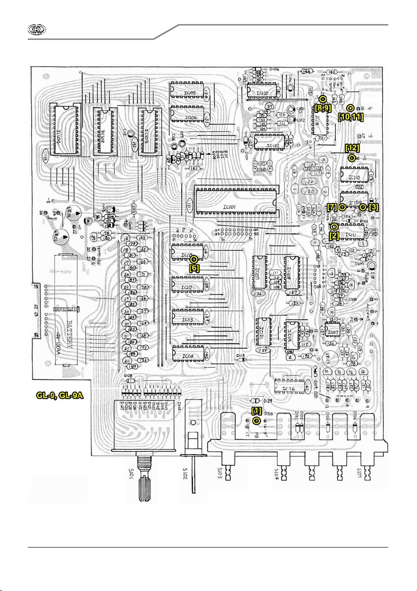
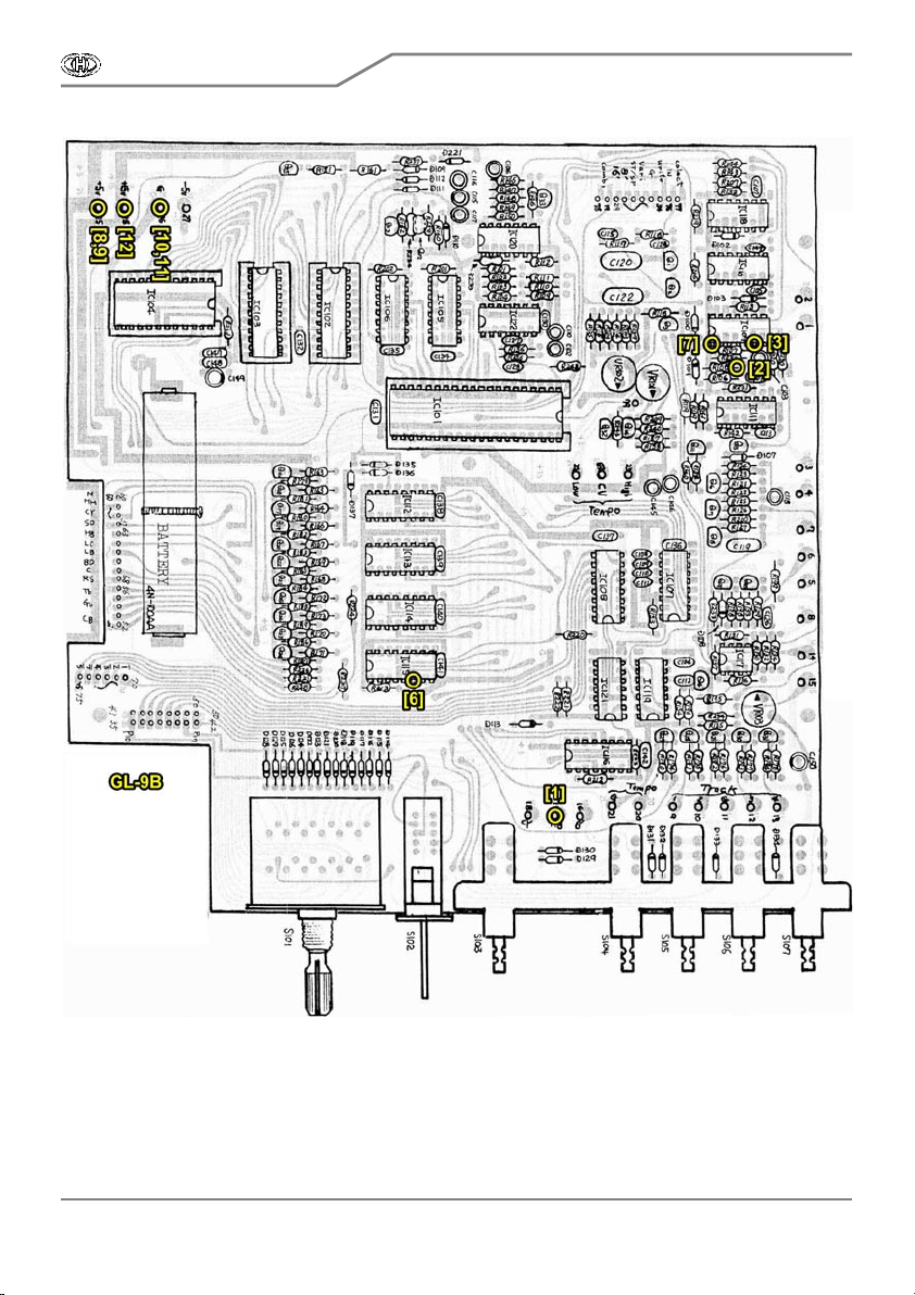
Most of wires of the cable will be connected to CPU board of the instrument. There are three
versions of C PU board - with label GL-9 (instruments with serial number up to 780699) , G L-9A
(instruments with seri al number from 780700 to 821050) and GL-9B (i nstruments with ser ial number
from 821051). GL-9 and GL-9A boards are almost identical (pic. 2.5.1a), a differences are only in
details irrelevant for control signals cable installation. GL-9B board is smaller and it has a different
plac ement of c omponents (pi c. 2.5.1b).
CRX8-M
MIDI Interface for Roland CR-68 / CR-78
Model 8-449 ver. 1.0
Copyright © 2013 CHD Elektroservis . All rights reserved.
No part of this publicat ion may be reproduced in any form wit hout t he written permission of CHD Elektroservis.
1
0
Pic. 2.5.1a
CRX8-M
MIDI Interface for Roland CR-68 / CR-78
Model 8-449 ver. 1.0
Copyright © 2013 CHD Elektroservis . All rights reserved.
No part of this publicat ion may be reproduced in any form wit hout t he written permission of CHD Elektroservis.
11
Pic. 2.5.1b
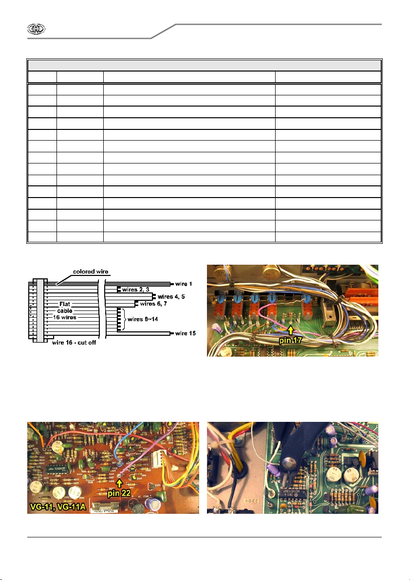
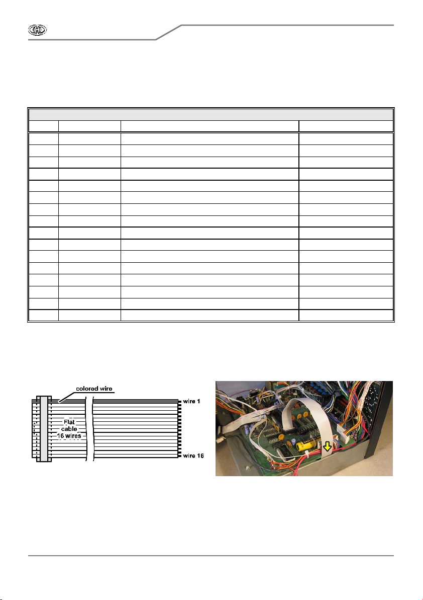
S plit up free end of the c able (by rippi ng or cutti ng) to indi vidual wires and adapt their lengths as
nec es sary during the cable i ns tallation. Wire Nr. 1 ( terminal) is signed with red color. C ut out wire Nr .
16 (the other terminal - uns igned) entirely. It i s not used in C R-78 instrument (pic. 2.5.2). Stripe ends of
wires Nr. 1 to 15 in length about 2 mm and tin them.
Particular wires of control signals cable will be connected in ac cordance with table 1 and pic .
2.5.1.
CRX8-M
MIDI Interface for Roland CR-68 / CR-78
Model 8-449 ver. 1.0
Copyright © 2013 CHD Elektroservis . All rights reserved.
No part of this publicat ion may be reproduced in any form wit hout t he written permission of CHD Elektroservis.
1
2
Table 1 – Wires of flat cable of control signals connection
Wire Signal Point for connection Remarks
1 MB-IN C PU board, w ire-wrapping tip Nr. 17 ( “MB“) C olored wir e
2 S/S-RST CPU board, lead of R108 resistor
3 S /S-SET C PU board, lead Nr. of 6 IC109 C ut the IC lead from board !
4 LED -R OP-110 board, s oldering pad Nr . 3
5 LED -G Lead G of bi -c olor LED Newly i ns talled LED
6 LED -IN C PU board, lead Nr. 6 of IC115
7 S /S-RUN C PU board, lead Nr. 1 of IC109
8+9 +5 V C PU board, wire-wrapping tip Nr. 25 (“+5“)
10+11 GND C PU board, w ire-wrapping tip Nr. 26 ( “G“)
12 +15 V C PU board, w ire-wrapping tip Nr. 28 ( “+15“)
13 C LK -OUT Jack connec tors boar d, soldering pad “I“ or “In“
14 C LK -IN White wi re from pin “In“ of C PU board
15 A CC EN T Sound generator s board, resis tor R660 S ee chapter 2.6 item e)
16 - - Unus ed wi re
Pic. 2.5.2 Pic. 2.5.3
a) Unr eel ori ginal violet wir e from wire-wrapping pin Nr. 17 on ins trument’s C PU board (pic. 2.5.3
and [1] on pic. 2.5.1). Flip over the instrument and unreel the other end of violet wire from wire-
wrapping pin Nr . 22 “MB in“ on s ound gener ators board (label V G-11 or VG-11A). Remove freed violet
wire from the instrument, it will not be used yet. Flip over the instrument back.
Pic. 2.5.4 Pic. 2.5.5
CRX8-M
MIDI Interface for Roland CR-68 / CR-78
Model 8-449 ver. 1.0
Copyright © 2013 CHD Elektroservis . All rights reserved.
No part of this publicat ion may be reproduced in any form wit hout t he written permission of CHD Elektroservis.
1
3
b) Solder wire Nr. 1 „MB-IN“ (terminal, signed in red) of control signals flat cable to freed wir e-
wrapping pin Nr. 17 on C PU board ([1] on pic . 2.5.1).
c ) S older w ire Nr. 2 “S/S-RST“ of flat cable to bottom (on G L-9, GL-9A board) or to right (on GL-
9B board) lead of R108 res is tor on C PU boar d ([2] on pic . 2.5.1).
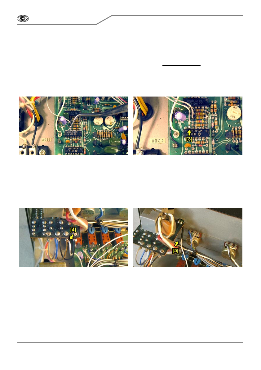
d) Cut off lead Nr. 6 of integrated circuit IC109 as nearly as poss ible at printed circuit board ( pic .
2.5.5). Align freed lead wi th a help of tweezer s (pi c. 2.5.6). Be very careful, so that no other
component and copper layer on the board are damaged!
e) S older wire Nr. 3 ”S/S -S ET“ of flat cable to fr eed lead Nr. 6 of integrated ci rc uit IC 109 ([3] on
pic. 2.5.7).
Pic. 2.5.6 Pic. 2.5.7
f) Solder wire Nr. 4 “LED - R“ to s oldering pad Nr . 3 on O P- 100A board on ins trument’s front panel
([4] on pic. 2.5.8).
g) Place heat-shrink insulation tube φ 2 mm (from the interfac e ac cess ory) on wir e Nr. 5 “LED -G“
and solder it to lead “G” (unconnected by that ti me) of newly installed bi-color LED. Isolate the
connection with the i ns ulation tube and heat it (wi th a hot-flue pistol for example) until i t shrinks tightly
to the wire and LED ’s lead ([5] on pic. 2.5.9).
Pic. 2.5.8 Pic. 2.5.9
h) Solder wi re Nr. 6 “LED -IN“ to lead Nr. 6 of IC 115 on CP U board ([6] on pi c. 2.5.1).
i) S older wire Nr. 7 “S /S-RUN“ to lead Nr. 1 of IC 109 on C PU board ([7] on pic . 2.5.1).
j) Solder wi res Nr. 8 and 9 “+5V“ to w ire-wrapping pi n Nr . 25 ( +5V) on C PU board ([8,9] on pic .
2.5.1).
k ) Solder wir es Nr. 10 and 11 “G ND “ to wire-wr appi ng pi n N r. 26 (GND) on C PU board ([10,11] on
pic. 2.5.1).
l) Solder wire Nr. 12 “+15V“ to wire-wrappi ng pi n N r. 28 (+15V) on CPU board ([12] on pic. 2.5.1).
m) Unsolder whi te wir e “In” from Jack board OP-104A (pic . 2.5.10) . If your instrument has tw o
boards wirh Jack connectors (label OP104 and OP-129), unsolder wi re leading to pad “I“ on smaller
boar d OP-129 (pic. 2.5.11).

CRX8-M
MIDI Interface for Roland CR-68 / CR-78
Model 8-449 ver. 1.0
Copyright © 2013 CHD Elektroservis . All rights reserved.
No part of this publicat ion may be reproduced in any form wit hout t he written permission of CHD Elektroservis.
1
4
P ic. 2.5.10 Pic. 2.5.11
n) S older wire Nr . 13 “C KL-OUT” of flat cable to freed s oldering pad “In“ on OP-104A board or to
pad “I“ on OP -129 board respectively ([13] on pic . 2.5.12).
o) Place heat-shrink insulation tube φ 2 mm (from the interfac e acc es sory) on freed whi te wire
and solder it to wire Nr. 14 “CLK-IN“ of flat cable. Isolate the connec tion wi th the i nsulati on tube and
heat i t (with a hot-flue pi stol for example) until it shrinks tightly to the wires ([14] on pic. 2.5.12).
Obr. 2.5.12 Obr. 2.5.13
p) Get wir e Nr. 15 “A C C ENT” of flat c able through hole i n ins tr ument’s chassis to area of sound
generators board ([15] on pic. 2.5.13). The wire will be connected to lead of res istor R660 on sound
gener ators boar d – see next c hapter.
q) Align wires of control signals flat cable and audio-cable near by origi nal i ns trument’s cabling
and fi x them wi th a help of plas tic s tri pes from the interface accessory (pi c. 2.5.14).
Pic. 2.5.14
CRX8-M
MIDI Interface for Roland CR-68 / CR-78
Model 8-449 ver. 1.0
Copyright © 2013 CHD Elektroservis . All rights reserved.
No part of this publicat ion may be reproduced in any form wit hout t he written permission of CHD Elektroservis.
1
5
2.6. FLAT CABLE OF TRIGGER SIGNALS INSTALLATION
Use remaining flat 16-wire cable from the interface acc ess ory as cable of tri gger si gnals.
Pic. 2.6.1
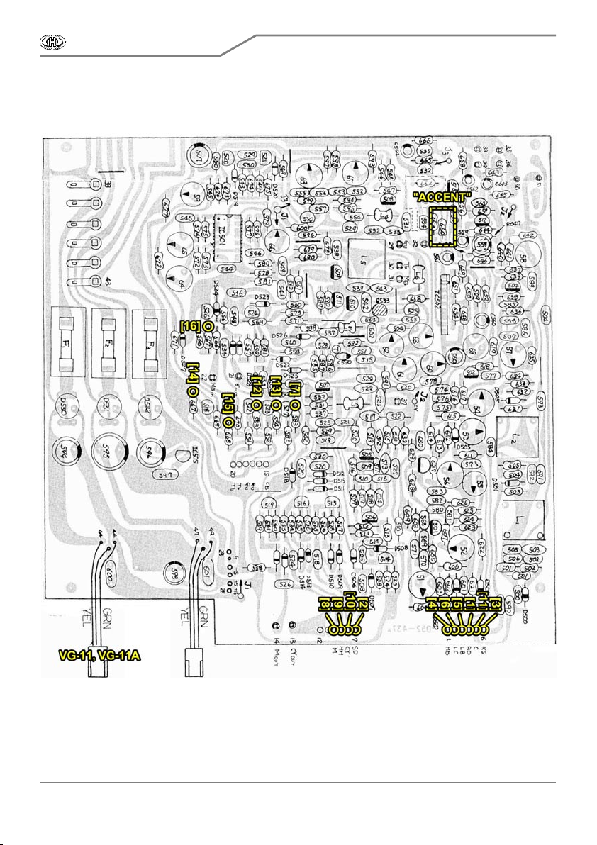
All wires of the cable will be connected to sound generators boar d fr om solder ing si de. The board
is plac ed in bottom area of the instr ument’ s chass is. Ther e are two versions of the board - with label
VG-11 (instruments with serial number up to 780699) and VG-11A (instruments with serial number
from 780700) . B oth versions are different only i n details i rrelevant for trigger s ignals cable ins tallation
so all installati on proc edur es of the c able are the same for both versions.
CRX8-M
MIDI Interface for Roland CR-68 / CR-78
Model 8-449 ver. 1.0
Copyright © 2013 CHD Elektroservis . All rights reserved.
No part of this publicat ion may be reproduced in any form wit hout t he written permission of CHD Elektroservis.
1
6
By the same way as with control signals cable, split up free end of trigger signals cable (by
ripping or cutting) to individual wires (pic. 2.6.2) and adapt their lengths as nec es sary during the c able
installation. S tripe ends of wi res i n length about 2 mm and tin them.
P artic ular w ires of trigger si gnals cable will be connec ted in ac cordance with table 2 and pic .
2.6.1. Wi re Nr. 1 is s igned with red c olor.
Table 2 – Wires of flat cable of sound generators connection
Wire Signal Point for connection Remarks
1 B as s D rum Pin Nr . 4 of flat connec tor “1~6“ C olor ed wi re
2 S nare D rum Pin Nr. of flat c onnector “7~12“
3 Rim Shot Pin Nr. 6 of flat connector “1~6“
4 High Bonga Pin Nr. 1 of flat connector “1~6“
5 Low Bonga Pin Nr. 3 of flat connector “1~6“
6 Low Conga Pin Nr. 2 of flat connec tor “ 1~6“
7 C ow Bell Upper lead of R583 resis tor (collec tor of Q 527)
8 Maracas Pin Nr. 10 of flat connector “7~12“
9 High Hat Pin Nr. 9 of flat connector “7~12“
10 C ymbal Pin Nr. 8 of flat connector “7~12“
11 C laves Pin Nr. 5 of flat connector “1~6“
12 Tambourine L Upper lead of R553 resis tor (collec tor of Q 522)
13 Tambourine H Upper lead of R554 resis tor (collec tor of Q 523)
14 G ui ro P Upper lead of R667 resis tor (base of Q518)
15 G ui ro T Upper lead of R668 resis tor (base of Q519)
16 Metallic Beat Upper lead of R567 resis tor (base of Q526)
a) Get free end of tr igger si gnals flat c able through hole i n i ns trument’s c hass is to area of sound
gener ators boar d (pi c. 2.6.3) and flip over the i ns trument upsi de down.
Pic. 2.6.2 Pic. 2.6.3
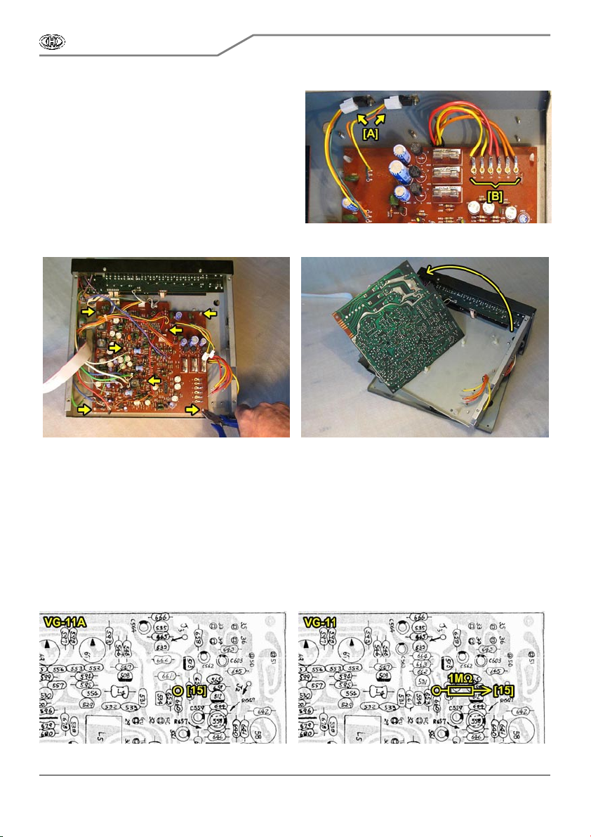
b) Wi res of the cable will be soldered to sound gener ator s boar d from soldering si de so it is
necessary to unfix the board and flip it over. Disconnect the connectors of voltage stabi lizers ([A] on
pic . 2.6.4) and unsolder leads of mains tr ansformer fr om the board ([B] on pic. 2.6.4). Make a note
about pos itions of the connec tors and the trans former leads s o that they wi ll not be exchanged or
flipped during return ass embly!
CRX8-M
MIDI Interface for Roland CR-68 / CR-78
Model 8-449 ver. 1.0
Copyright © 2013 CHD Elektroservis . All rights reserved.
No part of this publicat ion may be reproduced in any form wit hout t he written permission of CHD Elektroservis.
1
7
Pic. 2.6.4
c ) Remove sound generator s board from
plas tic dis tance spac ers – swat detents of all
spacers stepwise (7x) with a help of flat pliers for
example and lift the board simultaneously using
soft tense (pic. 2.6.5).
d) After total release of sound generators
boar d, fold up the boar d carefully. Take c ar e of
cables leading to the board so that they are not
damaged or interrupted!
Pic. 2.6.5 Pic. 2.6.6
e) C onnect wire Nr. 15 “ACC ENT“ of control signals cable – see i tem q) of previous chapter. The
wire will be connected to lead of res is tor R660 on sound generators board (“AC CE NT“ on pic. 2.6.1)
from soldering side. Method of connec tion of thi s wire depends on vers ion of s ound gener ator s
boar d. On VG-11A boar d, wire Nr . 15 “AC C ENT” i s soldered direc tly to upper lead of res istor R 660
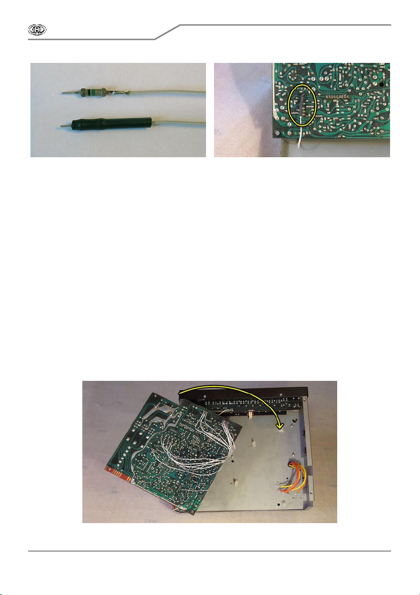
(pic. 2.6.7). On V G- 11 board, it is neces sary to ins ert seri al resistor 1MΩ from the interface accessory
(pic. 2.6.8): S older one of the res istor leads to wire Nr. 15. Place heat-shrink insulation tube φ 4 mm
(from the i nterfac e acc es sory) on the res is tor and heat the i ns ulation tube (wi th a hot-flue pi stol for
example) unti l it shri nk s tightly to the res is tor (pic. 2.6.9). Solder the other lead of 1MΩ resistor to
upper lead of resi stor R660 on sound generators board - pi c. 2.6.8 and 2.6.10.
P ic. 2.6.7 Pic. 2.6.8
CRX8-M
MIDI Interface for Roland CR-68 / CR-78
Model 8-449 ver. 1.0
Copyright © 2013 CHD Elektroservis . All rights reserved.
No part of this publicat ion may be reproduced in any form wit hout t he written permission of CHD Elektroservis.
1
8
P ic. 2.6.9 Pic. 2.6.10
f) Now, connec t wir es of tri gger s ignals cable to s ound gener ators board. Solder wire Nr. 1 “B as s
Dr um“(termi nal, si gned in red) to pin “4-B D“ of c onnec tor “1~6“ ([1] on pic. 2.6.1).
g) Solder wi re Nr. 2 “ Snar e D rum“ to pin “7-SD “ of connector “ 7~12“ ([2] on pic . 2.6.1).
h) Solder wi re Nr. 3 “Rim Shot“ to pin “6-RS“ of connector “1~6“ ([3] on pic. 2.6.1).
i) S older wire Nr. 4 “High Bonga“ to pin “1-HB“ of connector “1~6“ ([4] on pic. 2.6.1).
j) Solder wire Nr. 5 “Low B onga“ to pin “3-LB“ of c onnector “1~6“ ([5] on pic. 2.6.1).
k ) Solder wi re Nr. 6 “Low C onga“ to pin “2-LC “ of connector “ 1~6“ ([6] on pi c. 2.6.1).
l) Solder wire Nr. 7 “C ow Bell“ to upper lead of r es istor R583 ([7] on pi c. 2.6.1).
m) Solder wire Nr. 8 “Marac as “ to pin “10-M“ of connector “7~12“ ([8] on pic. 2.6.1).
n) Solder wi re Nr. 9 “High Hat“ to pin “9-HH“ of connector “7~12“ ([9] on pic. 2.6.1).
o) Solder wi re Nr. 10 “C ymbal“ to pin “8-C Y“ of connector “7~12“ ([10] on pic. 2.6.1).
p) Solder wi re Nr. 11 “C laves“ to pi n “5-C “ of connector “1~6“ ([11] on pic . 2.6.1).
q) Solder wi re Nr. 12 “ Tambourine L“ to upper lead of resi stor R553 ([12] on pi c. 2.6.1).
r) Solder wi re Nr. 13 “Tambourine H“ to upper lead of resi stor R554 ([13] on pi c. 2.6.1).
s) Solder wi re Nr. 14 “Gui ro P“ to upper lead of resistor R667 ([14] on pic . 2.6.1).
t) S older wire Nr. 15 “Guiro T“ to upper lead of resistor R668 ([15] on pic . 2.6.1).
u) Solder wire Nr. 16 “Metallic Beat“ to upper lead of resistor R567 ([16] on pic . 2.6.1).
v) After all wires are soldered, fold sound generators board to ori ginal posi tion (pi c. 2.6.11) and
get it bac k onto plas tic distance spac ers in instrument’s chas sis . P lug back connectors of voltage
stabilizers and solder back leads of mains transformer. Be sure that the c onnectors and transformer
leads are not exchanged or flipped (also see pic . 2.6.4)!
Pic. 2.6.11

CRX8-M
MIDI Interface for Roland CR-68 / CR-78
Model 8-449 ver. 1.0
Copyright © 2013 CHD Elektroservis . All rights reserved.
No part of this publicat ion may be reproduced in any form wit hout t he written permission of CHD Elektroservis.
1
9
2.7. FIN IS HIN G OF IN STALLATION
a) Put rear instrument’s panel back to chassis and fix it with four origi nal screws (pic. 2.7.1).
b) C onnect back mains cable (pic. 2.7.2). This is reverse procedure as in chapter 2.2 item c) – get
the cable through sleeve on the panel, fix it by catch clamp [A], solder the cable wires to terminal plate
[B] and s crew earth solder lug to instrument’s chass is [C].
P ic. 2.7.1 Pic. 2.7.2
c ) P lug connector of newly ins talled flat c able of control s ignals to the i nterfac e boar d ([A] on pic .
2.7.3).
d) Plug connector of newly installed flat cable of trigger signals (leadi ng fr om sound generators
board V G-11x) to the interface board ([B] on pic . 2.7.3).
e) Plug c onnector of newly i ns talled audi o- cable (leading from OP -103A boar d) to the i nterfac e
board ([C ] on pic . 2.7.3).
f) Plug jumper on the interface board to position “78“ (pic. 2.7.4).
P ic. 2.7.3 Pic. 2.7.4
Pic. 2.7.5
g) Ins er t J ac k connec tor s boar s (OP -104A,
or both boards OP104 and OP129 respectively) to
origi nal pos iti on in instrument’ s rear panel. Fix the
boar d with nuts of J ac k connec tors. D on’t forget to
insert the insulation washers (pic. 2.7.5)!
h) Plug flat connector of bunched cables
leading from the Jack board back to CPU board of
the instrument. Orientati on of the connector i s
unambiguous ly given by the connector lock and it
can’t be plugged on the contrary (also see pic.
2.2.1.1).
CRX8-M
MIDI Interface for Roland CR-68 / CR-78
Model 8-449 ver. 1.0
Copyright © 2013 CHD Elektroservis . All rights reserved.
No part of this publicat ion may be reproduced in any form wit hout t he written permission of CHD Elektroservis.
2
0
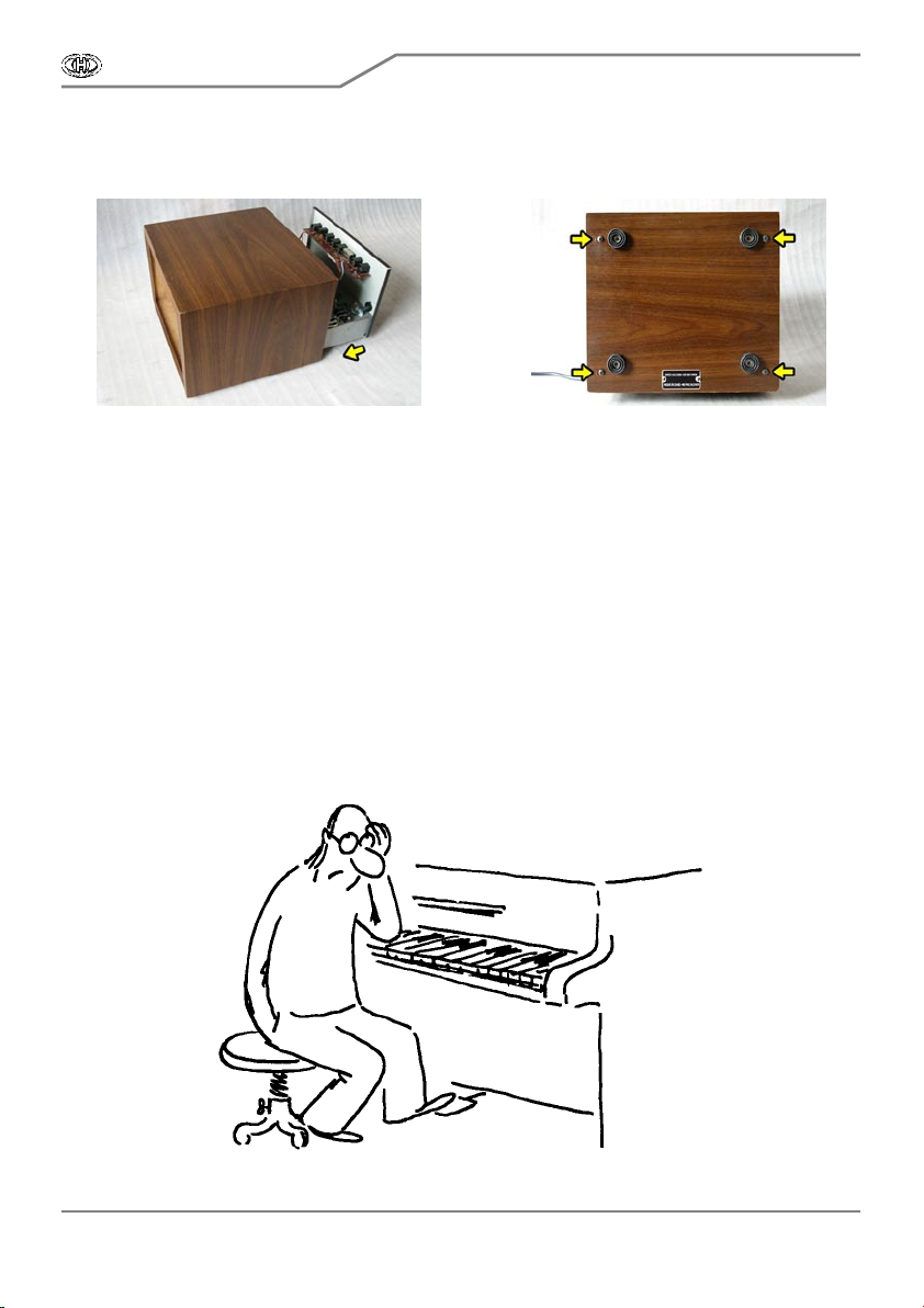
i) Intromit c hassis of the instrument back to cover (pic. 2.7.6).
j) Fix the cover from bottom s ide wi th a help of four original screws (pic . 2.7.7).
P ic. 2.7.6 Pic. 2.7.7
Installation of the MIDI interface kit is now finished and the instrument is prepared for
communication via MIDI bus.
Please read carefully user manual of the interface before usage of modifi ed instrument.
3. TIP TO CR-78 INSTRUMENT MODIFICATION
On some ins truments , sound generator Tambourine Shor t is sounding too long so it is practically
impos si ble to dis tinguish it from s ound of Tambour ine Long generator. Shortening of period when
Tambourine Short generator i s s ounding c an be done by decreasi ng of value of R555 resistor (270
kΩ originally) on boar d VG -11 or VG-11A res pecti vely. C onnecti on of 75 kΩ resi stor in parallel manner
to R555 get ri ght.
* * * * *
Other manuals for CRX8-M
1
Table of contents


