CHD Elektroservis Savvy User manual
Tone Parameters
Tone ParametersTone Parameters
Tone Parameters
Editor & Controller
Editor & ControllerEditor & Controller
Editor & Controller
Version 1.0
Version 1.0Version 1.0
Version 1.0
Service Manual
Service ManualService Manual
Service Manual
© 2018 CHD Elektroservis
© 2018 CHD Elektroservis© 2018 CHD Elektroservis
© 2018 CHD Elektroservis

Tone P
Tone PTone P
Tone Parameters Editor
arameters Editor arameters Editor
arameters Editor &
&&
& Controller
Controller Controller
Controller
Service Manual
Service ManualService Manual
Service Manual
Model TPE
Model TPEModel TPE
Model TPE-
--
-1 / BIOS ver. 1.00
1 / BIOS ver. 1.001 / BIOS ver. 1.00
1 / BIOS ver. 1.00
Copyright © 2018 CHD Elektroservis. All rights reserved.
No part of this publication may be reproduced in any form without the written permission of CHD Elektroservis.
2
2
2
2
1
11
1
PRINCIPLE OF THE SAVVY FUNCTION
PRINCIPLE OF THE SAVVY FUNCTIONPRINCIPLE OF THE SAVVY FUNCTION
PRINCIPLE OF THE SAVVY FUNCTION
Internal structure of the SAVVY editor memory areas and data processing shows Figure 1:
Figure 1
Figure 1 Figure 1
Figure 1 –
––
– Internal structure of
Internal structure of Internal structure of
Internal structure of the SAVVY editor
the SAVVY editorthe SAVVY editor
the SAVVY editor
Since the editor can control more instruments (but not
notnot
not more instruments simultaneously!
simultaneously!simultaneously!
simultaneously!) with different
communication protocols, it has part of internal memory reserved for information about chosen instrument -
Operational System Memor
Operational System MemorOperational System Memor
Operational System Memory
yy
y. Operational system is downloadable by user via MIDI SyEx
①
. CPU of SAVVY then
works in dependence on loaded operational system
②
.
For parameters which control basic functions of the editor, part of internal memory named System Parameters
System Parameters System Parameters
System Parameters
Memory
MemoryMemory
Memory is reserved. This memory bank can be loaded with user data or stored data can be read via MIDI SyEx
③
. CPU of the editor then reads stored parameters
④
and works in accordance with them. Note that the
general parameters are different for each of instruments!
For assignment of CCs numbers used actually for the instrument control, part of internal memory named
Instrument Parameters Memory
Instrument Parameters MemoryInstrument Parameters Memory
Instrument Parameters Memory is reserved. Again, this memory bank can be loaded with user data or stored
data can be read via MIDI SyEx
⑤
. CPU of the editor then works in accordance with assigned CCs
⑥
. Note that
the instrument parameters are different for each of instruments!
The editor has its own memory (Tone Data Bank
Tone Data BankTone Data Bank
Tone Data Bank) of individual tone parameters for controlled instrument. This
bank (stored tones) is independent on the controlled instrument memories. Each part of the memory bank
(tone) can be loaded with own user data or content of a part of memory bank (tone) can be transmitted from
the editor the (the tone data can be archived) as Bulk Dump MIDI SysEx
⑦
.
Tone P
Tone PTone P
Tone Parameters Editor
arameters Editor arameters Editor
arameters Editor &
&&
& Controller
Controller Controller
Controller
Service Manual
Service ManualService Manual
Service Manual
Model TPE
Model TPEModel TPE
Model TPE-
--
-1 / BIOS ver. 1.00
1 / BIOS ver. 1.001 / BIOS ver. 1.00
1 / BIOS ver. 1.00
Copyright © 2018 CHD Elektroservis. All rights reserved.
No part of this publication may be reproduced in any form without the written permission of CHD Elektroservis.
3
3
3
3
The active tone can be selected manually from the device panel anytime (by or buttons) or via Program
Change / Bank Select MIDI commands in dependence on system parameters setting. When a tone is set as
active from the controller, data from corresponding part of tone bank are copied to tone edit buffer
⑧
and
then transferred to controlled instrument as SysEx messages
⑨
. When a tone is set as active from controlled
instrument, data from corresponding part of tone bank are copied to tone edit buffer
⑧
and they can be
simultaneously sent to the controller as stream of CCs
⑩
.
Control Changes (CCs) MIDI commands received from the controller
⑩
are divided to assigned (by an
instrument parameter) and unassigned to a tone parameter. Assigned CCs are converted to control SysEx data
and then sent to the instrument
⑨
. Unassigned CCs are only transferred through the device
⑪
. In opposite
direction, all CCs received from the controller
⑪
are only transferred through the device
⑩
.
Program Change MIDI commands received from the controller
⑫
can change actual part of tone bank
⑧
and /
or they are transferred to controlled instrument [13] in dependence on setting of system parameters. The same
goes for the opposite communication direction – Program Change commands received from controlled
instrument
⑬
can change actual tone bank
⑧
and / or they are transferred to the controller
⑫
in dependence
on setting of system parameters.
SysEx messages incoming from the controlled instrument
⑨
can be converted and sent to the controller as CCs
⑩
in dependence on setting of system parameters.
Direct Control MIDI SysEx commands (i.e. Bulk Dump Request and Initialize)
⑭
are processed by CPU of the
SAVVY immediately after their receiving. Please see description of SysEx communication.
All other MIDI commands (i.e. unused channel commands, all common system commands and unacceptable
SysEx) are only transferred through the editor without any change
⑮
(in both communication directions).
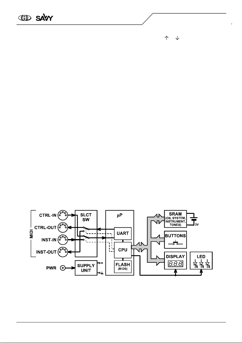
Figure 2
Figure 2 Figure 2
Figure 2 –
––
– Block schematics diagram
Block schematics diagram Block schematics diagram
Block schematics diagram

Tone P
Tone PTone P
Tone Parameters Editor
arameters Editor arameters Editor
arameters Editor &
&&
& Controller
Controller Controller
Controller
Service Manual
Service ManualService Manual
Service Manual
Model TPE
Model TPEModel TPE
Model TPE-
--
-1 / BIOS ver. 1.00
1 / BIOS ver. 1.001 / BIOS ver. 1.00
1 / BIOS ver. 1.00
Copyright © 2018 CHD Elektroservis. All rights reserved.
No part of this publication may be reproduced in any form without the written permission of CHD Elektroservis.
4
44
4
2
22
2
B
BB
BACKUP BATTERY REPLACEMENT
ACKUP BATTERY REPLACEMENTACKUP BATTERY REPLACEMENT
ACKUP BATTERY REPLACEMENT
The SAVVY device’s internal memory is powered from battery cell when the device is disconnected from power
supply adapter. The battery has a life of about five years. The battery should be replaced after this time or
when its voltage falls under 2,7 V . For replacement, use standard lithium battery cell CR2032
CR2032CR2032
CR2032 type (lithium).
The battery is placed on PCB inside the device. So it necessary to open the device.
2
22
2.1. Opening the device
.1. Opening the device.1. Opening the device
.1. Opening the device
Turn the device upside down. Unscrew four self-tapping screws on the bottom cover (Fig. 3) and remove the
bottom cover.
Figure 3.
Figure 3. Figure 3.
Figure 3. –
––
– Bottom cover removing
Bottom cover removing Bottom cover removing
Bottom cover removing
2
22
2.2. Battery cell replacement
.2. Battery cell replacement.2. Battery cell replacement
.2. Battery cell replacement
Remove old battery from holder on PCB (Fig. 4) and replace it with new one. Use CR2032
CR2032CR2032
CR2032 type lithium battery
cell only!
Figure 4.
Figure 4. Figure 4.
Figure 4. –
––
– Battery replacement
Battery replacement Battery replacement
Battery replacement
2
22
2.3. Refitting the device
.3. Refitting the device.3. Refitting the device
.3. Refitting the device
Put the bottom cover back on the device and fix it with four original self-tapping screws.
Notice:
Notice:Notice:
Notice: The old battery should not be disposed as general household waste! You should look for
appropriate recycling facilities and systems for the disposal of this product.

Tone P
Tone PTone P
Tone Parameters Editor
arameters Editor arameters Editor
arameters Editor &
&&
& Controller
Controller Controller
Controller
Service Manual
Service ManualService Manual
Service Manual
Model TPE
Model TPEModel TPE
Model TPE-
--
-1 / BIOS ver. 1.00
1 / BIOS ver. 1.001 / BIOS ver. 1.00
1 / BIOS ver. 1.00
Copyright © 2018 CHD Elektroservis. All rights reserved.
No part of this publication may be reproduced in any form without the written permission of CHD Elektroservis.
5
5
5
5
3
33
3
HARDWARE TESTS
HARDWARE TESTSHARDWARE TESTS
HARDWARE TESTS
The SAVVY device’s basic software (BIOS) contains routines for checking of functionality of its own hardware.
Testing procedures can be executed if display of the device doesn’t show correctly for example or if the device
does not work properly with MIDI system, etc.;
3
33
3.1. Enter to testing mode
.1. Enter to testing mode.1. Enter to testing mode
.1. Enter to testing mode
For enter into the testing mode, press and buttons
and hold both them pressed
①
. Then turn the device on
– connect power supply adapter to the device
②
. After
that, all decimal points of display and all LEDs ( ,
and ) light
③
. Now, and
buttons
①
can be released – the device is incoming to
testing mode.
3
33
3.2. Test of display and LEDs
.2. Test of display and LEDs.2. Test of display and LEDs
.2. Test of display and LEDs
Test of the display and LEDs is launched automatically after entering into testing mode. All LEDs and segments
of display light in this cycle:
1. CTRL
CTRLCTRL
CTRL→INST
→INST→INST
→INST LED and sequentially all segments (see Fig. 5.) on left position of the display
2. INST
INSTINST
INST→CTRL
→CTRL→CTRL
→CTRL LED and sequentially all segments (see Fig. 5.) on middle position of the display
3. EDITED
EDITEDEDITED
EDITED LED and sequentially all segments (see Fig. 5.) on right position of the display
Figure 5.
Figure 5. Figure 5.
Figure 5. –
––
– Sequence of d
Sequence of d Sequence of d
Sequence of display segments lighting
isplay segments lightingisplay segments lighting
isplay segments lighting
Continue to next test occurs after any of buttons is pressed.
3
33
3.3. Test of buttons
.3. Test of buttons.3. Test of buttons
.3. Test of buttons
The display shows “b.
b. b.
b. --
----
--” symbols where “b.
b.b.
b.” means “buttons”. Now you have to press sequentially all buttons.
It doesn’t matter in what order the buttons are pressed.
Pressing of each of buttons is indicated on the display – by corresponding lighting segment (see table 1). The
segment remains light after the button is depressed.
Table 1
Table 1 Table 1
Table 1 –
––
– INDICATION OF PRESSED BUTTONS
INDICATION OF PRESSED BUTTONS INDICATION OF PRESSED BUTTONS
INDICATION OF PRESSED BUTTONS
Button
ButtonButton
Button
Display
DisplayDisplay
Display Button
ButtonButton
Button
Disp
DispDisp
Display
laylay
lay Button
ButtonButton
Button
Display
DisplayDisplay
Display
,
,
After all buttons are pressed :
After all buttons are pressed, the display shows “b. ok
b. okb. ok
b. ok” symbols for approx. one second. This indicates proper
function of all buttons. Then the device goes to next test automatically.
3
33
3.4. Test of display brightness control
.4. Test of display brightness control.4. Test of display brightness control
.4. Test of display brightness control
The display shows “d. nn
d. nnd. nn
d. nn” symbols where “d.
d.d.
d.” means “display” and “nn
nnnn
nn” is value (from 0 to 15) of actual
brightness of the display. The brightness can be changed by and buttons. button increments the
Tone P
Tone PTone P
Tone Parameters Editor
arameters Editor arameters Editor
arameters Editor &
&&
& Controller
Controller Controller
Controller
Service Manual
Service ManualService Manual
Service Manual
Model TPE
Model TPEModel TPE
Model TPE-
--
-1 / BIOS ver. 1.00
1 / BIOS ver. 1.001 / BIOS ver. 1.00
1 / BIOS ver. 1.00
Copyright © 2018 CHD Elektroservis. All rights reserved.
No part of this publication may be reproduced in any form without the written permission of CHD Elektroservis.
6
6
6
6
brightness, button decrements the brightness. Anytime the buttons are pressed, the brightness goes up or
down respectively in one step in range from 0 to 15.
For continue to next test, RESET button need to be pressed.
3
33
3.5. Test of internal RAM memory
.5. Test of internal RAM memory.5. Test of internal RAM memory
.5. Test of internal RAM memory
The test runs automatically. The display shows “r. nn
r. nnr. nn
r. nn” symbols. where “r.
r.r.
r.” means “RAM” and “nn
nnnn
nn” is number of
block of RAM cells under testing procedure. During the test, block numbers 1 to 32 are displayed sequentially.
Each of these 32 blocks of RAM cells has size 4096 byte. After whole area of RAM cells are checked successfully,
the display shows “r.ok
r.okr.ok
r.ok” symbols for approx. one second and then the device continues to next test
automatically.
If any defective memory cell is detected during the RAM test, display shows “r. E. n
r. E. nr. E. n
r. E. n” symbols (RAM Error) where
“n
nn
n” is number of the error (see table 2). In this case, continue to next test occurs after button is pressed.
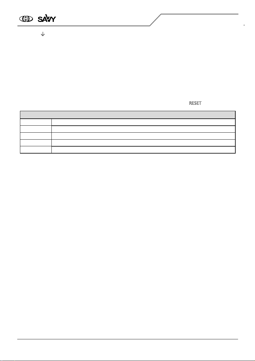
Table 2
Table 2 Table 2
Table 2 –
––
– POSSIBLE ERRORS DURING RAM TESTING PROCEDURE
POSSIBLE ERRORS DURING RAM TESTING PROCEDURE POSSIBLE ERRORS DURING RAM TESTING PROCEDURE
POSSIBLE ERRORS DURING RAM TESTING PROCEDURE
Error number
Error numberError number
Error number
Error description
Error descriptionError description
Error description
E.1, E.2 Wrong reaction to Read / Write instruction in lower part of RAM.
E.3 Content of cell in lower part of RAM can’t be refreshed.
E.4, E.5 Wrong reaction to Read / Write instruction in upper part of RAM.
E.6 Content of cell in upper part of RAM can’t be refreshed.
3
33
3.6. Test of MIDI inputs and outputs
.6. Test of MIDI inputs and outputs.6. Test of MIDI inputs and outputs
.6. Test of MIDI inputs and outputs
Standard MIDI cable (with DIN 41524 connectors on both ends) is necessary for execution of this testing
routine. Individual MIDI inputs and outputs of the device will be interconnected with help of this cable.
The test is indicated by symbol “M.
M.M.
M.” on the display – it means “MIDI”.
Until no MIDI input is connected with no MIDI output, symbols “--
----
--“ is shown on the display. Connection of
arbitrary MIDI input with arbitrary MIDI output is indicated by symbols of two characters. First of them
indicates used MIDI output (“i
iii” = INSTRUMENT-OUT, “c
cc
c” = CONTROLLER-OUT) and the second indicates used
MIDI input (“i
iii” = INSTRUMENT-IN, “c
cc
c” = CONTROLLER-IN).
If symbol “--
----
--“ is still displayed or if symbol “-
--
-?
??
?” is displayed after a MIDI input is interconnected with a MIDI
output, used MIDI input or MIDI output respectively is not working correctly.
For continue to next test, RESET button need to be pressed.
3
33
3.7. Displaying of basic software
.7. Displaying of basic software .7. Displaying of basic software
.7. Displaying of basic software version
versionversion
version
The test is indicated by symbol “v.
v.v.
v.” on the display – it means “version”.
Then moving text “bioS vEr. n.nn
bioS vEr. n.nnbioS vEr. n.nn
bioS vEr. n.nn” is shown on the display. The “n.nn
n.nnn.nn
n.nn” in the text is number of version of basic
software (BIOS) installed in the device (e.g. 1.00).
For continue, RESET button need to be pressed.
3
33
3.8. End of tests
.8. End of tests .8. End of tests
.8. End of tests
After all testing procedures are finished, display shows “End
EndEnd
End” symbols and the device stops all operations. Now,
you can disconnect power supply adapter from the device.
If no error occurs during testing procedures, the device is fully functional and it should to work with MIDI
system correctly.
If any hardware malfunction was detected during testing procedures, the device must be repaired in specialized
workshop.
Tone P
Tone PTone P
Tone Parameters Editor
arameters Editor arameters Editor
arameters Editor &
&&
& Controller
Controller Controller
Controller
Service Manual
Service ManualService Manual
Service Manual
Model TPE
Model TPEModel TPE
Model TPE-
--
-1 / BIOS ver. 1.00
1 / BIOS ver. 1.001 / BIOS ver. 1.00
1 / BIOS ver. 1.00
Copyright © 2018 CHD Elektroservis. All rights reserved.
No part of this publication may be reproduced in any form without the written permission of CHD Elektroservis.
7
7
7
7
Tone Parameters Editor & Controller
Model TPE-1 Nr. 8-361 / Bios v. 1.00
Document: 8361100_service
Manufacturer:
CHD Elektroservis, Czech Republic
www.chd-el.cz info@chd-el.cz

Table of contents
Other CHD Elektroservis Recording Equipment manuals


