ABB 83327-500 User manual

VER:1.0 │ │12.10.2015
ABB-Welcome
Pos: 2/Di nA4 - Anleitung enO nline/Inhalt/KNX/D oorEntry/832 20-AP-xxx/Tit elblatt - 83220-AP-xxx - ABB @ 19\mod_1 323249806476_15. docx@ 11 1084@ @ 1
83327-500
Camera interface
=== Ende der List ef ür Textmar keCo ver ===

ABB-Welcome
|
—2 —
Pos: 4 /Busch-Ja eger( Neustruktur)/M odul-Stru ktur/Online-Dokum entation/Inhalts verzeichnis (--> Für alleD okument e<--) /Inhaltsverzeichnis @ 19\ mod_132064904438 6_15.docx @ 109653 @ @ 1
1Safety............................................................................................................3
2Intended use..................................................................................................3
3Environment ..................................................................................................3
3.1 ABB devices.................................................................................3
4Operation.......................................................................................................5
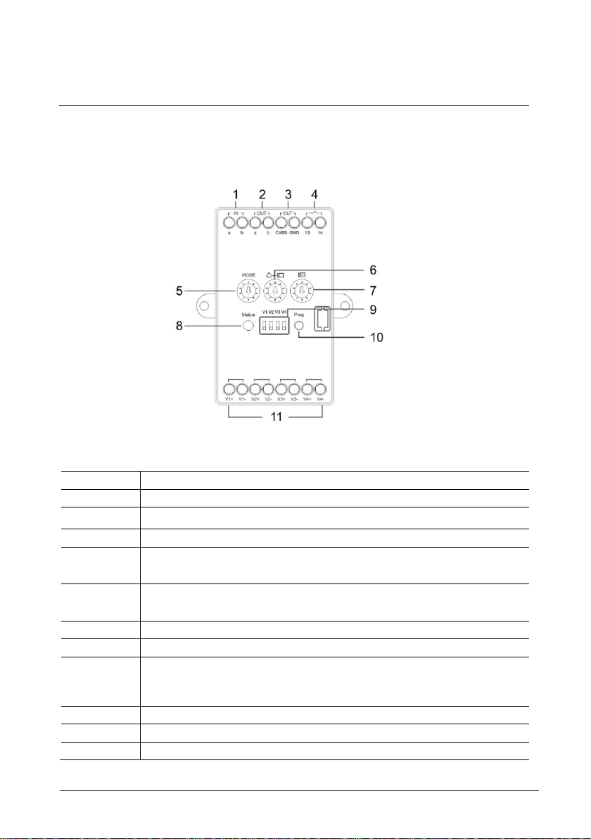
4.1 Control elements ..........................................................................5
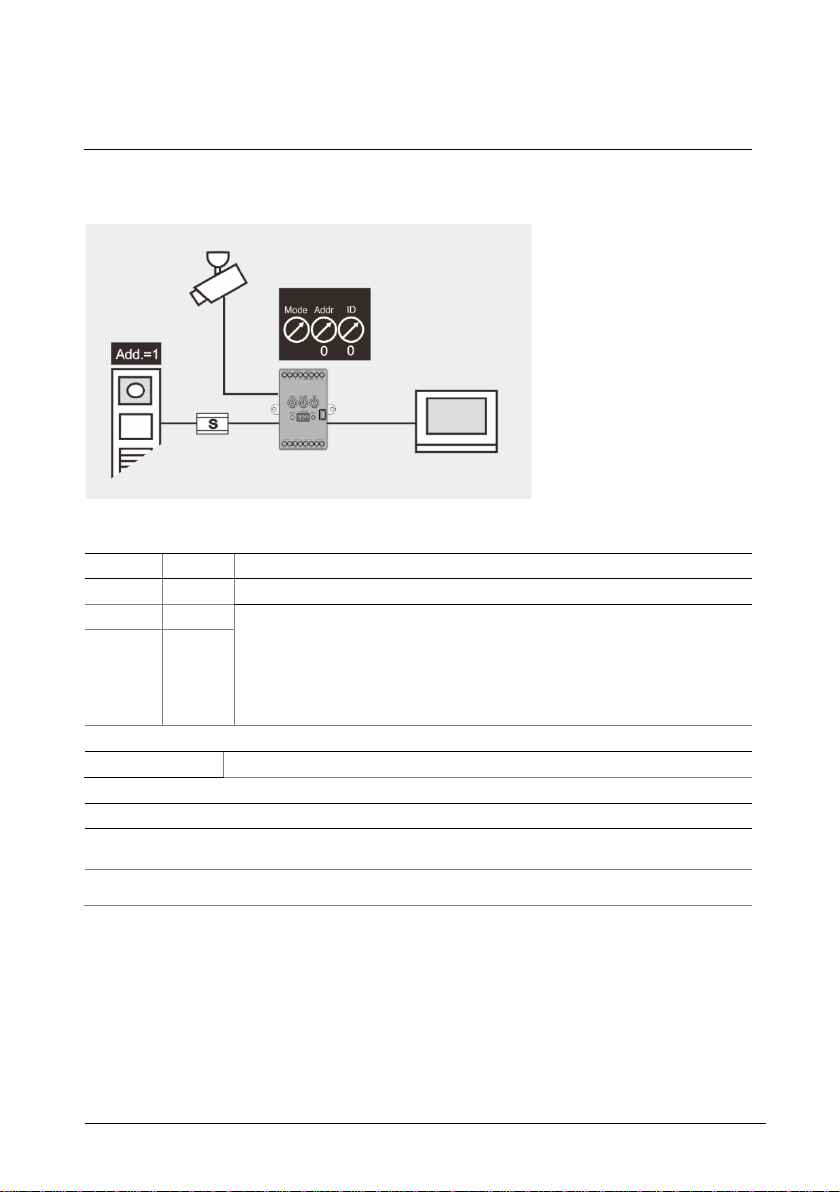
4.2 Operating modes..........................................................................6
4.2.1 Mode=1, works as an independent outdoor station......................6
4.2.2 Mode=2, works associated with outdoor station...........................7
4.2.3 Mode=3, works associated with guard unit...................................8
4.2.4 Mode=4, programming mode........................................................9
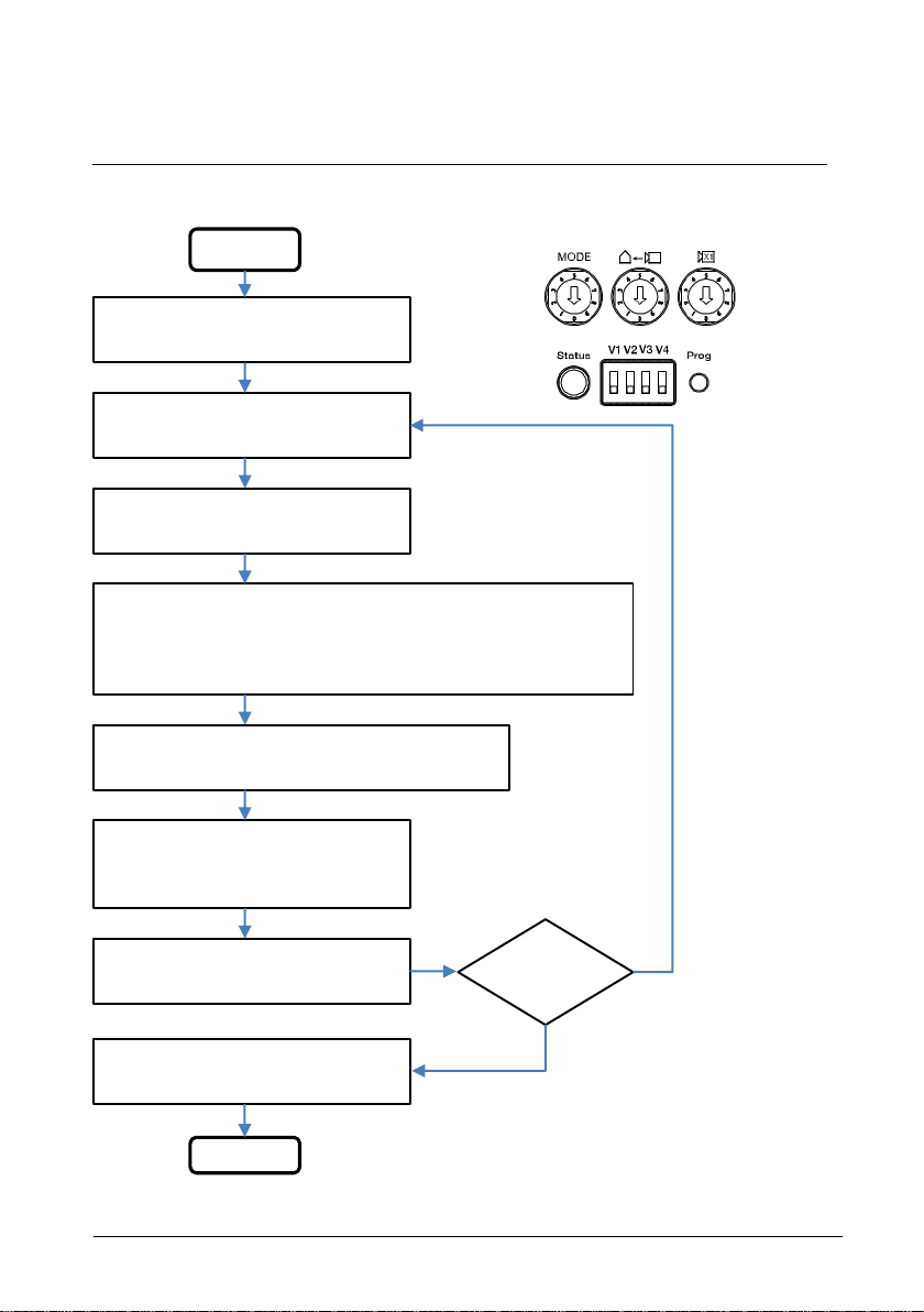
4.3 Programming mode....................................................................10
4.4 With and without permanent power supply.................................11
4.5 Video signal from third party DVR ..............................................12
4.6 Video signal to be stored to third party DVR...............................13
5Technical data.............................................................................................14
5.1 Overview table............................................................................14
5.2 Device connection diagram ........................................................14
6Mounting/Installation....................................................................................15
6.1 Requirements for the electrician.................................................15
6.2 General installation instructions..................................................16
6.3 Mounting.....................................................................................17
6.3.1 Surface-mounted installation......................................................17
6.3.2 Flush-mounted installation..........................................................17
6.3.3 DIN installation ...........................................................................17
=== Ende der Liste fürT extmarke TOC ===

ABB-Welcome
Safety
|
—3 —
Pos: 6 /Busch-Ja eger( Neustruktur)/M odul-Stru ktur/Online-Dokumen tation/Überschrifte n( --> Für alle Dokum ente <--)/1. Ebene/S - T/Sicherheit @ 18\mod _1302612791790_1 5.docx @ 103357@ 1 @ 1
1 Safety
Pos: 7/ Busch-Jaeger (Neus truktur)/Modul-Str uktur/Online-Dokum entation/Sicherheit (--> Für alle Doku mente< --)/Warnhin weise/Sicherheit - 230 V @ 18\mod_1302606 816750_15.docx @ 103308 @ @ 1
Warning
Electric voltage!
Risk of death and fire due to electrical voltage of 100-240 V.
–Work on the 100-240 V supply system may only be performed by
authorized electricians!
–Disconnect the mains power supply prior to installation and/or
disassembly!
Pos: 8 /Busch-Ja eger( Neustruktur)/M odul-Stru ktur/Online-Dokum entation/Überschrift en (--> Füralle Do kumente <--)/1. Ebene/A - F/Besti mmungsgemäßer Gebrauch @ 18\mod_ 1302763321316_1 5.docx@ 1 03483 @ 1 @ 1
2 Intended use
Pos: 9/Di nA4 - Anleitung enO nline/Inhalt/KNX/D oorEntry/832 20-AP-xxx/B estimmungsg emaesser Gebra uch- 8 3220-AP-xxx-500 @ 20\mod_1 324561168699_15.d ocx@ 1 12728 @ @ 1
This device integrates analog camera into the ABB-Welcome door entry system. Up to 4
analog cameras can be connected to 1 camera interface. Each external camera is
powered independently.
Pos: 10 /Busch-Jaeg er( Neustruktur)/Mo dul-Struktur/Onlin e-Dokumentation/Üb erschriften (--> Für alleD okument e<--) /1. Ebene/U -Z/U mwelt @ 18\mod_1302 614158967_15.docx @ 10 3383@ 1 @ 1
3 Environment
Pos: 11 /Busc h-Jaeg er (Neustr uktur)/Modul- Struktur/O nline-Doku mentation/U mwelt (--> Für alleD okum ente<--)/Hi nweise/Hin weis- U mwelt- Hinweis Ele ktrogeräte@ 18\m od_130276397343 4_15.docx @ 103500 @ @1
Consider the protection of the environment!
Used electric and electronic devices must not be disposed of with
household waste.
–The device contains valuable raw materials that can be recycled.
Therefore, dispose of the device at the appropriate recycling
facility.
Pos: 12 /DinA4 - Anleitungen Online/Ue berschriften/2./ABB G eraete@ 1 9\mod_13231628 43832_15.docx @ 110875 @ 2 @ 1
3.1 ABB devices
Pos: 13 /Busc h-Jaeg er (Neustr uktur)/Modul- Struktur/O nline-Doku mentation/U mwelt (--> Für alleD okum ente<--)/Hi nweise/Hi nweis - Umwelt - ABB Elektrogeräte @ 19\mod_13231 62745839_15.doc x@ 110 867@ @ 1
All packaging materials and devices from ABB bear the markings and test seals for
proper disposal. Always dispose of the packaging material and electric devices and their
components via an authorized recycling facilities or disposal companies.

ABB-Welcome
Environment
|
—4 —
ABB products meet the legal requirements, in particular the laws governing electronic
and electrical devices and the REACH ordinance.
(EU-Directive 2002/96/EG WEEE and 2002/95/EG RoHS)
(EU-REACH ordinance and law for the implementation of the ordinance (EG)
No.1907/2006)

ABB-Welcome
Operation
|
—5 —
Pos: 18 /DinA4 - Anleitunge n Online/Ueberschrif ten/1./Bedienu ng@ 1 8\mod_13026 13924165_15.doc x@ 103 365 @ 1@ 1
4 Operation
Pos: 19 /DinA4 - Anleitunge n Online/Ueberschrif ten/2./Norm aler Betrieb @ 18\mod_ 1302768820965_ 15.docx @ 103540 @ 2 @ 1
4.1 Control elements
Pos: 20 /DinA4 - Anleitunge n Online/Ueberschrif ten/3./Bedienel emente @ 20\mod_ 132326022055 9_15.docx @ 111647 @ 3 @ 1
Pos: 21 /DinA4 - Anleitunge n Online/Inhalt/KN X/DoorEntry/83 220-AP-xxx/Bedieneleme nte- 83220-AP- xxx @ 18\mod_13032 12853605_15.doc x@ 103673 @ @ 1
Fig.
1
: Overview of control buttons
No.
Functions
1
Bus in
2
Bus out
3
CVBS out
4
Switch on camera power supply.
For details, please see Chapter 4.4 With & Without permanent power
supply
5
Working mode
There are 4 modes for the camera interface, For details, please see
Chapter 4.3 Operation mode.
6
Set the address of the associated devices.
7
Set the address of the camera interface.
8
Operating status notification LED
-Green: ready for operation
-Orange: in setting mode
-Red: fault
9
Dip switch to switch on/off the video channel.
10
Program button to enter the programming mode.
11
4 video in. (supports CVBS signal input)
Pos: 22 /Busch-J aeger (Neustru ktur)/Modul-Struktur /Online-Doku mentation/Steu ermodule - Onli ne-Dokumentation (--> F üralle Do kumente <--)/+++++ +++++++ Seitenum bruch++ +++++++ +++ @ 9\mod _1268898668 093_0.docx @ 5 2149 @ @ 1

ABB-Welcome
Operation
|
—6 —
Pos: 26 /DinA4 - Anleitunge n Online/Ueberschrif ten/2./Bediena ktionen @ 20\mod_1 323262294281_1 5.docx @ 111911 @ 2 @ 1
4.2 Operating modes
Pos: 71 /DinA4 - Anleitunge n Online/Ueberschrif ten/3./Abschlus swiderstand @ 19\ mod_132195 8079906_15.docx @ 110083 @ 3 @ 1
Pos: 72 /DinA4 - Anleitunge n Online/Inhalt/KN X/DoorEntry/Be dienung/Abschl usswiderstand setzen 8 3220-AP-xxx @ 19\m od_1310723392369 _15.docx @ 107841 @ @1
4.2.1 Mode=1, works as an independent outdoor station
Fig.
2
: Mode=1, works as an independent outdoor station
Rotary
Value
Note
Mode
1
Camera interface works as an independent camera interface.
Addr
null
——
ID
2
ID starts from 1 to 9 sequentially, and should not be the same
address of camera interface or other camera interface.
Pos: 74 /DinA4 - Anleitunge n Online/Inhalt/KN X/DoorEntry/Be dienung/Master/Sl aveS chalter setzen 83 220-AP-xxx @ 19\mod_1310723 320966_15.docx @ 107833 @ @
Dip Switch 1-4
Turn to ON when a camera is connected.
Capacity
Each camera interface supports 4 analog cameras.
A total 9 camera interfaces (mode=1) in one system.
Operation
Press to view the cameras individually during surveillance.

ABB-Welcome
Operation
|
—7 —
4.2.2 Mode=2, works associated with outdoor station
Fig.
3
: Mode=2, works associated with outdoor station
Rotary
Value
Note
Mode
2
Camera interface work associated with outdoor station.
Addr
1
Address of the associated outdoor station, from 1-9.
ID
1
ID can be set from 1-9, and should be unique.
Dip Switch 1-4
Turn to ON when a camera is connected.
Capacity
Each camera interface supports 4 analog cameras.
A total of 15 cameras can be associated with each outdoor station (including 2 built-in cameras in
outdoor station).
Operation
Press to view the cameras individually during surveillance.
Pos: 74 /DinA4 - Anleitunge n Online/Inhalt/KN X/DoorEntry/Be dienung/Master/Sl aveS chalter setzen 83 220-AP-xxx @ 19\mod_1310723 320966_15.docx @ 107833 @ @

ABB-Welcome
Operation
|
—8 —
4.2.3 Mode=3, works associated with guard unit
Fig.
4
: Mode=3, works associated with guard unit
Rotary
Value
Note
Mode
3
Camera interface work associated with guard unit.
Addr
1
Address of guard unit, from 1-9.
ID
1
ID can be set from 1-9, and should be unique.
Dip Switch 1-4
Turn to ON when a camera is connected.
Capacity
Each camera interface supports 4 analog cameras.
A total of 15 cameras can be associated with each guard unit.
Operation
During communication, image can be sent from guard unit to indoor station by pressing the
"Enable" button.
Pos: 75 /Busch-J aeger (Neustru ktur)/Modul-Struktur /Online-Doku mentation/Steu ermodule - Onli ne-Dokumentation (--> F üralle Do kumente <--)/+++++ +++++++ Seitenum bruch++ +++++++ +++ @ 9\mod _1268898668 093_0.docx @ 5 2149 @ @ 1

ABB-Welcome
Operation
|
—9 —
4.2.4 Mode=4, programming mode
Fig.
5
: mode=4, programming mode
Rotary
Value
Note
Mode
4
Camera interface works in programming mode.
Addr
null
Camera interface mode, camera interface address and associated device
address can all be programmed with software.
In mode=4, besides camera interface and guard unit, camera interface
can also be associated with video indoor station.
If camera interface is associated with video indoor station, ID should start
from 1 to 9 sequently.
For details, see Chapter 4.3 Programming mode.
ID
null
Dip Switch 1-4
Turn to ON when a camera is connected.
Capacity
Each camera interface supports 4 analog cameras. Each camera can be associated with
different devices (i.e., outdoor station, guard unit, video indoor station).
A total of 36 cameras can be associated with each video indoor station. Each camera can be
associated with 250 indoor stations.

ABB-Welcome
Operation
|
—10 —
4.3 Programming mode
start
1. Long press “
Prog” button for 3s to
enter programming mode
2. Choose cameras to set by dip switch
V1/V2/V3/V4
4. Set the working mode by R1
Mode=1, Camera interface works as an independent
outdoor station.
Mode=2, Camera interface works associated with
outdoor station.
Mode=3, Camera interface works associated with
guard unit.
Mode=4, Camera interface works associated with indoor station
3. Assign the address of the camera
interface by R3
5. Short-press "
Prog" button to save current setting
6. Set the address of the associated
device by these three rotary switches
(R1&R2&R3)
Address=R1*100+R2*10+R3
continue to
program
8. Long press “Prog” button 3s to exit
programming mode
End
7. Short-press "Prog" button to save
current setting
N
Y
R1
R2
R3

ABB-Welcome
Operation
|
—11 —
4.4 With and without permanent power supply
+
-
12V
+
-
12V
Camera with permanent power supply
Camera without permanent power supply

ABB-Welcome
Operation
|
—12 —
4.5 Video signal from third party DVR
Fig.
6
: Video signal from third party DVR
Note:
1) DVR output can be one of the inputs for camera interface in modes 1, 2, 3, and 4.
2) Each camera Interface supports 4 DVR singnals.
DVR

ABB-Welcome
Operation
|
—13 —
4.6 Video signal to be stored to third party DVR
Fig.
7
: Video signal to be stored to third party DVR
Note:
1) Camera interface sends video to video indoor station and also to DVR/TV through the
CVBS output port.
2) Each camera interface supports 1 CVBS output.
3) After connecting CVBS output to DRV/TV, there are two options for sending video to
DVR:
-Camera interface mode=2, video outdoor station calls video indoor station.
-Camera interface mode=3, "Enable" button is pressed at guard unit.
4) Camera interface doesn’t send video to DVR/TV during video Indoor station
surveillance.
Pos: 75 /Busch-J aeger (Neustru ktur)/Modul-Struktur /Online-Doku mentation/Steu ermodule - Onli ne-Dokumentation (--> F üralle Do kumente <--)/+++++ +++++++ Seitenumbruch +++++++ +++++ @ 9\mod_1268 898668093_0.doc x@ 52149 @ @ 1
DVR

ABB-Welcome
Technical data
|
—14 —
Pos: 76 /DinA4 - Anleitunge n Online/Ueberschrif ten/1./Technisc heD aten @ 18\mo d_1302615863001_ 15.docx @ 103416 @ 1 @ 1
5 Technical data
Pos: 77 /DinA4 - Anleitunge n Online/Inhalt/KN X/DoorEntry/83 220-AP-xxx/Technische Daten - 83220-AP-xxx @ 18\mod_13032 12854559_15.doc x@ 10370 5@ @ 1
5.1 Overview table
Designation
Value
Single-wire clamps
2 x 0.28 mm2- 2 x 0.75 mm2
Fine-wire clamps
2 x 0.28 mm2- 2 x 0.75 mm2
Bus voltage
20-30V DC
Protection
IP30
Operating temperature
-25 ℃- +55 ℃
Video input
1Vp-p, PAL/NTSC
Video output
1Vp-p@75Ω, PAL/NTSC
Camera interface to camera
Coax cable, Max 100 metres
other cables, 10-50 metres
Size
77 mm x 61 mm x 25 mm
5.2 Device connection diagram
Pos: 78 /Busch-J aeger (Neustru ktur)/Modul-Struktur /Online-Doku mentation/Steu ermodule - Onli ne-Dokumentation (--> F üralle Do kumente <--)/+++++ +++++++ Seitenumbruch +++++++ +++++ @ 9\mod_1268 898668093_0.doc x@ 52149 @ @ 1
M2300100~240
100~240
a b
One on
All on
a b
E
DC GND
M2231X 01 1
Station X10 X1
M/S RC
X100 X200
2 core bus
1 core wire
M2308
IN OUT OUT
a b a b CVBS GND 1413 12 1
MODE
V1+
V1
V1- V2+ V2- V3+ V3- V4+ V4-
V2 V3 V4
X1
12V
signal
Power
a b DC GND LOCK COM NC NO 11 2 3 4
Address TT S/D MODE
Camera

ABB-Welcome
Mounting/Installation
|
—15 —
Pos: 79 /Busch-Jaeg er( Neustruktur)/Mo dul-Struktur/Onlin e-Dokumentation/Üb erschriften (--> Für alleD okument e<--) /1. Ebene/M - O/Mont age /I nstallation @ 18\mo d_130261396611 1_15.docx @ 103373 @ 1 @ 1
6 Mounting/Installation
Pos: 80 /Busc h-Jaeg er (Neustr uktur)/Modul- Struktur/O nline-Doku mentation/Sich erheit (--> Für alle Dokumente <--) /Warnhinweise/Sich erheit- Ni ederspan nungs- und 230 V-Leitunge n @ 18\mod_13 02617821491_15. docx @1 03465 @ @1
Warning
Electric voltage!
Risk of death and fire due to electrical voltage of 100-240 V.
–Low-voltage and 100-240 V cables must not be installed together in
a flush-mounted socket!
In case of a short-circuit there is the danger of a 100-240 V load on
the low-voltage line.
Pos: 81 /Busc h-Jaeg er (Neustr uktur)/Modul- Struktur/O nline-Doku mentation/Sich erheit (--> Für alle Dokumente <--) /Warnhinweise/Sicherh eit- Fac hkenntnisse @ 18\mod_130 2774384017_15.doc x@ 1 03564 @ 2@ 1
6.1 Requirements for the electrician
Warning
Electric voltage!
Install the device only if you have the necessary electrical engineering
knowledge and experience.
•Incorrect installation endangers your life and that of the user of the
electrical system.
•Incorrect installation can cause serious damage to property, such
as a fire.
The minimum necessary expert knowledge and requirements for the
installation are as follows:
•Apply the "five safety rules" (DIN VDE 0105, EN 50110):
1. Disconnect from power;
2. Secure against being re-connected;
3. Ensure there is no voltage;
4. Connect to earth;
5. Cover or barricade adjacent live parts.
•Use suitable personal protective clothing.
•Use only suitable tools and measuring devices.
•Check the type supply network (TN system, IT system, TT system)
to secure the following power supply conditions (classic connection
to ground, protective earthing, necessary additional measures,
etc.).
Pos: 82 /DinA4 - Anleitunge n Online/Inhalt/KN X/DoorEntry/Mont age/Montage hinweise - Allgemein @ 19\ mod_13105636 70478_15.docx @ 107 743 @ 2@ 1

ABB-Welcome
Mounting/Installation
|
—16 —
6.2 General installation instructions
•Terminate all branches of the wiring system via a connected bus device (e.g.,
indoor station, outdoor station, system device).
•Do not install the system controller directly next to the bell transformer and other
power supplies (to avoid interference).
•Do not install the wires of the system bus together with 100-240 V wires.
•Do not use common cables for the connecting wires of the door openers and wires
of the system bus.
•Avoid bridges between different cable types.
•Use only two wires for the system bus in a four-core or multi-core cable.
•When looping, never install the incoming and outgoing bus inside the same cable.
•Never install the internal and external bus inside the same cable.

ABB-Welcome
Mounting/Installation
|
—17 —
6.3 Mounting
Pos: 85.1 /DinA4 - Anleitu ngen Online/Inhalt/KN X/DoorEntry/83 220-AP-xxx/Montage - M odule/Montage - Mo ntagedose -- 83220-AP- xxx@ 1 9\mod_132325 0406848_15.docx @ 111098 @ @ 1
6.3.1 Surface-mounted installation
6.3.2 Flush-mounted installation
6.3.3 DIN installation
Pos: 83 /Busch-J aeger (Neustru ktur)/Modul-Struktur /Online-Doku mentation/Steu ermodule - Online-D okumentation (--> F üralle Do kumente <--)/++++++ ++++++ Seitenumbruch ++++++++ ++++ @ 9\mod_12688 98668093_0.docx @ 52149 @ @ 1

ABB-Welcome
Mounting/Installation
Pos: 95 /DinA4 - Anleitunge n Online/Inhalt/KN X/DoorEntry/Pr ojektierung-Mer kblatt/ProjektierP os:9 7/ Busch-Jaeger (Neus truktur)/Modul-Str uktur/Online-Do kumentation/Rückseiten (--> Für alle Doku mente< --)/Rückseite -B usch-Jaeger - Allgemein @ 20\mod _1327320074886 _15.docx @ 137103 @ @1
Notice
=== Ende der List ef ürTextmar ke Backcover ===
We reserve the right to, at any time, make technical changes or changes in the content
of this document without prior notice.
The detailed specifications agreed to at the time of ordering applies to all orders. ABB
accepts no responsibility for possible errors or incompleteness in this document.
We reserve all rights to this document and the topics and illustrations contained therein.
The document and its contents, or excerpts thereof, must not be reproduced,
transmitted or reused by third parties without prior written consent by ABB.
Other manuals for 83327-500
2
Table of contents
Other ABB Recording Equipment manuals