JPS ARA-1 User manual

ARA-1 Operations Manual
2INTEROPERABILITY NOW
FEDERAL COMMUNICATIONS COMMISSION
(FCC) COMPLIANCE NOTICE:
RADIO FREQUENCY INTERFERENCE NOTICE
This equipment has been tested and found to comply with the limits for a Class A
digital device, pursuant to Part 15 of the FCC Rules. These limits are designed to
provide reasonable protection against harmful interference when the equipment is
operated in a commercial environment. This equipment generates, uses, and can
radiate radio frequency energy and, if not installed and used in accordance with the
instruction manual, may cause harmful interference to radio
communications. Operation of this equipment in a residential area is likely to cause
harmful interference in which case users will be required to correct the interference at
their own expense.
CAUTION
Changes or modifications to this equipment not expressly approved by JPS
Interoperability Solutions could void the user’s authority to operate this
equipment.
NOTICE
JPS Interoperability Solutions reserves the right to make changes to the
equipment and specifications without prior notice.
PROPRIETARY STATEMENT
The information contained in this manual is the property of JPS Interoperability
Solutions and is intended for the purchaser’s use only. It may not be reproduced
without the expressed written consent of JPS Interoperability Solutions. © 2019
JPS Interoperability Solutions, Inc.
Phone: (919) 790-1011
Fax: (919) 865-1400
5800 Departure Drive
Raleigh, NC 27616

ARA-1 Operations Manual
INTEROPERABILITY NOW 3
Table of Contents
1GENERAL INFORMATION ......................................................................................................................1-1
1.1 SCOPE...................................................................................................................................................1-1
1.2 DESCRIPTION ........................................................................................................................................1-1
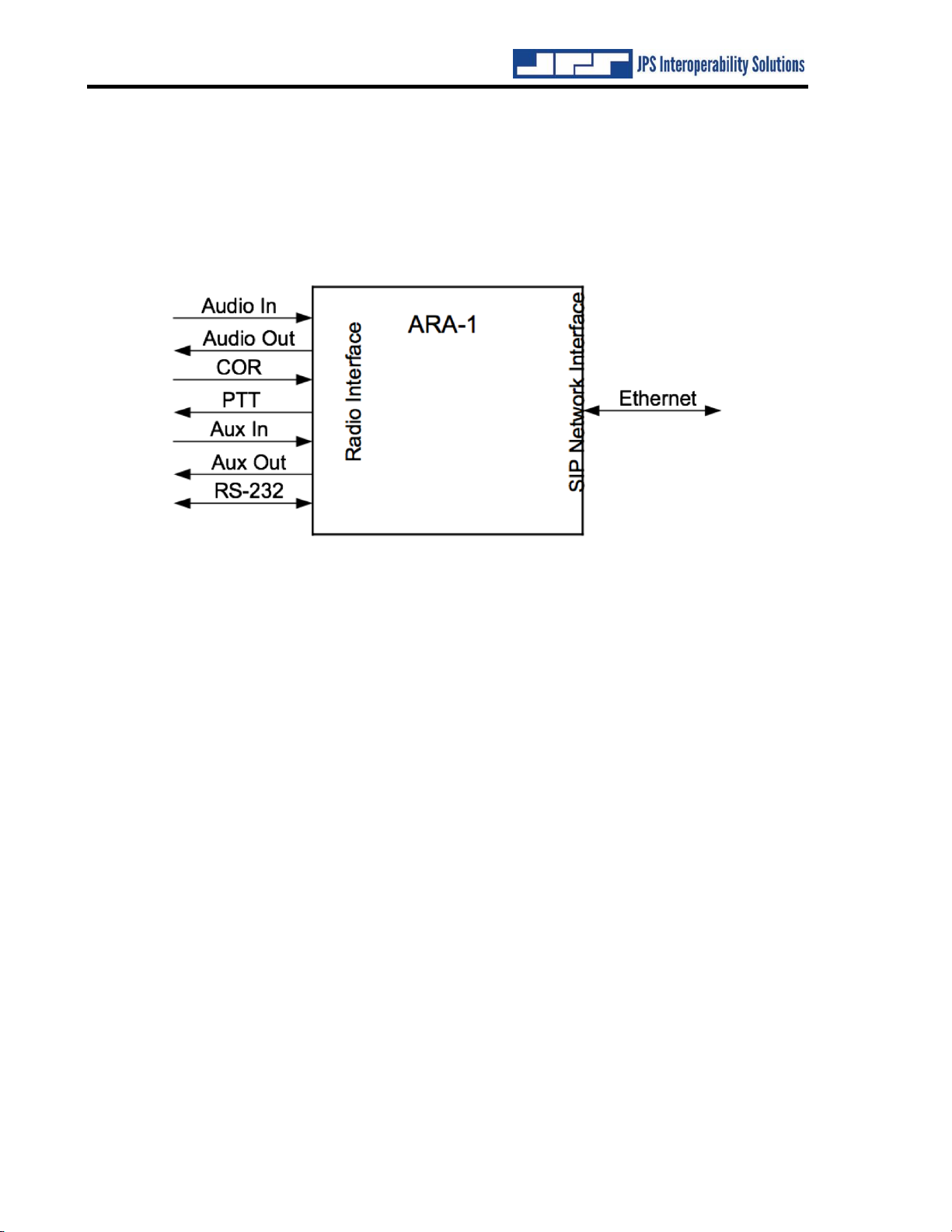
1.2.1 General............................................................................................................................................1-1
1.2.2 SIP Interface....................................................................................................................................1-1
1.2.3 Why SIP?.........................................................................................................................................1-2
1.3 NETWORK DETAILS ..............................................................................................................................1-2
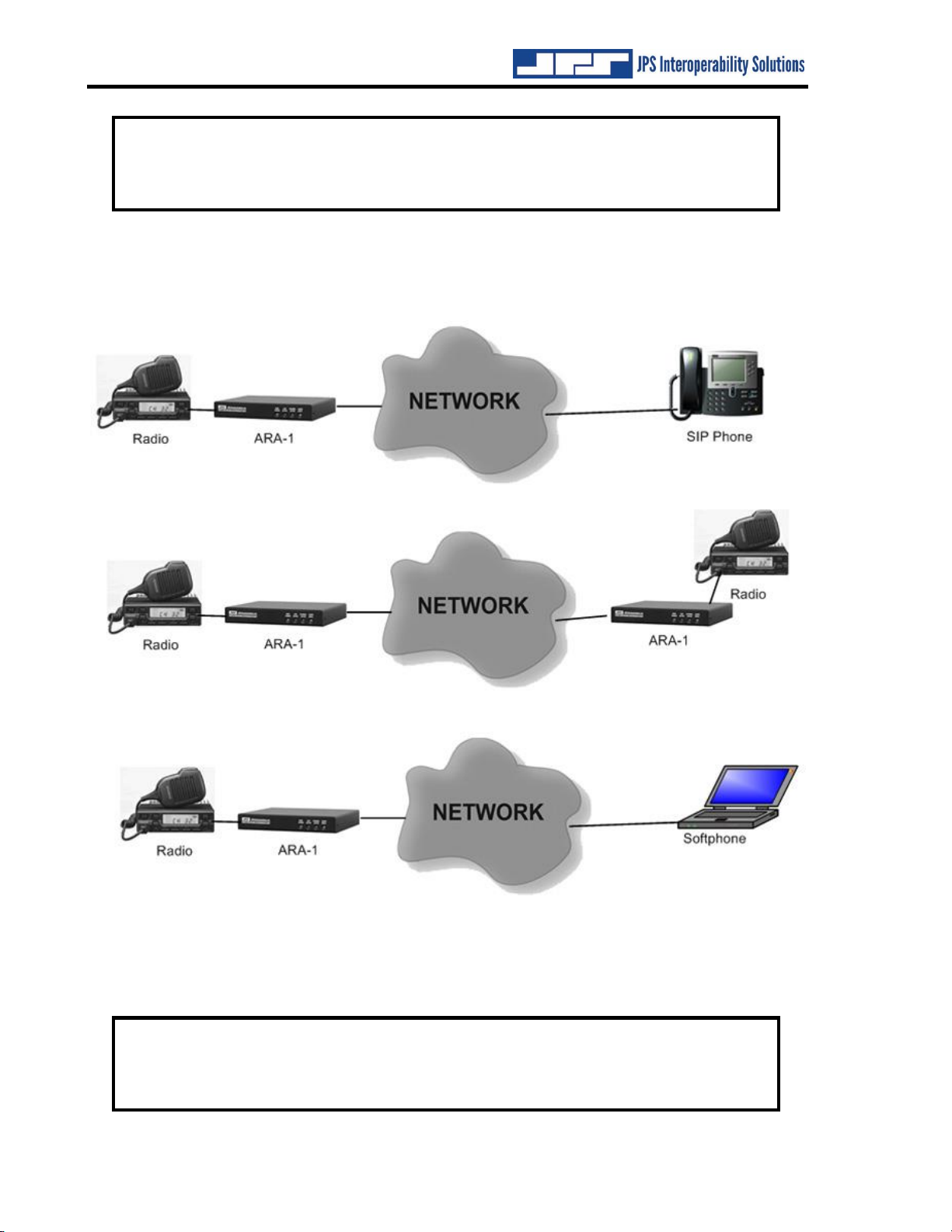
1.4 APPLICATIONS ......................................................................................................................................1-3
1.4.1 Operation within a SIP PBX ...........................................................................................................1-3
1.4.2 Operation Outside of a SIP PBX.....................................................................................................1-4
1.4.3 Use of the ARA-1 with a Repeater System.......................................................................................1-5
1.5 CONNECTION TO DEVICES OTHER THAN A RADIO................................................................................1-6
1.6 INITIATING CONNECTIONS VIA THE ARA-1 AND ASSOCIATED RADIO..................................................1-6
1.6.1 Using a Web Browser......................................................................................................................1-6
1.6.2 Using DTMF ...................................................................................................................................1-6
1.6.3 Using Squelch Breaks......................................................................................................................1-6
1.7 SIP INSTRUCTIONS................................................................................................................................1-6
1.8 COR &PTT SIGNALING IN THE SIP ENVIRONMENT.............................................................................1-7
1.8.1 COR Handling in the SIP Environment...........................................................................................1-7
1.8.2 Deriving COR from the Local Radio...............................................................................................1-8
1.8.3 Pushing the COR Indication across the IP Network .......................................................................1-8
1.8.4 Deriving COR at the Distant Side...................................................................................................1-9
1.9 SPECIFICATIONS..................................................................................................................................1-10
1.10 EQUIPMENT AND ACCESSORIES SUPPLIED ..........................................................................................1-11
1.11 OPTIONAL EQUIPMENT:NOT SUPPLIED ..............................................................................................1-12
2INSTALLATION..........................................................................................................................................2-1
2.1 GENERAL..............................................................................................................................................2-1
2.2 UNPACKING AND INSPECTION...............................................................................................................2-1
2.3 RESHIPMENT OF EQUIPMENT ................................................................................................................2-1
2.4 INSTALLATION OVERVIEW....................................................................................................................2-2
2.5 INSTALLATION CONSIDERATIONS .........................................................................................................2-3
2.5.1 Internal Configuration ....................................................................................................................2-6
2.6 POWER REQUIREMENTS........................................................................................................................2-6
2.7 INSTALLATION CHECKLIST ...................................................................................................................2-6
2.8 REAR PANEL ADJUSTMENTS AND CONNECTORS...................................................................................2-6
2.8.1 DC Input Connector (J6).................................................................................................................2-6
2.8.2 Connection to Radio or Another Four-Wire Device (J7)................................................................2-6
2.8.3 Audio Level Adjustment Potentiometers and Input Test Point........................................................2-7
2.8.4 Network Connection (J3) ................................................................................................................2-8
2.8.5 Serial Port Connection (J4) ............................................................................................................2-8
3CONFIGURATION......................................................................................................................................3-1
3.1 GENERAL..............................................................................................................................................3-1
3.2 CONFIGURATION DETAILS:NETWORK INTERFACE ...............................................................................3-1
3.2.1 Basic Unit Status and Information ..................................................................................................3-2
3.2.2 Network Settings..............................................................................................................................3-3
3.2.3 SIP Settings .....................................................................................................................................3-3
3.2.4 SIP Actions......................................................................................................................................3-7
3.3 CONFIGURATION DETAILS:RADIO INTERFACE .....................................................................................3-8
3.3.1 Radio COR Settings Options...........................................................................................................3-8
3.3.2 Radio PTT Timeout .......................................................................................................................3-10
3.3.3 COR Priority.................................................................................................................................3-10

ARA-1 Operations Manual
4INTEROPERABILITY NOW
3.3.4 Always Pass Audio ........................................................................................................................3-10
3.3.5 Network COR Settings Options .....................................................................................................3-11
3.3.6 Audio Adjustments.........................................................................................................................3-13
3.4 OUTGOING CALL CONFIGURATION .....................................................................................................3-14
3.4.1 Configuring Outgoing Call Initiation via DTMF ..........................................................................3-15
3.4.2 Configuring Outgoing Call Initiation Via COR Cadence..............................................................3-15
3.4.3 Automated Dialing Methods..........................................................................................................3-17
3.4.4 Automatic Redialing......................................................................................................................3-18
3.5 CALL MANAGEMENT ..........................................................................................................................3-19
3.6 ADMINISTRATIVE FUNCTIONS.............................................................................................................3-20
3.6.1 Password Protection .....................................................................................................................3-20
3.6.2 Firmware Upgrade........................................................................................................................3-21
3.6.3 Remote Reboot of the ARA-1 .........................................................................................................3-21
3.7 RESETTING THE ARA-1 TO FACTORY DEFAULTS................................................................................3-21
4OPERATION.................................................................................................................................................4-1
4.1 GENERAL ..............................................................................................................................................4-1
4.2 FRONT PANEL INDICATORS...................................................................................................................4-1
4.2.1 Power LED......................................................................................................................................4-1
4.2.2 Link Active LED ..............................................................................................................................4-1
4.2.3 Channel Active LED........................................................................................................................4-1
4.2.4 Audio Input LED..............................................................................................................................4-1
4.3 ARA-1 OPERATION...............................................................................................................................4-1
4.3.1 Operation at Power-Up...................................................................................................................4-1
4.3.2 Basic Operation...............................................................................................................................4-2
4.3.3 Outgoing Call Initiation ..................................................................................................................4-2
4.3.4 Call Progress Monitoring................................................................................................................4-3
4.3.5 System Information Prompts ...........................................................................................................4-4
5SYSTEM TROUBLESHOOTING ..............................................................................................................5-1
5.1 SYSTEM TROUBLESHOOTING.................................................................................................................5-1
5.2 MISSED FIRST SYLLABLES:RADIO SIDE ...............................................................................................5-1
5.3 MISSED SYLLABLES MID-CONVERSATION:RADIO SIDE .......................................................................5-2
5.4 MISSED FIRST SYLLABLES:NETWORK SIDE..........................................................................................5-2
5.5 MISSED SYLLABLES MID-CONVERSATION:NETWORK SIDE ................................................................5-2
5.6 EXPLANATION:TRUNKED CHANNEL ACQUISITION DELAY...................................................................5-3
5.7 PING PONG............................................................................................................................................5-6
5.8 FALSE KEYING......................................................................................................................................5-6
6ARA-1 FAQ (FREQUENTLY ASKED QUESTIONS) .............................................................................6-1
6.1 GENERAL ..............................................................................................................................................6-1
7INDEX............................................................................................................................................................7-5

ARA-1 Operations Manual
INTEROPERABILITY NOW 5
List of Figures
FIGURE 1-1 ARA-1 BASIC BLOCK DIAGRAM......................................................................................................1-2
FIGURE 1-2 EXAMPLE OF THE ARA-1 IN SIP PBX NETWORK............................................................................1-3
FIGURE 1-3 EXAMPLES OF ARA-1 USE OVER INTERNET....................................................................................1-4
FIGURE 1-4 ARA-1 WITH A REPEATER SYSTEM..................................................................................................1-5
FIGURE 1-5 RADIO TO ARA-1 TO IP NETWORK TO ARA-1 TO RADIO................................................................1-8
FIGURE 2-1 OUTLINE DIMENSIONS .....................................................................................................................2-4
FIGURE 2-2 FRONT AND REAR PANEL VIEWS .....................................................................................................2-5
FIGURE 3-1 STATUS/INFORMATION PAGE...........................................................................................................3-2
FIGURE 3-2 NETWORK SETTINGS PAGE ..............................................................................................................3-3
FIGURE 3-3 SIP SETTINGS PAGE .........................................................................................................................3-4
FIGURE 3-4 SIP ACTIONS PAGE ..........................................................................................................................3-7
FIGURE 3-5 RADIO SETTINGS PAGE ....................................................................................................................3-8
FIGURE 3-6 DIALING PAGE—OUTGOING CALL CONFIGURATION ....................................................................3-14
FIGURE 3-7 CALL MANAGEMENT PAGE............................................................................................................3-19
FIGURE 3-8 ADMINISTRATION PAGE.................................................................................................................3-20
FIGURE 4-1 CALL MANAGEMENT PAGE..............................................................................................................4-3
FIGURE 5-1 “SHOOT”VERSUS “DON’T SHOOT”..................................................................................................5-4
FIGURE 5-2 WHY AUDIO DELAY IS CRUCIAL .....................................................................................................5-5
List of Tables
FIGURE 1-1 ARA-1 BASIC BLOCK DIAGRAM......................................................................................................1-2
FIGURE 1-2 EXAMPLE OF THE ARA-1 IN SIP PBX NETWORK............................................................................1-3
FIGURE 1-3 EXAMPLES OF ARA-1 USE OVER INTERNET....................................................................................1-4
FIGURE 1-4 ARA-1 WITH A REPEATER SYSTEM..................................................................................................1-5
FIGURE 1-5 RADIO TO ARA-1 TO IP NETWORK TO ARA-1 TO RADIO................................................................1-8
FIGURE 2-1 OUTLINE DIMENSIONS .....................................................................................................................2-4
FIGURE 2-2 FRONT AND REAR PANEL VIEWS .....................................................................................................2-5
FIGURE 3-1 STATUS/INFORMATION PAGE...........................................................................................................3-2
FIGURE 3-2 NETWORK SETTINGS PAGE ..............................................................................................................3-3
FIGURE 3-3 SIP SETTINGS PAGE .........................................................................................................................3-4
FIGURE 3-4 SIP ACTIONS PAGE ..........................................................................................................................3-7
FIGURE 3-5 RADIO SETTINGS PAGE ....................................................................................................................3-8
FIGURE 3-6 DIALING PAGE—OUTGOING CALL CONFIGURATION ....................................................................3-14
FIGURE 3-7 CALL MANAGEMENT PAGE............................................................................................................3-19
FIGURE 3-8 ADMINISTRATION PAGE.................................................................................................................3-20
FIGURE 4-1 CALL MANAGEMENT PAGE..............................................................................................................4-3
FIGURE 5-1 “SHOOT”VERSUS “DON’T SHOOT”..................................................................................................5-4
FIGURE 5-2 WHY AUDIO DELAY IS CRUCIAL .....................................................................................................5-5

ARA-1 Operations Manual
6INTEROPERABILITY NOW
Glossary
ATA
Analog Telephone
Adapter
A device that interfaces an analog telephone to a SIP
network.
COR
Carrier Operated Relay
A signal from a receiver that indicates when a carrier or
signal is being received and the receiver is unsquelched.
Sometimes called COS (Carrier Operated Squelch).
COS
Carrier Operated
Squelch
See COR.
DHCP
Dynamic Host
Configuration Protocol
A method of automatically assigning a dynamic IP
address to an Ethernet device at startup time. DHCP
conserves IP addresses in networks among devices that
do not stay permanently connected.
DSP
Digital Signal Processor
A type of microprocessor, optimized for signal
processing functions.
IP
Internet Protocol
A protocol designed to allow communications between
computers on different networks.
LAN
Local Area Network
A group of computers and associated devices that share a
common communications line, typically within a small
geographic area. Compare with WAN.
PBX
Private Branch
Exchange
A private telephone system serving an office, campus, or
similar setting.
PTT
Push-to-talk
A signal to a radio that activates the transmit function
and controls the actual transmission of radio frequency
energy over the air. Also called a keyline.
SIP
Session Initiation
Protocol
A protocol for initiating, modifying, and terminating
multimedia sessions.
SIP Phone
A telephone that uses SIP as its signaling protocol.
Soft Phone
A computer program that provides SIP Phone capability.
TCP
Transmission Control
Protocol
An additional layer to the Internet Protocol, which
ensures delivery of packets sent across the network. It
can resolve situations such as lost packets or packets
arriving out of order. Compare with UDP.
UDP
User Datagram Protocol
An additional layer to the Internet Protocol, which does
not ensure delivery of packets, but which offers more
speed and lower transmission overhead than TCP.
URI
Universal Resource
Identifier
A string of characters that identify (name) a resource to
facilitate interactions over a network.
VoIP
Voice over Internet
Protocol
A method of sending voice communications across a
digital network.
WAN
Wide Area Network
A network that is spread out over a wide geographic
area, such as around a city or state. It may include other
public or shared networks. Compare with LAN.

INTEROPERABILITY NOW 1-1
1General Information
1.1 Scope
This instruction manual provides the information necessary to install and operate the ARA-1 TM
Radio-to-SIP Interface.
1.2 Description
The JPS Interoperability Solutions ARA-1 Radio-to-SIP Interface is a network device used for
interfacing radio equipment to SIP networks, therebyextending the coverage and capability of
these networks. It is comparable to an ATA (analog telephone adapter), which allows a standard
telephone to operate on a SIP network; the ARA-1 provides the same capability to a radio. The
ARA-1 makes special provision for the differences between radios and telephones. In particular,
the half-duplex nature of radios and the control signals they require are accommodated by the
ARA-1.
Designed for years of continuous operation in mission-critical applications and remote locations,
the ARA-1 has no moving parts and requires no periodic shutdown or maintenance. Startup upon
power on is typically less than 10 seconds.
1.2.1 General
The ARA-1 provides a seamless interface between a radio and an IP-based network using SIP.
This brings to existing SIP networks all the features inherent in a radio system, including the
ability to wirelessly reach otherwise inaccessible areas. For example, an ARA-1 can be used with
an LMR system to extend the SIP Network into areas of rugged terrain, across bodies of water,
or into tunnels.
The ARA-1 also provides to radio networks all the features available with SIP. These include
interoperable communication among disparate radio systems that is as easy as creating a typical
PBX conference call and also other PBX features such as Call Logging, Call Forwarding, and
Call Recording.
1.2.2 SIP Interface
The SIP side of the ARA-1 assigns its associated radio a unique extension that can easily be
dialed using any IP phone, softphone, or other voice communications device associated with the
SIP PBX. Any number of radios, SIP Phones, or other audio devices in the network can be
conferenced together by the SIP PBX.

ARA-1 Operations Manual
1-2 INTEROPERABILITY NOW
Alternatively, the ARA-1 can assign an IP address to its associated radio for communications
over any IP-based network or the Internet with another SIP-enabled device (such as a SIP Phone,
a softphone, or another radio/ARA-1 pair). The radio side of the interface makes full use of the
extensive suite of digital signal processor algorithms, hundreds of interface cables, and numerous
problem-solving techniques that JPS has evolved during more than a decade as the market leader
in radio interoperability.
Figure 1-1 ARA-1 Basic Block Diagram
1.2.3 Why SIP?
The main goals of modern communications system design include: convergence of voice, data,
and video; standards-based, open protocols; and individual IP addresses for all end devices.
Session Initiation Protocol, SIP, is widely seen as the preferred pathway to achieving these goals.
SIP is a signaling protocol used to create, manage, and terminate sessions in an IP-based network.
A session could be a simple two-party call or a multimedia conference session. SIP focuses on
the setup, modification, and termination of sessions allowing versatility of the format and content
of the data being shared. Since SIP is a standards-based, open protocol, SIP system operators can
pick and choose among third-party vendors when selecting existing or future applications to add
to their systems. This avoids the single-vendor “lock-in” that can occur with closed proprietary
protocols. JPS also sells a similar device, the NXU-2A, which uses a proprietary protocol that
JPS created for best operation with radio networks.
1.3 Network Details
The ARA-1 is a 10/100BASE-T Ethernet device, and each unit has a unique Ethernet address
and an RJ-45 physical interface jack. A 10/100BASE-T device operates at either 10 or 100 Mbps
and interconnects to an Ethernet hub or switch using standard CAT 5 twisted pair cable. The
maximum cable length between an ARA-1 and its hub port is 100 meters. With the right
connective equipment (recommended or supplied by JPS), the ARA-1’s Ethernet port can be
linked with virtually any LAN, WAN, or the Internet, no matter which topology orcabling system
is in use.

ARA-1 Operations Manual
INTEROPERABILITY NOW 1-3
1.4 Applications
The ARA-1 can be used either as part of a SIP PBX or without one. Often the radio associated
with the ARA-1 will be part of a repeater system. The features of each of these configurations
are explained in the following sections. It is important to read all three of the following sections
to fully understand the application of radios to SIP networks.
1.4.1 Operation within a SIP PBX
Figure 1-2 illustrates a basic ARA-1 application within a SIP PBX network. The PBX (typically
a software application running on a server) assigns extensions (associated to the IP addresses) to
each of the communications devices within the system. There can be any number of the end-user
devices (Sip Phones, softphones, analog phone/ATA pairs, or radio/ARA-1 pairs) in the PBX.
When a SIP Phone user wants to place a call to another SIP Phone, he or she can simply dial that
phone’s extension. The same process is followed to place a call to the radio: simply dial the ARA-
1’s extension. The SIP Phone user does not need to understand the esoterica of basic radio
operation; this is handled by the ARA-1.
Figure 1-2 Example of The ARA-1 in SIP PBX Network
Similarly, calls to the radio can be placed by the softphone or the analog telephone, interfaced by
the ATA, simply by entering the extension assigned to the ARA-1.
The SIP PBX can provide a multitude of functions and features that expand and enhance the
communications process. These include conferencing, voice mail, call logging, call forwarding,
and essentially any other feature available with a commercial telephone service. Because the
ARA-1 is based on the open-source SIP protocol, a wide range of PBX features are available
from a wide range of sources.

ARA-1 Operations Manual
1-4 INTEROPERABILITY NOW
NOTE: The PBX conferencing function, with multiple radio/ARA-1 pairs, provides
network-based interoperability between disparate radio systems. For example,
an 800 MHz trunked radio can be conferenced together with a P25 digital radio
and a VHF conventional radio.
1.4.2 Operation Outside of a SIP PBX
The ARA-1 can also be used without a SIP PBX, but without the features provided by the PBX,
so that only one-to-one connections are possible. Three variations are illustrated in Figure 1-3.
The network employed can be any type of IP-based network, including the Internet.
Figure 1-3 Examples of ARA-1 Use Over Internet
The first setup in Figure 1-3 shows a connection between a SIP Phone and a radio. Without the
extensions provided by the PBX, the SIP Phone “dials” the IP address of the ARA-1. See Section
1.6 for an overview of how to initiate connections via the ARA-1 rather than by the SIP Phone.
NOTE: The radio shown in the first illustration in Figure 1-3 may be set as
“receive-only” and used to monitor information and pass it over the network. For
example, it may be receiving local weather or traffic reports or scanning
frequencies set aside for public safety use.

ARA-1 Operations Manual
INTEROPERABILITY NOW 1-5
The second setup in Figure 1-3 shows a pair of radio systems connected via the ARA-1
technology and the network. These radio systems may be on opposite sides of the country, or
they may be collocated, but on different frequencies or bands.
The third setup shows a connection between a softphone and a radio through the ARA-1. This
operation is identical to the SIP Phone application.
1.4.3 Use of the ARA-1 with a Repeater System
It is important to note that the ARA-1 makes a connection not to a single radio or single radio
user, but to an entire radio system. All signals picked up by the radio are relayed through the
ARA-1, and more importantly, transmissions through the ARA-1 are sent to all radios that can
pick up this transmission.
In many cases, the ARA-1 and radio will be used within a repeater system. The radio associated
with the ARA-1 will create an RF link to a repeater system as illustrated in Figure 1-4.
Figure 1-4 ARA-1 with a Repeater System
Whenever the SIP Phone user connected to the radio/ARA-1 pair speaks, the radio transmits.
This transmission is picked up by the repeater system, which retransmits it to all the mobile and
handheld radio users in the system. Similarly, all of their transmissions are retransmitted by the
repeater system to be received by all system users, including the radio associated with the ARA,
so all of this traffic can be heard by the SIP Phone user.

ARA-1 Operations Manual
1-6 INTEROPERABILITY NOW
This concept applies to both trunked and conventional repeater systems. Note that no changes to
the repeater system are required, hence there is no installation or other downtime involved with
using the ARA-1 to create a single SIP network connection to the system, or to use multiple
ARA-1s to conference two or more radio systems together.
1.5 Connection to Devices Other Than a Radio
The ARA-1 contains all of the interface features necessary for a competent interface between a
radio and a SIP network. These features also provide a seamless interface of other four-wire
devices such as an audio console.
1.6 Initiating Connections via the ARA-1 and Associated Radio
So far calls to a radio through the ARA-1 have been described. There are three methods for
initiating a call from the radio/ARA-1 end of the connection. Each of these methods is described
in full detail in Section 4, Operation.
1.6.1 Using a Web Browser
Simply browse to the ARA-1’s IP address, select the Call Management page, enter the SIP
address or extension, and click Connect.
1.6.2 Using DTMF
If your radio has a DTMF keypad, there are two options that can be used to initiate connections
to an IP address or a PBX extension. DTMF input not terminated by a pound (#) digit invokes an
internal “speed dial” calling guide that is set up within the ARA-1; this calling guide associates
incoming DTMF sequences with the destination IP address or extension.
Whenever the DTMF input is terminated by the pound digit, the ARA-1’s Pound Terminated
Dialing feature dials the received DTMF sequence (except for the pound digit). This allows a
radio user with a DTMF keypad to dial any number or extension just as the user would dial a
regular telephone.
1.6.3 Using Squelch Breaks
The ARA-1 can use the COR (unsquelched condition) input from its associated radio as a signal
from radio system users that they want to make or end a call. The radio users in the field key and
unkey their radios at a specific cadence (user-programmable). For example, the required cadence
may be four key/unkey sequences at the specified rate (three or five will not trigger a response).
The radio associated with the ARA-1 unsquelches and re-squelches at the same cadence, and
passes this cadence on to the ARA-1. When the required cadence is detected, the ARA-1 initiates
a call to a pre-defined SIP address or extension. A COR Cadence can also be used to terminate
the call.
1.7 SIP Instructions
This manual does not attempt to familiarize the reader with SIP fundamentals. SIP is an open
protocol and there are many references that explain how to best make use of it. The ARA-1 is
fully compliant with the SIP protocol.

ARA-1 Operations Manual
INTEROPERABILITY NOW 1-7
1.8 COR & PTT Signaling in the SIP Environment
Most radio systems are either simplex or half duplex, the important aspect to remember for both
types is that only one person can be heard at a time. With full duplex systems, all parties to a
conversation may be heard simultaneously: a telephone system is a good example. Most JPS
interoperability equipment can accommodate both types of systems, but both parties of a
conversation must be using full duplex equipment for either party to be able to simultaneously
talk and listen.
The same is true of interoperable communications using SIP; many SIP devices are capable of
Full Duplex operation (as are most phone-related voice communications devices). However,
when patched to a half-duplex radio, the conversation is limited to Half Duplex.
COR: A signal that tells when a radio (or other communications device) is
receiving a valid signal (an output from the device).
PTT: A signal that tells a radio (or other communications device) that a valid
signal is being sent to be transmitted (an input to the device).
Full Duplex: System users can simultaneously talk to and listen to other parties
of the communications system.
Simplex or Half Duplex: Only one system user can be heard at a time.
This section will help explain how these concepts affect the set up configuration options. More
details on the options in Section 2.
1.8.1 COR Handling in the SIP Environment
There are three basic components:
•How the ARA-1’s radio interface determines that its associated radio is unsquelched-
how the “Active COR” condition is determined. Also called “Deriving COR.”
•How this signal is sent over the network by the SIP Protocol
•How the SIP device on the “other side” of the network knows that valid audio is being
sent to it.

ARA-1 Operations Manual
1-8 INTEROPERABILITY NOW
1.8.2 Deriving COR from the Local Radio
Within the JPS ARA-1 SIP-to-Radio interface, there are two options at the radio interface for
deriving COR (determining that the associated radio is unsquelched).
See Figure 1-5 below; with ARA-1s on both sides of the link, it illustrates all aspects of COR/PTT
signaling. To simplify the explanation, consider Radio A the Local Radio; Radio B will be
referred to as the Distant Radio.
Figure 1-5 Radio to ARA-1 to IP Network to ARA-1 to Radio
Currently we’re discussing how the Local ARA-1 determines that the Local Radio cabled to it is
unsquelched. The options include:
•A Hardwired COR signal –some radios supply a COR output line.
•VOX: Active COR is triggered by any audio input above a configurable threshold.
For radio interface cables supplied by JPS, the Radio Application Note supplied with the cable
will explain which is best for the associated radio model.
1.8.3 Pushing the COR Indication across the IP Network
The Local ARA-1 in Figure 1-5 has various options for making the Distant ARA-1 aware that
the local radio is unsquelched. These include:
•RTP Header: IP packets include an RTP extension header that JPS created for this
purpose. When the extension is detected by the distant ARA-1, it knows the local radio
is unsquelched. The local ARA-1 will send its COR status over the network as part of the
RTP extension header if its Send Radio COR/AUX Status function is enabled.
•Silence Suppression: Very simply described –send audio packets to the distant ARA-1 if
the local radio is unsquelched, and if not, don’t send any. Silence suppression is invoked
when the Silence Suppression function is enabled via the SIP Settings web page.
These Active COR indicators are best understood in terms of how they are applied by the Distant
ARA-1. Operation at this unit is more complex as the Distant ARA-1 must also be able to
function properly if there are “non-JPS” devices playing the part of the Local ARA-1. This is
vital because many SIP devices, such as the SIP VoIP phones and computer-based Softphones
are Full Duplex, while radio systems are Half Duplex. If not handled properly, a Full Duplex
device that’s linked to a distant radio could cause that radio to remain continuously keyed. This
is not likely to be a desirable condition.
ARA-1
Local
Radio A
Local ARA-1
Distant
Radio B
Distant

ARA-1 Operations Manual
INTEROPERABILITY NOW 1-9
1.8.4 Deriving COR at the Distant Side
The options are different at the network interface; that is - how an ARA-1 determines that the
radio at the other side of the network is unsquelched. These are the options for deriving COR at
the unit’s network interface – how, in Figure 1-5, the distant ARA can determine that the local
radio is unsquelched:
•VOX: triggered by any audio input (audio coming over the network) above an adjustable
threshold level.
•VMR: triggered by audio input ONLY if that audio has content (again above an adjustable
threshold), that correlates to human speech sounds and patterns. VMR can help prevent
false transmitter activation from background noise on the SIP connection (such as
someone breathing heavily into a SIP Phone handset mouthpiece, or someone using a SIP
Phone in a high ambient noise environment)
[Note: VMR requires significant processing resources. This is why VMR is supported
only on the network side and not on the radio side.]
•RTP Header: makes use of an RTP extension header that JPS created for this purpose.
This is useful when there are JPS SIP devices at both ends (or the use of the SIP extension
header has been built in to another vendor’s equipment).
The JPS SIP devices also allow combinations of the above; these are useful when there
may be different types of SIP devices in the system. When a combination is invoked - for
example “RTP Header + VMR” - the ARA-1 will use the RTP Header if it’s available
and the VMR function when it’s not.
•Packet COR: Heeding the note below, this is the preferred method, and the combination
of Silence Suppression and Packet COR was made part of the NIST BSI specification
(JPS SIP interfaces are BSI compliant). With this method, the Local ARA -1, upon
determining that its associated local radio is squelched, will discontinue sending audio
packets (Silence Suppression). Regardingthe Distant ARA's PTT function, it will activate
PTT to the distant radio only while receiving audio packets from the network.
Note: Packet COR should only be used if all SIP devices on the network use Silence
Suppression. If a link is made to any SIP device configured otherwise, that distant device
will continue to send audio packets over the network even when there is no valid audio
signal, and the PTT function of anARA-1 set to Packet COR will therefore stay activated,
holding the local radio in transmit mode.

ARA-1 Operations Manual
1-10 INTEROPERABILITY NOW
1.9 Specifications
Table 1-1 Specifications
Radio RX Audio Input
Input Impedance
Balanced 47k ohms, transformer coupled
Input Level
Incoming signals adjustable from –30 to +11 dBm to set 0 dBm nominal input;
+15 dBm clipping; +20 dB boost configurable
Frequency Response
10 Hz to 3600 Hz +/- 2dB
Radio TX Audio Output
Output Impedance
Unbalanced 600 ohms, AC Coupled
Output Level
Adjustable from –30 to +11 dBm, 0 dBm nominal factory default; +9 dBm
clipping into a 600 ohm load
Frequency Response
10 Hz to 3350 Hz +/- 2dBm
Distortion
0.5% or less (excepting Vocoder)
Radio COR and AUX Inputs
Input Impedance
47k ohm pull-up to +5V
Polarity
COR: Selectable active low or active high; AUX Inputs: Active low
Threshold
+2.5V nominal
Protection
Up to + 100 VDC
Radio PTT and AUX Outputs
Output Type
Open drain, 47k ohm pull-up to +5V
Maximum Sink Current
100 mA
Max Open Circuit Voltage
+60 VDC
Network Interface
Interface Type
10/100BASE-T Ethernet, 10 or 100 Mbps; RJ-45 Connector
Protocols
SIP, SDP, RTP, STUN
Audio Vocoder
Selectable, 13 or 64 Kbps data rate
General/Environmental
Programming/Configuration
Web, Telnet, or RS-232 Interface
Front Panel
Power, Link Active, Channel Active, and Audio Level LEDs
Rear Panel
Audio/Data, Serial, Network, and Power Connectors
Audio/Data Connector
DB-15 Female
Input Power (12 VDC Nom)
+11 to +15 VDC at 0.5A max. 12VDC (wall-cube supplied)
Power Connector
Coaxial Jack, 2.5 mm ID, 5 to 5.5 mm OD; Center Pin Positive; Reverse
Polarity Protected
Size and Weight
1.3”H x 8.3”W x 6.7”D (3.3 x 21.1 x 17.0 cm); 1.1 lbs. (0.5kg)
Temperature
Operating: -20 to +60 degrees C; Storage: -40 to +85 degrees C
Humidity
Up to 95% at 55 degrees C
Regulatory Compliance
FCC part 15
RFI Emissions for USA

ARA-1 Operations Manual
INTEROPERABILITY NOW 1-11
1.10 Equipment and Accessories Supplied
Table 1-2 Equipment and Accessories Supplied –Standard Version
ARA-1 Shipping Level - JPS P/N 5060-800000
Quantity
Item
JPS P/N
1
ARA-1 Final Assembly
Includes the ARA-1 enclosure with the ARA-1 PCB Assembly
5060-801000
1
12V DC Power Supply [100 to 240 VAC, 47-63 Hz]
1620-240061
1
Accessory Kit
5060-800150
Consisting of:
Qty Part Number Description
1 0313-070000 Network Cable, 6 ft.
1 0313-080515 Audio Crossover Adapter
(for use with JPS radio interface cables)
Table 1-3 Equipment and Accessories Supplied –European Version
ARA-1 Shipping Level - JPS P/N 5060-810000
Quantity
Item
JPS P/N
1
ARA-1 Final Assembly
Includes the ARA-1 enclosure with the ARA-1 PCB Assembly
5060-801000
1
12V DC Power Supply [100 to 240 VAC, 47-63 Hz]
Includes European Adapters
1620-120600
1
Accessory Kit
5060-800150
Consisting of:
Qty Part Number Description
1 0313-070000 Network Cable, 6 ft.
1 0313-080515 Audio Crossover Adapter
(for use with JPS radio interface cables)

ARA-1 Operations Manual
1-12 INTEROPERABILITY NOW
1.11 Optional Equipment: Not Supplied
Table 1-4 Optional Equipment - Not Supplied
Description
JPS P/N
ARA-1 Operation and Maintenance Manual, printed and bound
5060-800200
Note: This manual available for download at no charge from jpsinterop.com website
Generic Radio Interface Cable; unterminated at radio end; 15 ft.
5961-291115
Interface cables for a very wide range of commercial radios are available for purchase.
Email JPS or consult the JPS Interoperability Solutions website for a listing:
Email: sales@jpsinterop.com / support@jpsinterop.com
www.jpsinterop.com
End of Section 1

INTEROPERABILITY NOW 2-1
2Installation
2.1 General
This section provides the instructions for unpacking, inspection, installation, and setup. Also
included are directions for reshipment of damaged parts or equipment.
2.2 Unpacking and Inspection
After unpacking the unit, retain the carton and packing materials until the contents have been
inspected and checked against the packing list. If there is a shortage or any evidence of damage,
do not attempt to use the equipment. Contact the carrier and file a shipment damage claim. A
full report of the damage should also be reported to the JPS Customer Service Department. The
following information should be included in the report:
➢Order Number
➢Equipment Model and Serial Numbers
➢Shipping Agency
➢Date(s) of Shipment
The JPS Interoperability Solutions Customer Service Department can be reached by phone at
of this information, JPS will arrange for repair or replacement of the equipment.
2.3 Reshipment of Equipment
If it is necessary to return the equipment to the manufacturer, an RMA (Returned Material
Authorization) number must first be obtained from JPS. This number must be noted on the
outside of the packing carton and on all accompanying documents. When packing the unit for
reshipment, it is best to use the original packaging for the unit; if this is not possible, make sure
that adequate packing material is used to prevent excessive shocks during transport and handling.
Shipment should be made prepaid consigned to:
JPS Interoperability Solutions
Customer Service Department
5800 Departure Drive
Raleigh, North Carolina 27616
USA
Plainly, mark with indelible ink all mailing documents as follows:
GOODS RETURNED FOR REPAIR
Mark all sides of the package:
FRAGILE - ELECTRONIC EQUIPMENT
Inspect the package prior to shipment to be sure it is properly marked and securely wrapped.

ARA-1 Operations Manual
2-2 INTEROPERABILITY NOW
2.4 Installation Overview
NOTE: ARA-1 installation requires knowledge of Ethernet network
fundamentals as well as a basic understanding of IP (Internet Protocol). As with
any network-connected device, improperly configuring and installing the ARA-1
could disrupt proper network operation. Please seek the assistance of your
network administrator or other knowledgeable person if you are unsure about
how your network is configured.
Four steps are needed to properly install the ARA-1. These steps are:
1. Determine the desired IP address, subnet mask, and (if applicable) the gateway
address for the unit. You may have to contact the network administrator for your
organization to obtain this information.
NOTE: Operation of the ARA-1 is not possible without this information.
2. Provide the proper primary power for the unit.
NOTE: Use only the Class 2 power supply provided with the equipment.
REMARQUE: Utilisez seulement la Class 2 de la generation electrique qui est
inclus avec l'equipement.
. 3. Interconnect the unit with the communications system via the ARA-1's rear panel
connectors. J7 provides the audio and control lines necessary to interface the ARA-1
to your audio equipment. Radio interface cables for most common makes and models
can be purchased from JPS Interoperability Solutions.
4. Configure the unit’s operational parameters per Sections 2.8.3 (rear panel audio level
adjustments) and 3.2 (system configurations set by web browser).
Table of contents
Other JPS Recording Equipment manuals