CHD Elektroservis 7-401 User manual
7
Module 7-401 v. 1.0
USER GUIDE
© 2014 CHD Elektroservis

Tunable Noise / S&H Generator
Module 7-401 v. 1. 0
Copyright © 2014 CHD Elektroservis. All rights reserved.
No part of this publication may be reproduced in any form without the written permission of CHD Elektroservis.
2
Content
page
1. Main features . . . . . . . . . . . . . . . . . . . . . . . . . . . . . . . . 3
2. Module functions . . . . . . . . . . . . . . . . . . . . . . . . . . . . . . . 4
3. Connection the module to the system . . . . . . . . . . . . . . . . . . . . . . 5
4. Noise generator . . . . . . . . . . . . . . . . . . . . . . . . . . . . . . . . 5
4.1. Noise spectrum manual control . . . . . . . . . . . . . . . . . . . . . . . . . 5
4.2. Noise spectrum external control . . . . . . . . . . . . . . . . . . . . . . . . 5
4.3. Noise spectrum modulation . . . . . . . . . . . . . . . . . . . . . . . . . . 6
5. Sample & Hold generator . . . . . . . . . . . . . . . . . . . . . . . . . . . 6
6. Technical parameters . . . . . . . . . . . . . . . . . . . . . . . . . . . . . 7
7. Warranty conditions . . . . . . . . . . . . . . . . . . . . . . . . . . . . . . 7
This manual and other documentation are also available at : www.chd-el.cz
Manufacturer :
CHD Elektroservis
Nad kundratkou 27, 19000 Praha 9, Czech Republic
info@chd-el.cz
www.chd-el.cz

Tunable Noise / S&H Generator
Module 7-401 v. 1. 0
Copyright © 2014 CHD Elektroservis. All rights reserved.
No part of this publication may be reproduced in any form without the written permission of CHD Elektroservis.
3
1. MAIN FEATURES
Noise signal is unable from white noise, through pink noise up to harsh digital sound.
The tuning is not based on usual noise filtering – special circuit is used.
Noise spectrum is controllable manually or by external CV (e.g. keyboard CV, envelope
generator, etc.)
Noise spectrum can be also modulated by external (LFO) or internal modulation source (the
noise itself or Sample & Hold).
Independent Sample & Hold generator with external triggering.
Stainless steel front panel.
Pure analogue circuitry (no DSP technology is used).
Fully hand-made – each module is tested and adjusted individually.
OUR MISSION
Do things different
Always offer something unique and innovative not available on the market so far.
No compromises in the circuitry design
Don’t give up the sound quality for cost driven compromises.
Classic design and hi-end components
For long live and better serviceability of the devices.
Hand made in Europe
Each unit is hand made and individually adjusted for highest quality control.
Tunable Noise / S&H Generator
Module 7-401 v. 1. 0
Copyright © 2014 CHD Elektroservis. All rights reserved.
No part of this publication may be reproduced in any form without the written permission of CHD Elektroservis.
4
2. MODULE FUNCTIONS
Tunable Noise + S&H Generator is designed for Eurorack modular synthesizer systems. All controls,
signal inputs and outputs are located on the front panel (see Fig. 1). Inputs and outputs use standard
mono 3,5 mm (1/8“) mini-jack patch connectors.
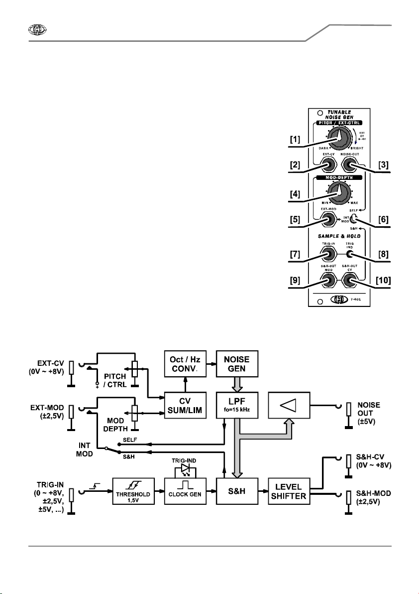
Fig. 1 – module front panel
[1] PITCH / EXT-CTRL – noise spectrum control / ext CV level control
[2] EXT-CV – external control voltage input
[3] NOISE-OUT – noise generator audio output
[4] MOD-DEPTH – noise modulation depth control
[5] EXT-MOD – external modulation control voltage input
[6] INT-MOD – internal modulation source switch
[7] TRIG-IN – trigger signal input for S&H
[8] TRIG-IND – S&H trigger indicator
[9] S&H-OUT-MOD – S&H output – modulation signal
[10] S&H-OUT-CV –S&H output – CV signal
The module includes two individual function blocks: tunable noise generator and S&H (see Fig. 2).
Fig. 2 – Block Scheme

Tunable Noise / S&H Generator
Module 7-401 v. 1. 0
Copyright © 2014 CHD Elektroservis. All rights reserved.
No part of this publication may be reproduced in any form without the written permission of CHD Elektroservis.
5
3. CONNECTION THE MODULE TO THE SYSTEM
Fig. 3 – Bus board connection
To connect the module, plug carefully the supplied
ribbon cable into the bus socket of your modular
case. The colored marking of the ribbon cable
must be at the bottom of the bus connector!
Failure to check this may result in the module or
case PSU damage! (module is not protected against
permanent incorrect polarity).
The module uses ±12V of the system only (pins Nr.
1 to 10), GATE, CV and +5V signals are not used
(see Fig. 3).
4. NOISE GENERATOR
The noise generator is tunable – i.e. various noise color (spectrum) can be set (see Fig. 4). This can
be manually set by PITCH / EXT-CTRL [1] potentiometer or by external control voltage (CV) from
EXT-CV [2] input. The noise basic tuning can be further modulated by internal or external control
voltage modulation source. The noise spectrum can be continuously adjusted from white noise
(BRIGHT) through pink to harsh digital interference-like sound (DARK) – see Fig. 4.
Note: Control voltage for noise generator (V/oct) is converted by exponential amplifier (to V/Hz), so
the noise color change is balanced and continuous for human ears in the entire tune range.
Fig. 4 – Noise signal tune range
Noise generator output audio-signal is available at NOISE-OUT [3] output. The output voltage
amplitude is in range of ±5 V.
4.1. NOISE SPECTRUM MANUAL CONTROL
If the EXT-CV [2] input is not used, the generator can be tuned manually in the whole range (DARK
to BRIGHT) by PITCH / EXT-CTRL [1] potentiometer.

Tunable Noise / S&H Generator
Module 7-401 v. 1. 0
Copyright © 2014 CHD Elektroservis. All rights reserved.
No part of this publication may be reproduced in any form without the written permission of CHD Elektroservis.
6
4.2. NOISE SPECTRUM EXTERNAL CONTROL
External control voltage (CV) is connected to EXT-CV [2] connector. For full tune range 0 to +4V
minimal control voltage is required. To adjust the tune range to actually used control voltage use
PITCH / EXT-CTRL [1] potentiometer (see Fig. 5).
Fig. 5 – PITCH / EXT-CTRL settings for various control voltages
Note: The above described adjustment of the external control voltage range is suitable e.g. for MIDI
/ CV converters with output voltage 0 to 4 V.
4.3. NOISE SPECTRUM MODULATION
The noise spectrum can be modulated. The required modulation depth is set by MOD-DEPTH [4]
potentiometer. The modulation source can be either internal or external.
If the EXT-MOD [5] input is not used, the internal modulation is used then. The noise signal (self
modulation) or S&H output can be set as an internal modulation source by INT-MOD [6] switch.
If there is a patch lead inserted in EXT-MOD [5] connector, internal modulation source is
automatically disconnected and the noise is modulated by the external control voltage source.
Minimal required modulation signal level for full modulation range is ±2,5 V
PP
. External modulation
source can have any shape and frequency up to ca 4 kHz.
5. SAMPLE / HOLD GENERATOR
Random signal S&H (Sample / Hold) is derived from the noise generator. Triggering (change
frequency) is controlled by external signal connected to EXT-TRIG [7] input. The frequency is
indicated by red LED TRIG-IND [8] blinking.
External trigger signal can be of any shape and its level can be in full control voltage range (e.i.. ±12
V
PP
). Clock impulses, LFO signals or even acoustic signal (with frequency up to ca 4 kHz) can be used
thus. The change event at the S&H-OUT outputs is defined by achieving the + 1,5 V threshold level
of the lead-in edge of the trigger signal.
The S&H generator has two independent outputs. Both outputs provide same signal, each with
different level. S&H-OUT-MOD [9] output (Modulation) generates ±2,5 V
PP
. S&H-OUT-CV [10] output
(Control Voltage) generates 0 to +8 V voltage levels.
Note: The S&H-OUT-MOD [9] output can be also used as audio output. Very atypical sound is
produced if an acoustic signal is used as trigger signal.

Tunable Noise / S&H Generator
Module 7-401 v. 1. 0
Copyright © 2014 CHD Elektroservis. All rights reserved.
No part of this publication may be reproduced in any form without the written permission of CHD Elektroservis.
7
6. TECHNICAL PARAMETERS
Mechanical dimensions
Module width : 8 HU (40,3 mm)
Module height : 3 U (128,5 mm)
Module site depth : 53 mm (without power supply cable)
Power supply
Supply voltage : ±12 V from the system bus
Current requirement : max +45 mA / +12 V
max –25 mA / -12 V
Inputs / outputs
Inputs : EXT-CV 0 to min +4 V pro for full driving / Z
IN
= 10 kΩ
EXT-MOD min ±2,5 V
PP
for full driving / Z
IN
= 100 kΩ
TRIG-IN max ±12 V
PP
, threshold +1,5 V, hysteresis 0,3V / Z
IN
= 40 kΩ
Outputs : NOISE-OUT ±5 V
PP
/ Z
OUT
= 200 Ω
S&H-MOD ±2,5 V
PP
/ Z
OUT
= 200 Ω
S&H-CV
0 to +8 V / Z
OUT
= 200 Ω
Accessory
Ribbon power supply cable with 10 / 16 pin connectors, length ca 200 mm
7. WARRANTY CONDITIONS
The equipment is provided with thirty-month warranty starting from the date of the equipment
take-over by the customer. This date must be specified on warranty list together with dealer's
confirmation. During this period of time, all defects of equipment or its accessories, caused by
defective material or faulty manufacturing, will be removed free of charge. Warranty repair is
asserted by the customer against the dealer. Warranty period is to be extended for the time period,
during which the product was under the warranty repair. The relevant legal regulations take effect
in case of cancellation of purchase contract.
The customer will lose the right for free warranty repair, if he will not be able to submit properly
filled out warranty list or if the defects of the product had been caused by:
• unavoidable event (natural disaster),
• connecting the device to the incorrect supply voltage,
• inputs or outputs overloading by connecting the signals source or load source with not-
corresponding characteristics etc.,
• faulty equipment operation, which is at variance with the instructions referred-to in the operating
manual,
• mechanical damage caused by consumer during transportation or usage of equipment,
• unprofessional interference with the equipment or by equipment modification without
manufacturer’s approval.

7
Table of contents
Other CHD Elektroservis Recording Equipment manuals


