Checkpoint Evolve F10 User manual

Evolve F10
Installation Manual
Document Version *60
P/N 10034505

F10 Installation Manual Rev.*60 2 of 71
EVOLVE F10 Installation Manual
Copyright © 2012 by Checkpoint Systems Inc.
Released 11/29/2012.
Published by:
Checkpoint Systems Inc.
101 Wolf Drive
Thorofare, NJ 08086
For use with the Checkpoint EVOLVE F10 Systems.
Trademarks
Checkpoint is a registered trademark of Checkpoint Systems, Inc.
Checkpoint, Liberty, Evolve, and VisiPlus are registered trademarks of Checkpoint Systems, Inc.
All rights reserved. Information in this document is subject to change without notice.
Other products are © or ® of their respective manufacturers or copyright holders.
Companies, names and data used in examples herein are fictitious unless otherwise noted. No part
of the contents of this book may be reproduced or transmitted in any form or by any means
without the written permission of the publisher.
Copyright and Warranty Information
All rights reserved. The information in this document is subject to change without notice.
Because of the changing nature of this product information presented in the F10 Installation
Manual, Checkpoint Systems, Inc. is not liable for any omissions, misstatements, or other errors of
information.
The information presented in this document may not be copied, used or disclosed to others for the
purpose of procurement or manufacturing without the written permission of Checkpoint Systems,
Inc. This guide and the products discussed in this guide are the exclusive property of Checkpoint
Systems Inc. Copyright laws of the United States protect all information and products.
Copyright© 2012 Checkpoint Systems, Inc. All rights reserved.
Document Revision Information
Part Number: 10034505
EVOLVE F10 Installation Manual, version 00
Rev
Description
Date
Authors
00
Preliminary Release
11/29/2012
Ron Decker, Joseph Galanti,
Greg Plizak

F10 Installation Manual Rev. *60 3 of 71
Statements
•The device(s) may only be used for the intended purpose designed by for the manufacturer.
•Unauthorized changes and the use of spare parts and additional devices which have not been sold or
recommended by the manufacturer may cause fire, electric shocks or injuries. Such unauthorized measures
shall exclude any liability by the manufacturer.
•The liability-prescriptions of the manufacturer in the issue valid at the time of purchase are valid for the
device. The manufacturer shall not be held legally responsible for inaccuracies, errors, or omissions in the
manual or automatically set parameters for a device or for an incorrect application of a device.
•Repairs may only be executed by the manufacturer.
•Installation, operation, and maintenance procedures should only be carried out by qualified personnel.
•Use of the device and its installation must be in accordance with national legal requirements and local
electrical codes.
•When working on devices the valid safety regulations must be observed.
•Before touching the device, the power supply must always be interrupted. Make sure that the device is
without voltage by measuring. The fading of an operation control (LED) is not an indicator for an
interrupted power supply or the device being out of voltage!
•The installer or licensed electrician must follow all NEC and local codes.
•All wires routed in the floor per article 725 must be Class 2 and be UL Listed. UL Recognized AWM may
be employed, provided it is enclosed in Conduit or ENT.
•The F10 is not to be installed in Wet Locations. For indoor use only.
•Checkpoint is not responsible for or warrant any repairs or rework to the flooring during or after the
installation of the antenna.
Guide Conventions
Document conventions are described below:
This is a Warning icon. When it appears, it indicates a potentially hazardous situation, which if not
avoided, could result in death or serious injury.
Caution: This is a Caution icon. When it appears, it indicates a potentially hazardous situation which
if not avoided, could result in property damage or malfunction of equipment.
Note: This is a Tip icon. When it appears, the corresponding text indicates a helpful note or tip when
using the feature.
For all measurements:
•To meet both CE and FCC requirements, all measurements will be listed in the following format:
Metric [Imperial], for example: 46cm [18in] or 0.9m [3ft].
•Where non-S.I. units are applicable, such as 6’ x 4’ or 3/16”, the format in this case is Unit
(metric).
Where on-screen computer instructions are given:
Button Name -This describes a button or an on-screen command or drop-down selection.
For example, the <DONE> button is represented in this document as Done.
Key Name -This describes a keystroke on a keyboard. For example, Ctrl represents the control key.

F10 Installation Manual Rev. *60 4 of 71
Important Information to our Users in North America
FCC Regulatory Compliance Statement
Checkpoint Systems, Inc., offers Electronic Article Surveillance (EAS) or Radio Frequency
Identification Products that have been FCC certified or verified to 47 CFR Part 15 Subparts B/C.
Appropriately, one of the following labels will apply to the approval:
NOTE: This equipment has been tested and found to comply with the limits for a class A digital
device, pursuant to Part 15 of the FCC Rules. These limits are designed to provide reasonable
protection against harmful interference when the equipment is operated in a commercial
environment. This equipment generates, uses, and can radiate interference to radio
communications. Operation of this equipment in a residential area is likely to cause harmful
interference in which case the user will be required to correct the interference at his own expense.
- OR -
This device complies with Part 15 of the FCC Rules. Operation is subject to the following
two conditions: (1) including this device may not cause harmful interference, and (2) this
device must accept any interference received, including interference that may cause
undesired operation, which may include intermittent decreases in detection and/or
intermittent increases in alarm activity.
Industry Canada Regulatory Compliance Statement
Under Industry Canada regulations, this radio transmitter may only operate using an antenna of a
type and maximum (or lesser) gain approved for the transmitter by Industry Canada. To reduce
potential radio interference to other users, the antenna type and its gain should be so chosen that
the equivalent isotropically radiated power (e.i.r.p.) is not more than that necessary for successful
communication.
This radio transmitter (IC: 3356B-F20) has been approved by Industry Canada to operate with
the antenna types listed below with the maximum permissible gain and required antenna
impedance for each antenna type indicated. Antenna types not included in this list, having a gain
greater than the maximum gain indicated for that type, are strictly prohibited for use with this
device.
Operation is subject to the following two conditions:
(1) this device may not cause interference, and
(2) this device must accept any interference, including interference that may cause undesired
operation of the device.
To reduce potential radio interference to other users, the antenna type and its gain should be so
chosen that the equivalent isotropically radiated power (e.i.r.p.) is not more than that permitted
for successful communication.

F10 Installation Manual Rev. *60 5 of 71
Industrie Canada
Conformément à la réglementation d'Industrie Canada, le présent émetteur radio peut fonctionner
avec une antenne d'un type et d'un gain maximal (ou inférieur) approuvé pour l'émetteur par
Industrie Canada. Dans le but de réduire les risques de brouillage radioélectrique à l'intention des
autres utilisateurs, il faut choisir le type d'antenne et son gain de sorte que la puissance isotrope
rayonnée équivalente (p.i.r.e.) ne dépasse pas l'intensité nécessaire à l'établissement d'une
communication satisfaisante.
Le présent émetteur radio (IC: 3356B-F20) a été approuvé par Industrie Canada pour fonctionner
avec les types d'antenne énumérés ci-dessous et ayant un gain admissible maximal et l'impédance
requise pour chaque type d'antenne. Les types d'antenne non inclus dans cette liste, ou dont le
gain est supérieur au gain maximal indiqué, sont strictement interdits pour l'exploitation de
l'émetteur.
Le fonctionnement de l’ appareil est soumis aux deux conditions suivantes:
(1) Cet appareil ne doit pas perturber les communications radio, et
(2) cet appareil doit supporter toute perturbation, y compris les perturbations qui pourraient
provoquer son dysfonctionnement.
Pour réduire le risque d'interférence aux autres utilisateurs, le type d'antenne et son gain
doivent être choisis de façon que la puissance isotrope rayonnée équivalente (PIRE) ne
dépasse pas celle nécessaire pour une communication réussie.
Equipment Safety Compliance Statement
Checkpoint Systems’ EAS or Radio Frequency Identification products have been designed to be
safe during normal use and, where applicable, certain components of the system or accessory
sub-assemblies have been certified, listed or recognized in accordance with one or more of the
following Safety standards: UL 1012, UL 1037, UL 1310, UL 60950-1, CSA C22.2 No. 205,
CSA C22.2 No. 220, CSA C22.2 No. 223, CSA C22.2 No. 60950-1. Additional approvals may
be pending.
WARNING: Changes or modifications to Checkpoint’s EAS or Radio Frequency Identification
(RFID) equipment not expressly approved by the party responsible for assuring compliance
could void the user’s authority to operate the equipment in a safe or otherwise regulatory
compliant manner.

F10 Installation Manual Rev. *60 6 of 71
Important Information to our Users in Europe
CE Regulatory Compliance Statement
Where applicable, Checkpoint Systems, Inc. offers certain Electronic Article Surveillance (EAS)
products that have CE Declarations of Conformity according to R&TTE Directive 99/5/EC,
EMC Directive 2004/108/EC, and Low Voltage Directive 2006/95/EC.
System Electromagnetic Compatibility (EMC) has been tested and notified through Spectrum
Management Authorities if necessary, using accredited laboratories, whereby, conformity is
declared by voluntarily accepted European Telecommunications Standards Institute (ETSI)
standards EN 301489-1 and EN 300330-2.
NOTE: Certain Electronic Article Surveillance (EAS) equipment have been tested and found to
conform with the CE emission and immunity requirement in Europe. This equipment generates,
uses, and can radiate radio frequency energy and, if not installed and used in accordance with the
instruction manual, may cause harmful interference to radio communications. Under unusual
circumstances, interference from external sources may degrade the system performance, which
may include intermittent decreases in detection and/or intermittent increases in alarm activity.
However, there is no guarantee that interference will not occur in a particular installation. If this
equipment experiences frequent interference from external sources or does cause harmful
interference to radio communications reception, which can be determined by turning the
equipment off and on, please contact a Checkpoint Systems representative for further assistance.
Equipment Safety Compliance Statement
Checkpoint Systems Electronic Article Surveillance products have been designed to be safe
during normal use and, where applicable, certain components of the system or accessory sub-
assemblies have been declared safe according to the European Low Voltage Directive (LVD) by
being certified, listed, or recognized in accordance with one or more of the following European
safety standards; EN 60950-1, EN 50364, EN 60742.
WARNING: Changes or modifications to Electronic Article Surveillance equipment not
expressly approved by the party responsible for assuring compliance could void the user’s
authority to operate the equipment in a safe or otherwise regulatory compliant manner additional
approvals may be pending.

F10 Installation Manual Rev.*60 7 of 71
Table of Contents
STATEMENTS .............................................................................................................................................................3
GUIDE CONVENTIONS................................................................................................................................................3
CHAPTER 1: INTRODUCTION...................................................................................................................................9
BACKGROUND ...........................................................................................................................................................9
Overview ............................................................................................................................................................10
F10 SYSTEM HARDWARE.........................................................................................................................................10
SYSTEM DIAGRAMS.................................................................................................................................................11
GROUPING MULTIPLE ANTENNAS............................................................................................................................12
2X 1METER CONFIGURATION.................................................................................................................................12
CHAPTER 2:SITE SURVEY.......................................................................................................................................13
Overview ............................................................................................................................................................13
ANTENNA DISTANCE FROM INTERFERING ELEMENTS..............................................................................................13
SYSTEM PERFORMANCE CONSIDERATIONS..............................................................................................................14
DETERMINING THE ELECTRONICS LOCATION ..........................................................................................................14
ENVIRONMENTAL CONSIDERATIONS .......................................................................................................................15
SITE SURVEY CONCLUSION .....................................................................................................................................15
CHAPTER 3:PHYSICAL INSTALLATION.............................................................................................................16
Chapter Outline..................................................................................................................................................16
REQUIREMENTS .......................................................................................................................................................16
Tools...................................................................................................................................................................16
Parts...................................................................................................................................................................17
INSTALLATION OUTLINE..........................................................................................................................................17
Antenna Installation...........................................................................................................................................17
F10, 1METER AND 2METER FLOOR CUTS ..............................................................................................................18
Floor Cut Depth.................................................................................................................................................19
COMMON WIDER FLOOR CUTS ................................................................................................................................20
MOUNTING THE ELECTRONICS ENCLOSURE ............................................................................................................21
MOUNTING THE POWER SUPPLY..............................................................................................................................23
GS-599ES(R) Installation...................................................................................................................................23
GS-599MC-KIT(R) Installation .........................................................................................................................23
FINISHING INSTALLATION........................................................................................................................................24
CHAPTER 4:WIRING.................................................................................................................................................25
Overview ............................................................................................................................................................25
ANTENNA WIRING...................................................................................................................................................26
Wiring Components............................................................................................................................................26
Placement...........................................................................................................................................................26
Wiring the F10, 2 Meter System.........................................................................................................................27
Wiring the F10, 1 Meter System.........................................................................................................................31
Adjusting Jumper Settings..................................................................................................................................32
WIRING THE 2X 1METER SYSTEM..........................................................................................................................32
OVERVIEW...............................................................................................................................................................33
Coax Cable / A1116 Wiring...............................................................................................................................33
Remote Voice Alarm...........................................................................................................................................34
Alarm Post Wiring .............................................................................................................................................35
24VDC Power Supply Wiring ............................................................................................................................36
WIRING BETWEEN F10 SYSTEMS FOR SYNC............................................................................................................37
Sync Cable and Power Supply Wiring ...............................................................................................................37
WIRING PERIPHERALS..............................................................................................................................................38

F10 Installation Manual Rev. *60 8 of 71
CHAPTER 5:F10 SYSTEM CONFIGURATION VIA DMS....................................................................................39
Overview ............................................................................................................................................................39
SYSTEM SETUP USING DMS....................................................................................................................................39
Single-Electronic System Setup..........................................................................................................................39
Multi-Electronic Systems (Sync Configuration).................................................................................................44
APPLICATION-BASED DETECTION MODES...............................................................................................................44
Standard: 8.2 and Library: 9.5
...............................................................................................................................45
Corral: 8.2, 9.0
.......................................................................................................................................................45
Reverse Corral: 8.2, 9.0
...........................................................................................................................................45
Apparel: 8.2, 9.2
.....................................................................................................................................................45
Pharma: 8.2, 7.2
.....................................................................................................................................................45
RazorKeeper: 8.2, 7.2
..............................................................................................................................................45
Immunity: 8.2
.........................................................................................................................................................45
Japan I: 8.2=9.5 and Japan II: 8.2, 9.5
...................................................................................................................46
ALARM SEVERITY....................................................................................................................................................46
CONFIGURING SAM (SMART ALARM MANAGEMENT) ............................................................................................47
Navigating to the SAM Screen ...........................................................................................................................47
Changing the Patterns .......................................................................................................................................50
Changing the Matrix..........................................................................................................................................52
U
PDATING THE
S
YSTEM
..............................................................................................................................................52
CHAPTER 6: TUNING PROCEDURES (1M AND 2M VARY)..............................................................................53
Overview ............................................................................................................................................................53
TR4215 FEATURES..................................................................................................................................................53
BASIC TUNING METHODS USING DMS....................................................................................................................53
NOISE SOURCES.......................................................................................................................................................54
ANALOG VIEW.........................................................................................................................................................55
Typical Tuning Procedure..................................................................................................................................55
EVALUATE JUMPER POSITIONS ................................................................................................................................56
System Specific Procedures................................................................................................................................56
For 2 Meter System............................................................................................................................................56
For single 1 Meter or 2 x 1 Meter System..........................................................................................................56
CONFIGURING THE SYSTEM FOR ASYNCHRONOUS NOISE........................................................................................57
RESONANCE SOURCES.............................................................................................................................................59
Remedying Resonances......................................................................................................................................59
Jammer Indication .............................................................................................................................................61
DATA RETRIEVAL....................................................................................................................................................61
Event History .....................................................................................................................................................61
Snap Shot feature...............................................................................................................................................61
APPENDIX A: POWER SUPPLY................................................................................................................................62
POWER SUPPLY DETAILS .........................................................................................................................................62
Power Supply Used in United States, Canada and Europe................................................................................62
Power Supply Used in Australia ........................................................................................................................64
APPENDIX B: PARTS LISTS ......................................................................................................................................65
F10 PARTS LIST.......................................................................................................................................................65
APPENDIX C: INTERACTIONS.................................................................................................................................66
F10 SYSTEM –PROXIMITY TO DEACTIVATION UNITS..............................................................................................66
F10 SYSTEM –PROXIMITY TO OTHER SYSTEMS ......................................................................................................67
APPENDIX D: DETECTION PERFORMANCE .......................................................................................................68
F10, 2METER SYSTEM ............................................................................................................................................68
F10, 1METER SYSTEM ............................................................................................................................................70

F10 Installation Manual Rev.*60 9 of 71
CHAPTER
1
INTRODUCTION
Background
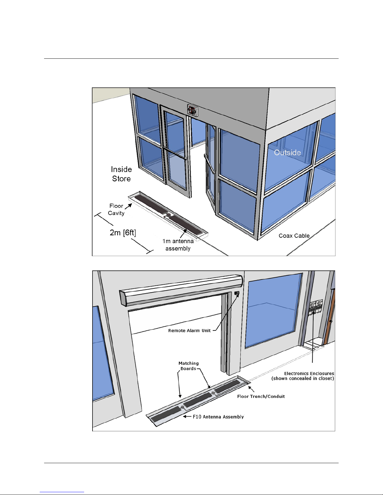
Many retailers are now requiring invisible EAS Systems. The F10 system is Checkpoint’s latest
invisible EAS offering. This product features a unique shielded antenna design based on the
previously released, S10 product. This technology minimizes the impact of in floor noise sources
that plagued previous floor systems.
Offering better immunity to noise, Next Gen Liberty (NGL) TR4215 Electronics are utilized for
F10 systems. It is anticipated that the next generation of Evolve electronics will eventually
replace the NGL electronics for the F10 system; thus the name “Evolve F10.” At this time, this
installation manual reflects installation and tuning for the NGL electronics only.
This manual instructs in the planning, installation and configuration of the EVOLVE F10 System.
Figure 1.1F10 System Introduction (F10, 2 meter installation shown)

F10 Installation Manual Rev. *60 10 of 71
Overview
This chapter explains F10 system hardware. This general information is useful for initial planning
and training purposes.
1. Hardware: Shows hardware components including the antenna assembly and electronics.
2. System Diagrams: Shows overall design and component layout of the F10 system.
F10 System Hardware
The F10 system is designed to be installed in the floor and provide an invisible EAS system. The
basic design is a 1 meter antenna assembly. Each antenna features multiple shielded coils. A
single assembly or two (2) units can be connected to a single Impedance Matching Board.
Figure 1.2F10 Hardware
Figure 1.3 TR4215 Electronics Enclosure
The F10 system consists of a transceiver-based system using pulse/listen technology, allowing
them to work in a single antenna configuration. In the same way that the NLG FX2012 system
works, F10 antennas connect to a remote electronics enclosure via a coax cable.
The antenna is wired directly to an Impedance Matching Board, another component that is
installed in the floor (i.e. buried along with the antenna). The Impedance Matching Board
provides the link between the antenna wiring and coax cable that connects to the remotely
located electronics enclosure. Typical EAS peripherals are able to be incorporated.
The electronics enclosure is designed to ensure proper ventilation in a non-condensing 0-40O C
environment. The wiring for the electronics system is a low-voltage, limited-energy system
(operating at 24VDC or less). All wiring must conform to applicable wiring codes.
The F10, 2 meter kit includes one (1) Impedance Matching Board for connecting the two (2)
antennas to a single Electronics Enclosure via two (2) coax cables routed through a single piece of
conduit. The power supply unit (not shown) is the standard +24VDC unit (refer to Appendix A:
Power Supply).
F10 Installation Manual Rev. *60 11 of 71
System Diagrams
The F10 system uses an antenna assembly comprised of wire coils wrapped around ferrite material
tiles. Antennas areenclosed in PVCcasings for strength and protection from environmental factors.
Figures 1.4 and 1.5 show commoninstallation coverage widths: 2m and 3m [6 and 9ft respectively].
Figure 1.4 Typical F10, 2 Meter Installation
Figure 1.5 3m [9ft] Installation Layout with Component Names
F10 Installation Manual Rev. *60 12 of 71
Grouping Multiple Antennas
Larger aisles are able to be covered using a Sync configuration. Aisle widths of any 1m increment
are possible. The 3m configuration features an F10, 2 meter system and a single 1 meter system.
Similarly, the 5m layout features two (2) F10, 2 meter systems and the standard F10 antenna.
Multiple electronics enclosures and power supplies are required, in this case, and the system
electronics must be configured for operation as a single unit. Refer to the “Wiring Between
Systems for Sync” section.
Multiple floor trenches are cut with each length of ENT tubing (conduit) spaced 5.1 cm [2in] from
the next closest to reduce RF interference.
Although grouping multiple installation kits together is possible, it requires approval from
Checkpoint’s Product Management. Feasibility is confirmed during the initial planning stage
known as the “Site Survey.” If the Site Survey was already performed and at present you are
prepared with installation-specific details, please skip to Chapter 3: Physical Installation.
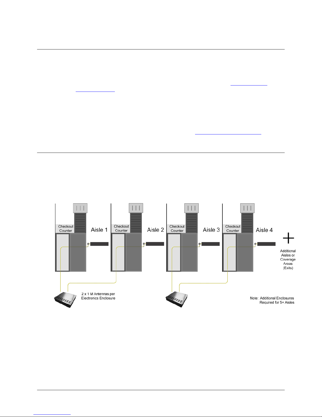
2 x 1 Meter Configuration
When necessary, two (2) standard F10, 1meter systems are connected to the same electronics
enclosure in a 2 x 1 meter configuration. The common application of the F10, 2 x 1 meter
configuration is in a grocery store or large department store. This setup allows EAS coverage
of many store checkout aisles, as well as single-door entrance / exit layouts. Each 1m antenna
assembly is fitted with a Matching Board. The layout minimizes the total number of electronics
enclosures needed when multiple F10 systems are used.
Figure 1.6 F10, 2 x 1 Meter System Diagram

F10 Installation Manual Rev. *60 13 of 71
CHAPTER
2
SITE SURVEY
Overview
Checkpoint Field Service personnel visit the location to perform a site survey before installation.
The initial planning stage is the appropriate time to determine site suitability, where the antenna
loops will be located (for maximum EAS protection) and the type of systems to be installed.
Antenna Distance from Interfering Elements
Nearby elements and underlying flooring materials may cause interfering effects. Therefore,
antenna placement must be carefully evaluated before installation. Your goal is to identify a
location where ambient noise and environmental factors do not degrade system performance.
For repeatability, all measurements are given at baseline (i.e. using a standard tag type).
Figure 2.1 Distances from Interfering Elements

F10 Installation Manual Rev. *60 14 of 71
Common interfering elements and their minimum distances from F10 Antennas are listed below:
Expansion Joints: The minimum distance from an expansion joint is 0.6 m [2 ft].
Vertical Cabling: The minimum distance from vertical cabling is 2.4 m [8 ft].
Metal Wall Studs: The minimum distance from a metal wall stud is 0.9 m [3 ft].
Sliding Doors (Metal): The minimum distance from a metal sliding door is 1.2 m [4 ft].
Tagged Merchandise: The minimum distance from tagged merchandise is 1.8 m [6 ft].
Inward and Outward Swinging Doors (Metal): The minimum distance from either a
manual- or automatic-swinging metal door frame is 0.6 m [2 ft].
Although this last type of door is not shown in the figure, the fact that swinging metal doors can
swing toward the antenna loop must be taken into account (see below).
Note: The antenna must notbe located below the door (or too near the door) when fully opened. Locate the
F10 antenna components beyond the door – with a minimum clearance gap of 0.6m [24in].
Other Checkpoint equipment could interfere with the F10 system or vice se versa (refer
to Appendix C: Interactions for recommended separation distances).
System Performance Considerations
Nearby wiring and lighting, as well as floor construction, may affect performance. With RF
interference that is too severe and cannot be alleviated, the site may not be suitable for any
installations.
The detection field is not uniform (refer to Appendix D: Detection Performance for diagrams).
Each of the following alters F10 system performance:
•Spacing between the antenna and steel deck in the floor can affect performance, but it
has been observed that an increase in detection can occur when the F10 system is placed
on any metal flooring.
•Floor structuremay cause detection variation for the F10 system.
•Antenna configuration will cause an expected (known) change in detection heights and
a unique coverage pattern. Refer to Appendix D: Detection Performance for detail.
•Signal strength- The plots in the appendix have a defined height at TX = 31 (the
maximum). If TX is less than 31, detection heights will decrease.
Determining the Electronics Location
During the site survey, evaluate the store’s layout to learn what options are available for locating
the electronics enclosure and power supply. The electronics and power supply may be placed close
together, although this is not required. Both units may be placed under a cashwrap counter, under
shelving, above a drop ceiling (see special requirements), or in a utility closet.
The updated power supply can be installed in the plenum (i.e., above a drop ceiling or in HVAC
areas), but this requires a conversion kit (refer to Appendix A: Power Supplyfor complete details).
If necessary, the electronics enclosure can be located in the plenum – and as long as the power
supply is located outside of the plenum – no conversion kit is required.
Note:Since the “Hood Kit” (CKP P/N: 7367100) must beordered separately, determine whether or not one
is needed now.
Caution: If using the conversion kit, the power supply must be installed bya licensed electrician.

F10 Installation Manual Rev. *60 15 of 71
Electronics Enclosure Placement Requirements
•Locate the electronics enclosure no further than 12.2m (40 linear-feet) or 15.2m
(50 cable-feet) from the antenna(s) to allow for bends in the conduit run.
•If wall-mounting is ideal, mount the electronics enclosure approximately 1.8m [6ft]
above the floor to reduce RF-interaction with wiring in either the ceiling or the floor.
Electronics mounted to the ceiling can potentially have a high RF-interaction with the surrounding
environment (e.g., metal rafters or power cables), and therefore, may not perform optimally here.
Observe locations of active noise sources including deactivators.
Environmental Considerations
F10 systems are only approved for indoor installations only. For a first floor (ground level)
installation where the slab will be on grade (i.e., directly above the natural ground), we
recommend the concrete be poured above a vapor barrier to prevent moisture from rising.
The store's architect will recommend the maximum permissible loading in the floor area where
F10 antennas are physically installed. The architect must consider such factors as anticipated
traffic over the floor and the material characteristics of the flooring (if covered by concrete).
The guidelines included in this guide assume installation into concrete (typical), but the antennas
may be placed directly on concrete if flooring, such as finished hardwood, laminate, tile or stone,
conceals the system below. If a wooden floor is placed on top of the system, the weight of the
floor should not rest on the antenna(s). Moreover, with all installations, the concrete and other
materials above the antenna(s) cannot be metallic. For example, wire mesh cannot be used for
reinforcement above the concrete. Metallic walk-off mats should not be placed above the system.
Note: Tile grout and mortar used to fill antenna trenches MUST BE non-metallic and non-magnetic grout.
Another environmental consideration is a metal security gate. For installations where the drop
down or sliding gate could cause a phantom alarming issue, a Badge Board II (CKP P/N 7528451)
and a Gate Inhibit Switch (CKP P/N 7140188) should be installed. Discuss with Product
Management and customers.
As for the electronics, typical indoor conditions must be met. Operating temperature is 0°C to
+40°C [32° to 104°F]. Permissible humidity range is 10 to 75%.
Site Survey Conclusion
Overall, the site survey is an opportunity to gather details and share information required for the
proper installation workflow. Before leaving the test site, the location of the electronics enclosure,
floor cuts (trenches or “channels”), and/or conduit runs (see note) should be documented.
Using the information in the following chapter, draw up a plan with exact dimensions. In addition
to floor cuts, the power outlet locations (or hardwire into electrical for plenum installation) should
be planned. Coordinating with site contractors facilitates easier installation.
Note: For the F10 System, it is required that the coax cable is ranthrough ENT Tubing (conduit).
Communicate with the contractor (and/or store personnel) before concrete has been poured. This
crucial action will allowthe coax cable to be easily routed through the conduit.
Caution: Ensure wirerun does not exceed themaximum distance to the electronics’ planned location.

F10 Installation Manual Rev. *60 16 of 71
CHAPTER
3
PHYSICAL INSTALLATION
Chapter Outline
This chapter offers diagrams and lists steps for physical installation of the major system hardware:
1. Requirements: Lists the tool and part requirements for a typical installation.
2. Installation Outline: Lists all of the basic installation steps as a sequence.
3. Cut Diagrams: How to plan/make cuts for proper installation of the antenna assembly,
Impedance matching board, and plan/route the wiring of the coax cable.
4. Mounting the Electronics:How to install the electronics enclosure and power supply.
Requirements
Tools
The following tools may be required for F10 system installations:
Arrow T-25 Staple Gun
Diagonal wire cutter
Hammer drill with 3/16” and 1/2” bits
Extension cord
Tape Measure
Hammer
Marker, Black Felt
Ratchet driver with 9/16” socket
Screwdrivers: mini, regular and #2 Phillips
Hacksaw
Utility knife
Wire Snake
Wire Strippers
Wrench, combination end 9/16”
Checkpoint Systems Field Service Diagnostic Management Software (DMS version
1.8.31 or later version) installed on a laptop with the appropriate cables.

F10 Installation Manual Rev. *60 17 of 71
Parts
Quantity will vary according to system type.
18 AWG 2-conductor (STP) Power
22 AWG 4-conductor (STP) (5594) Sync
PVC cement
*DekDuct (wire chase)
*Wiremold (1500 or 2600 series)
*Wiremold anchor bolts
Note: *Wire routing methods will vary by installation.
Note: Complete parts lists with OEM Part Numbers are included in Appendix B: Part Lists.
Installation Outline
Follow this sequence to successfully install the components and validate system operation:
1. Determine optimal antenna placement:
a. Perform a site survey now, or
b. Use the results of a previous survey.
2. Determine power supply requirements and the ideal location for system electronics.
3. Physically install the antenna(s).
4. Route/connect the antenna (coax cable) and applicable wiring (sync, alarm, power).
5. Install the peripherals and wire the device(s) to the electronics enclosure.
6. Configure the system using DMS.
7. Perform system specific tuning (test jump positions).
Antenna Installation
Antenna installation and tuning is performed by trained Checkpoint personnel. You have already
determined the system model(s) and number of assemblies for install, or you recently received this
key information from a prior survey. If you are unsure of any specifics, contact Checkpoint Project
Management. Install the antenna(s) in the proper location(s) discovered during the site survey.
During Construction
If the floor has not been poured yet, a pre-fabricated trough can be constructed. Refer to Figures
3.3 and 3.4. In the event of a new construction, please convey the following information to the site
contractors (construction team’s foreman) or the manager responsible for pouring the concrete:
•Location where antenna (s) will be placed; define a reference point (such as a door frame).
•The exact dimensions of antenna(s); provide the appropriate Floor Cut diagram(s).
•The depth, length and pathway of the 1/2” ENT Tubing (conduit), if installed ahead of
time; depth of the trench for routing the cable is 3.8cm [1.5in] deep.
After Construction
For sites where floor cuts must be made, convey the following instructions to the installing
technician. Communicate all known specifics to the installer, referring to the diagram(s). Be sure
to convey plans and instructions for the correct system type. Only provide the floor layout(s) for
required antenna configuration(s). If using a chisel, rough / uneven floor cuts may occur. Flatten
the bottom surface on which the antenna rests with either leveling sand or a layer of concrete fill.
F10 Installation Manual Rev. *60 18 of 71
Caution: Prevent uneven stress on the fragile electronic components inside the assembly by ensuring the
floor trough is smooth and level. Fill in uneven areas or gaps with leveling sand or concrete filler.
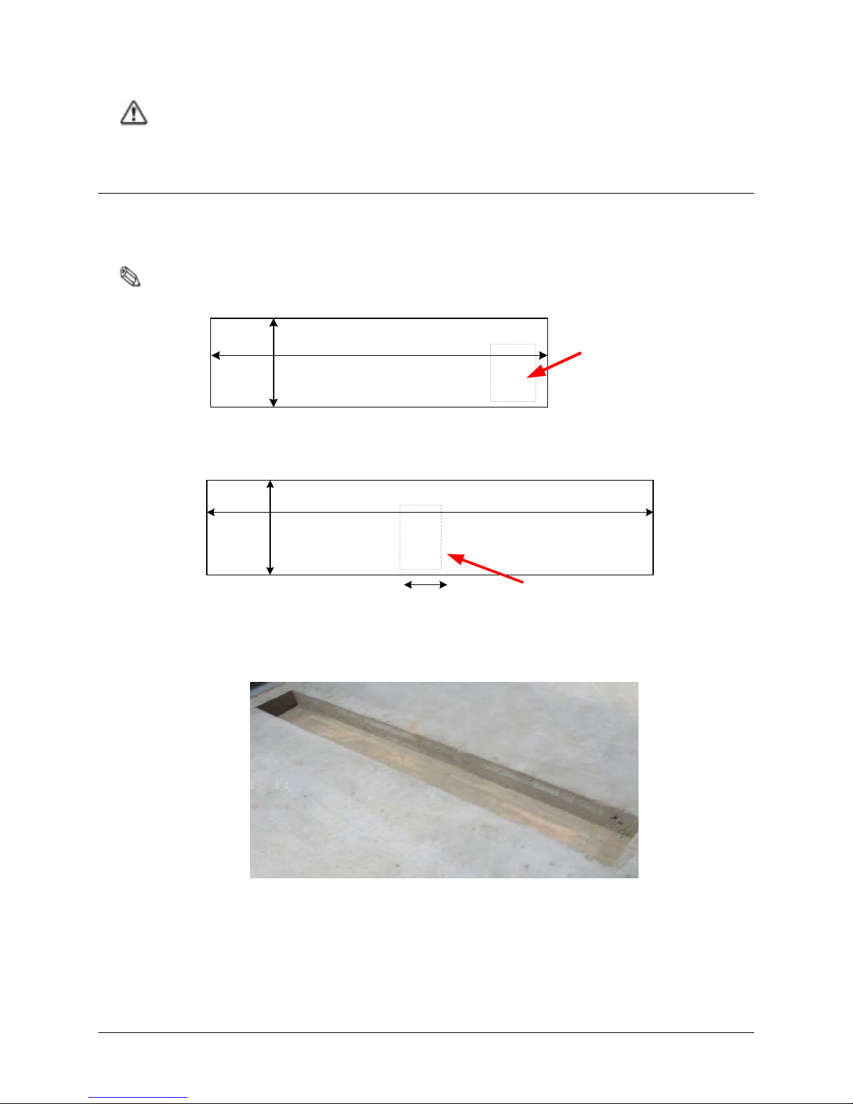
F10, 1 Meter and 2 Meter Floor Cuts
Installing the F10 antenna assembly in an existing store requires a trough to be cut in the floor.
If the site is under construction, it is easier to mold the system into the floor (explained above).
These diagrams include details on the size of the trough cuts required for each configuration.
Note: Figures are Not Drawnto Scale
127.6cm [50.25in]
35.5cm
[14in]
F10 Matching
Board Location
Figure 3.1 Top View of F10, 1 Meter Floor Cut
F10 Matching
Board Location
21.8cm [8.6in]
234.5cm [92.33in]
35.5cm
[14in]
Figure 3.2 Top View of F10, 2 Meter Floor Cut
Figure 3.3Trough for the 2 Meter assembly
F10 Installation Manual Rev. *60 19 of 71
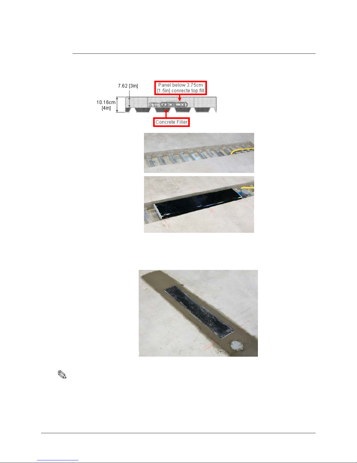
Floor Cut Depth
F10, 1 meter and 2 meter Antennas are identical, so the trough’s floor cut depth (height) is always
consistent. Recommended depth is 7.6cm [3in] for optimum structural integrity. This allows
approximately 3.75cm [1.5in] of concrete top fill covering each antenna (as shown in Figure 3.3).
Figure 3.3 Side View of Trough
Figure 3.4 Antenna Installed (not buried until after testing)
In scenarios where the flooring does NOT physically allow such depth, it is acceptable to cover
the antenna assembly with less than 1.5 inches of concrete fill. Although it is uncommon, when
covering with tile or wood flooring, the system can be installed flush to the concrete’s surface.
Figure 3.5 Flush Depth
Note: If installing in a location that violates the recommended 7.6cm [3in] depth specification, inform
Checkpoint Project Management.

F10 Installation Manual Rev. *60 20 of 71
Common Wider Floor Cuts
It is possible to create a wider system by combing either of the smaller two floor kits (refer to
Figures 3.1 and 3.2 above). For example, to cover a 3m mall opening, a 1m and 2m kit are ordered.
Figure 3.6 below shows exact dimensions of the trough (floor cuts) when the F10, 1 meter and 2
meter systems are combined. Figure 3.7 shows two (2) F10, 2 meter systems installed side-by-side.
354.5cm [139.6in]
Matching Board
Locations
117.5cm
[46.27in]
224.2cm [88.3in]
35.5cm
[14in]
21.8cm
[8.6in]
Figure 3.62m and 1m System for 3m Opening
Note: Figures are Not Drawnto Scale
461cm [181.5in]
Matching Board
Locations
35.5cm
[14in]
117.5cm
[46.27in] 117.5cm
[46.27in]
Figure 3.7Side-by-Side 2m Systems for 4m Opening
Note:The Impedance Matching Board placement for the F10, 2 meter system is between the assemblies.
For the F10, 1 meter system, board placement is beside the antenna assembly. The ENT Tubing
(with coax cable) can be routed in any direction from antenna to electronics. A minimum spacing of 2”
between theantenna andtubing is required.
Table of contents
Other Checkpoint Antenna manuals


