TBB power Solar Max CPI Series User manual

CPI User Manual V1.2
TBB Power Co.,Ltd
Solar Max CPI series
Off-grid Inverter
USER MANUAL
Version 1.2
Date: Nov. 2013

CPI User Manual V1.2
TBB Power Co.,Ltd
1
A
Ab
bo
ou
ut
t
T
TB
BB
B
TBB Power is a dedicated designer and manufacturer of sophisticated and environmentally
rugged power electronics equipment.
We are offering a wide range of power conversion product from battery charger, standalone
inverter, inverter charger combination and solar charge controller.
We ensure consistent product quality by subjecting every product to strictly choice of superior
quality components, rigorous testing and burn-in through out the production process. TBB
Power is certified by TUV in accordance with ISO9001 and can be your reliable power solution
provider.
D
Di
is
sc
cl
la
ai
im
me
er
r
Unless specially agreed in writing, TBB Power Co.,Ltd
Take no warranty as to the accuracy, sufficiency of suitability of any technical or other
information provided in this manual or other documentation.
Assumes no responsibility or liability for loss or damage, whether direct, indirect,
consequential or incidental, which might arise out of the use of such information
A
Ab
bo
ou
ut
t
t
th
hi
is
s
M
Ma
an
nu
ua
al
l
This manual describes our product features and provides procedure of installations. This manual is
for anyone intending to install our equipment.
C
Co
on
nt
ta
ac
ct
t
I
In
nf
fo
or
rm
ma
at
ti
io
on
n
TBB Power Co.,Ltd
Web: www.tbbpower.com
Tel: +86-592-5212299
Fax: +86-592-5796070
Email: service@tbbpower.com

CPI User Manual V1.2
TBB Power Co.,Ltd
2
G
Ge
en
ne
er
ra
al
l
I
In
ns
st
tr
ru
uc
ct
ti
io
on
n
Thanks for choosing our products and this manual were suitable for CPI series pure sine wave
inverter.
This chapter contains important safety and operation instructions. Read and keep this User
Guide well for later reference.
The CPI series needs to be installed by professionals and please pay attention to the following
points prior to installation:
1> Please check the input voltage or voltage of battery is same to the nominal input voltage of
this inverter.
2> Please connect positive terminal “+” of battery to “+” input of the inverter.
3> Please connect negative terminal “-” of battery to “-” input of the inverter.
4> Please use the shortest cable to connect and ensure the secure connection.
5> While connecting, please secure the connection and avoid short cut between positive
terminal and negative terminal of battery, which will cause damage of battery.
6> Inverter will have high voltage inside. Only authorized electrician can open the case.
7> The inverter WAS NOT designed to use in any life retaining equipment.

CPI User Manual V1.2
TBB Power Co.,Ltd
3
I
In
nd
de
ex
x
1.0 General Safety Instruction
1.1 Safety Instruction
1.2 General Precaution
1.3 Precaution regarding battery operation
2.0 Description
3.0 Structure
4.0 Setting
4.1 Low Voltage disconnect (LVD)
4.2 Output Voltage and Frequency
5.0 Control and Communication
5.1 Dry contact
5.2 RCC
6.0 Installation
6.1 Material List
6.2 Location
6.3 Wiring recommendation
6.4 General Advice
6.5 Installation and Connection
7.0 Operation
8.0 Trouble Shooting
9.0 Specification

CPI User Manual V1.2
TBB Power Co.,Ltd
4
1
1.
.
G
Ge
en
ne
er
ra
al
l
S
Sa
af
fe
et
ty
y
I
In
ns
st
tr
ru
uc
ct
ti
io
on
n
1
1.
.1
1
S
Sa
af
fe
et
ty
y
I
In
ns
st
tr
ru
uc
ct
ti
io
on
n
As dangerous voltages and high temperature exist within the CPI, only qualified and authorized
maintenance personnel are permitted to open and repair it.
This manual contains information concerning the installation and operation of the CPI. All
relevant parts of the manual should be read prior to commencing the installation. Please follow
the local stipulation meantime.
Any operation against safety requirement or against design, manufacture, safety standard, and
are out of the manufacturer warranty.
1
1.
.2
2
G
Ge
en
ne
er
ra
al
l
P
Pr
re
ec
ca
au
ut
ti
io
on
n
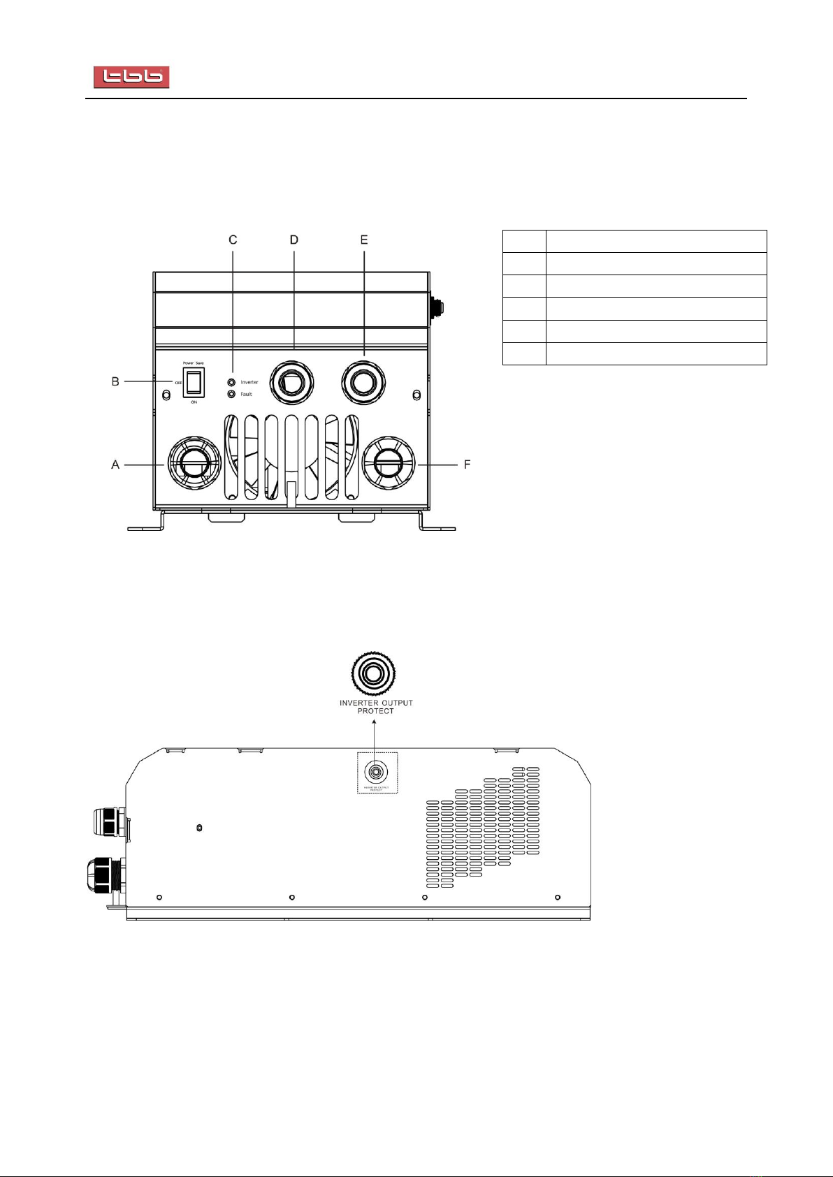
1.2.1 Do not expose to dust, rain, snow or liquids of any type,it is designed for indoor use. DO
NOT block off ventilation, otherwise the INVERTER would be overheating.
1.2.2 To avoid fire and electric shock,make sure all cables selected with right gauge and being
connected well. Smaller diameter and broken cable are not allowed to use.
1.2.3 Please do not put any inflammable goods near to inverter.
1.2.4 Never place unit directly above batteries, gases from a battery will corrode and damage
inverter/charger.
1.2.5 Do not place battery over inverter.
1
1.
.3
3
P
Pr
re
ec
ca
au
ut
ti
io
on
n
r
re
eg
ga
ar
rd
di
in
ng
g
b
ba
at
tt
te
er
ry
y
o
op
pe
er
ra
at
ti
io
on
n
1.3.1. Use plenty of fresh water to clean in case battery acid contacts skin, clothing, or eyes and
consult with doctor as soon as possible.
1.3.2. The battery may generate flammable gas during charging. NEVER smoke or allow a
spark or flame in vicinity of a battery。
1.3.3. Do not put the metal tool on the battery, spark and short circuit might lead to explosion.
1.3.4. REMOVE all personal metal items such as rings, bracelets, necklaces, and watches while
working with batteries. Batteries can cause short-circuit current high enough to make
metal melt, and could cause severe burns.

CPI User Manual V1.2
TBB Power Co.,Ltd
5
2
2.
.0
0
D
De
es
sc
cr
ri
ip
pt
ti
io
on
n
CPI is a pure sine wave inverter specially designed for solar off grid application, of which could
deliver high quality power with unexpected overload capability.
Pure Sine Wave
Outstanding Peak Power
High efficiency up to max 94%
Extremely low status consumption power
Power save mode available
Low voltage disconnect level settable
High temperature design
Built in auxiliary contact for battery low alarm
Comprehensive Protection
Remote control available

CPI User Manual V1.2
TBB Power Co.,Ltd
6
3
3.
.0
0
S
St
tr
ru
uc
ct
tu
ur
re
e
F
Fr
ro
on
nt
t
P
Pa
an
ne
el
l
A
DC cable through hole
B
Main switch
C
LED
D
Gland for remote control cable
E
Gland for AC output
F
DC cable through hole
S
Si
id
de
e
P
Pa
an
ne
el
l
On Right side panel, there is a circuit breaker as a overload protection for inverter output.

CPI User Manual V1.2
TBB Power Co.,Ltd
7
C
Ce
en
nt
tr
ra
al
l
P
Pa
an
ne
el
l
A
Dry contact (battery low)
B
Dip Switch
C
RCC panel connector
D
E
AC output terminal
F
DC -
G
DC +

CPI User Manual V1.2
TBB Power Co.,Ltd
8
4
4.
.0
0
C
Co
on
nf
fi
ig
gu
ur
ra
at
ti
io
on
n
Through dipswitch at central panel, you can have some
configuration of the inverter
4
4.
.1
1
L
Lo
ow
w
V
Vo
ol
lt
ta
ag
ge
e
d
di
is
sc
co
on
nn
ne
ec
ct
t
(
(L
LV
VD
D)
)
Through the Dip Switch 1, you can configure the low voltage protection level for your system.
Please find following data.
The following DOD is estimation ONLY. The exact measure of the battery SOC is almost
impossible with only electrical parameter. It may vary according to discharge current, battery
healthy etc.
SW1
1
12
2V
VD
DC
C
m
mo
od
de
el
l
2
24
4V
VD
DC
C
m
mo
od
de
el
l
4
48
8V
VD
DC
C
m
mo
od
de
el
l
e
es
st
t
D
DO
OD
D
r
re
ec
co
om
mm
me
en
nd
da
at
ti
io
on
n
off
11.7VDC
23.4VDC
46.8VDC
ab. 60%
solar or backup
on
10.5VDC
21VDC
42VDC
>90%
mobile
The default setting was OFF, 11.7VDC (12V model) / 23.4VDC (24V model) / 46.8VDC (48V
model)

CPI User Manual V1.2
TBB Power Co.,Ltd
9
4
4.
.2
2
O
Ou
ut
tp
pu
ut
t
V
Vo
ol
lt
ta
ag
ge
e
a
an
nd
d
F
Fr
re
eq
qu
ue
en
nc
cy
y
C
Co
on
nf
fi
ig
gu
ur
ra
at
ti
io
on
n
Through the Dip Switch 2 and 3, you can configure the output with various voltages for high
voltage model (HV model) and low voltage model (LV model).
D
Di
ip
p
S
Sw
wi
it
tc
ch
h
2
2
D
Di
ip
p
S
Sw
wi
it
tc
ch
h
3
3
O
Ou
ut
tp
pu
ut
t
v
vo
ol
lt
ta
ag
ge
e
o
of
f
H
HV
V
M
MO
OD
DE
EL
L
O
Ou
ut
tp
pu
ut
t
v
vo
ol
lt
ta
ag
ge
e
o
of
f
L
LV
V
M
MO
OD
DE
EL
L
OFF
OFF
230VAC
110VAC
ON
OFF
208VAC
100VAC
OFF
ON
240VAC
127VAC
ON
ON
220VAC
120VAC
Through the Dip Switch 4, you can configure the output frequency.
S
SW
W4
4
H
HV
V
m
mo
od
de
e
L
LV
V
m
mo
od
de
e
off
50HZ
60HZ
on
60HZ
50HZ
N
No
ot
ti
ic
ce
e
Dip switch 5 was preserved without any function at present.

CPI User Manual V1.2
TBB Power Co.,Ltd
10
5
5.
.0
0
C
Co
on
nt
tr
ro
ol
l
a
an
nd
d
C
Co
om
mm
mu
un
ni
ic
ca
at
ti
io
on
n
5
5.
.1
1
D
Dr
ry
y
c
co
on
nt
ta
ac
ct
t
CPI has a built in dry contact. It will activate as soon as the battery voltage
was detected dropping to threshold level which is 0.5VDC above the LVD
level
The maximum contact load is:
230Vac /110Vac : 2A
12Vdc/24Vdc/48Vdc : 2A
5
5.
.2
2
R
RC
CC
C
-
-
R
Re
em
mo
ot
te
e
C
Co
on
nt
tr
ro
ol
l
(
(o
op
pt
ti
io
on
na
al
l)
)
Optional RCC –remote control could be purchased and connected to the CPI on central panel to
have following functions:
Load percentage
Battery SOC: battery LED, from bottom to top representing 25%-50%-75%-100%
Working status
Alarm info
Main switch: set your equipment at ON / OFF / PS mode

CPI User Manual V1.2
TBB Power Co.,Ltd
11
6
6.
.0
0
I
In
ns
st
ta
al
ll
la
at
ti
io
on
n
6
6.
.1
1
M
Ma
at
te
er
ri
ia
al
l
l
li
is
st
t
The unit is packed with following materials. Please confirm the series number on inverter is
same to that on outer carton
Equipment
User’s manual
a Remote module (optional)
6
6.
.2
2
L
Lo
oc
ca
at
ti
io
on
n
Please install the equipment in a location of Dry, Clean, Cool with good ventilation.
Working temperature :-10℃-50℃
Storage temperature :-40-70℃
Relative Humidity :0%-95%,non-condensing
Cooling :Forced air
6
6.
.3
3
W
Wi
ir
ri
in
ng
g
r
re
ec
co
om
mm
me
en
nd
da
at
ti
io
on
n
Please find the following minimum wire size. In case of DC cable longer than 1m, please
increase the cross section of cable to reduce the loss.
System capacity
AC wiring
DC wiring
110VAC
220VAC
48VDC
24VDC
12VDC
600W
2.5mm²
2.5mm²
4mm²
10mm²
16mm²
1KW
4mm²
2.5mm²
6mm²
16mm²
25mm²
1.5KW
4mm²
2.5mm²
10mm²
25mm²
35mm²
2KW
6mm²
2.5mm²
16mm²
25mm²
50mm²
3KW
8mm²
4mm²
25mm²
50mm²
70mm²
4KW
10mm²
4mm²
25mm²
50mm²
\
5KW
16mm²
6mm²
35mm²
70mm²
\
6KW
16mm²
6mm²
50mm²
\
\

CPI User Manual V1.2
TBB Power Co.,Ltd
12
6
6.
.4
4
G
Ge
en
ne
er
ra
al
l
a
ad
dv
vi
ic
ce
e
Ensure that the inverter has the correct DC voltage with your existing battery system
Install the CPI as close to the batteries as possible reducing the voltage drop on cable for the
better performance of the equipment.
Do not connect the output of this equipment to your AC system at the same time as
any other AC source such as the 230V external mains or a generator.
We recommend connecting a DC fuse corresponding to the conductor between battery and
CPI, which will offer protection to the battery cable.
On the AC output side, we recommend connecting the output from the inverter to a suitable
Residual Current Circuit Breaker and Circuit Breaker.
6
6.
.5
5
I
In
ns
st
ta
al
ll
la
at
ti
io
on
n
a
an
nd
d
C
Co
on
nn
ne
ec
ct
ti
io
on
n
For the user operation safety, cut off the power before installation
6
6.
.5
5.
.1
1
F
Fi
ix
x
t
th
he
e
e
eq
qu
ui
ip
pm
me
en
nt
t
Basically, CPI could be installed either vertically on wall or horizontally on floor
Please choose a flat surface and with 4XM6 to fix the unit securely
Please find following installation dimension.
492
460
135
193
228
30080 ?12
205
?7
64 32 268 32
Frame A, for unit up to 1200W

CPI User Manual V1.2
TBB Power Co.,Ltd
13
Frame B, for unit up to 3000W
Power Save
ON
OFF Inverter
Fault
INVERTER OUTPUT
PROTECT
Frame C, for unit up to 6000W

CPI User Manual V1.2
TBB Power Co.,Ltd
14
6
6.
.5
5.
.2
2
C
Co
on
nn
ne
ec
ct
ti
in
ng
g
t
th
he
e
c
ca
ab
bl
le
e
Please make sure the CPI is turned off before connection. Otherwise, high
voltage could be present.
Loose the screw and remove the top panel
(if necessary) There is cable connecting the
LED/switch of front panel to equipment, please plug
out the connector at front panel. Then, loose the screw
and remove the front panel
Connecting DC cable of service battery
Please double check battery voltage match the model you are going to
installed, the wrong battery could destroy equipment and is out of warranty.
Please double confirm the polarity of DC input. Reverse polarity could cause
permanent damage on equipment and it is out of warranty.
Choose the right cable size (refer to 6.3) and follow polarity guide marked on the panel
Pull through the DC cables through the holes at front panel, clamping the cable terminal on
cable.
Secure the battery cable on DC+ and DC- terminals respectively making sure it is tightly
screwed
Connecting the AC cable
AC output cable: choose the right cable size (refer to 6.3), pull through the AC output cable
through Gland and connect it on AC output block. Connectors are marked as “L”-line,
“N”-neutral and “PE”-earth. Making sure it is tightly screwed.
Please double check AC output was right after connection.
Wrong connection will cause permanent damage of equipment and it is out
of warranty.
The neutral output of CPI is connected to earth once switch on.

CPI User Manual V1.2
TBB Power Co.,Ltd
15
Connecting the earth
At the front bottom of base, there is an earth connection point.
Please connect it with EARTH by a proper gauge wire. (same wire gauge as you used connecting
the AC output earth/PE
6
6.
.5
5.
.3
3
I
In
ns
st
ta
al
ll
l
t
th
he
e
R
RC
CC
C
-
-
r
re
em
mo
ot
te
e
c
co
on
nt
tr
ro
ol
ll
le
er
r
The RCC was dash mounting design and can be hanged on wall too.
For dash mounting, please cut the hole according to following size and screw the remote controller
securely through four screws at corners and connected the cables.
Using the two cables supplied connecting the RCC to the port
on the central panel. Please refer to left picture.
RCC1 is a 6pin port and RCC2 is a 4pin port
Pull through the cable through Gland and secure the
installation afterwards.

CPI User Manual V1.2
TBB Power Co.,Ltd
16
7
7.
.0
0
O
Op
pe
er
ra
at
ti
io
on
n
7
7.
.1
1
D
Do
ou
ub
bl
le
e
C
Ch
he
ec
ck
ki
in
ng
g
Check the DC input voltage of this inverter is same to your battery nominal voltage. NEVER
try to connect different DC input to inverter.
Inspect if you connect right polarity of DC with battery
Inspect AC output connection is correct; make sure unit is no short cut.
7
7.
.2
2
S
Sw
wi
it
tc
ch
h
o
on
n
t
th
he
e
i
in
nv
ve
er
rt
te
er
r
Switching on the unit, the LED will all illuminate for analysis then there should be AC
available at inverter output. The inverter LED will illuminate. You could switch on the load
which will be powered by inverter.
The Load % LED will reflect the load level connected.
The SOC led will reflect the battery condition, which are 25%-50%-75%-100% respectively
from bottom.
For detail system info, you can read out from top panel and remote panel
T
To
op
p
p
pa
an
ne
el
l
R
Re
em
mo
ot
te
e
7
7.
.3
3
P
Po
ow
we
er
r
S
Sa
av
vi
in
ng
g
m
mo
od
de
e
You can set the CPI working in power save mode through the Main Switch either on inverter
front panel or through RCC remote panel. It is marked PS
Upon PS mode, Power Save mode LED on front panel will illuminate and the Inverter LED
on RCC remote panel will flash.
Under PS mode, the status consumption power can be dramatically reduced.

CPI User Manual V1.2
TBB Power Co.,Ltd
17
8
8.
.0
0
T
Tr
ro
ou
ub
bl
le
e
S
Sh
ho
oo
ot
ti
in
ng
g
√ : ON x : OFF
8.1 LED indicator and audible alarm on inverter
Status
Function
LED
Audible alarm
Inverter
Power
saving mode
Over load
Fault
Inverter
Inverter ON
√
×
×
×
×
Power Save mode
×
√
×
×
×
Alarm
Mode
Battery low voltage
√
×
×
√
beep 0.5s every 5s
Battery overvoltage
√
×
×
√
beep 0.5s every 1s
Inverter overload
√
×
√
√
beep 0.5s every 1s
Inverter overtemp
√
×
×
√
Beep 0.5s every 1s
Protection
mode
Fan block
×
×
×
×
beep continuously
Battery overvoltage
√
×
×
×
beep continuously
Battery low voltage
×
×
×
×
Inverter overload
×
×
√
×
beep continuously
overtemp
×
×
×
×
beep continuously
Shortcut
×
×
×
×
beep continuously
8.2 LED indicator on RCC remote panel
Status
Function
LED on remote panel
Inverter
Fault
Inverter
Inverter ON
√
×
Power Save mode
flash
×
Alarm Mode
Battery low voltage
√
√
Battery overvoltage
√
√
Inverter overload
√
√
Inverter overtemp
√
√
Protection mode
Fan block
×
×
Battery overvoltage
√
×
Battery low voltage
×
×
Inverter overload
×
×
overtemp
×
×
Shortcut
×
×
8.3 Percentage Bar on RCC remote panel
percentage bar
Load BAR
from bottom to top representing 25%-50%-75%-100% load percentage of inverter
SOC BAR
from bottom to top representing 25%-50%-75%-100% of battery SOC

CPI User Manual V1.2
TBB Power Co.,Ltd
18
9
9.
.0
0
S
Sp
pe
ec
ci
if
fi
ic
ca
at
ti
io
on
n
C
CP
PI
I
H
HV
V
m
mo
od
de
e
S
Sp
pe
ec
ci
if
fi
ic
ca
at
ti
io
on
n
Model No.
12Vdc
CPI1000L
CPI1200L
CPI1500L
CPI1800L
CPI2000L
24Vdc
CPI1000M
CPI1200M
CPI1500M
CPI1800M
CPI2000M
CPI3000M
48Vdc
CPI2000S
CPI3000S
CPI4000S
CPI5000S
CPI6000S
Electrical
Norminal Voltage
12Vdc, 24Vdc, 48Vdc
Cont output power
(40℃)
1000W
1200W
1500W
1800W
2000W
3000W
4000W
5000W
6000W
Cosφ
0.9-1
Overload
Capability
>150%
20s
>125%
60s
>110%
15mins
1min
Surge
300%
Output voltage
208/220/230/240VAC ± 2%
Output frequency
50/60Hz ± 0.1%
Efficiency
12Vdc
89%
24Vdc
92%
48Vdc
94%
Crest factor
.3:1
THD
<3%
Zero load power
12.5W
13W
14W
14.5W
15W
18W
26W
32W
36W
Zero load power
(power save mode)
3W
3.5W
3.5W
3.6W
3.75W
4.5W
6W
8W
9W
Output circuit breaker
10A
10A
10A
15A
15A
30A
30A
30A
30A
Overload and
overheat protection
auto disconnect with 3 times restart attempt
shortcut protection
auto disconnect
Other Data
Dry contact
Battery low
Battery connector
M8 x 2
Enclosure
Steel with powder paint
Dimension (mm)
460x228x135
487x228x180
487x396x180
Net Weight (kgs)
15
16
19
21
22
25
35
40
46
Cooling
Forced fan
Protection
IP21
Standard
Safety
EN60950-1
Emmission
EN55022
Immunity
EN55022

CPI User Manual V1.2
TBB Power Co.,Ltd
19
C
CP
PI
I
L
LV
V
m
mo
od
de
e
S
Sp
pe
ec
ci
if
fi
ic
ca
at
ti
io
on
n
Model No.
12Vdc
CPI1000L-LV
CPI1200L-LV
CPI1500L-LV
CPI1800L-LV
CPI2000L-LV
24Vdc
CPI1000M-LV
CPI1200M-LV
CPI1500M-LV
CPI1800M-LV
CPI2000M-LV
48Vdc
CPI2000S-LV
Electrical
Norminal Voltage
12Vdc, 24Vdc, 48Vdc
Cont output power at (40℃)
1000W
1200W
1500W
1800W
2000W
Cosφ
0.9-1
Overload
Capability
>150%
20s
>125%
60s
>110%
15mins
Surge
300%
Output voltage
100/110/120/127VAC ± 2%
Output frequency
50/60Hz ± 0.1%
Efficiency
12Vdc
89%
24Vdc
92%
48Vdc
94%
Crest factor
.3:1
THD
<3%
Zero load power
12.5W
13W
14W
14.5W
15W
Zero load power (power save
mode)
3W
3.5W
3.5W
3.6W
3.75W
Output circuit breaker
10A
10A
10A
15A
15A
Overload and overheat
protection
auto disconnect with 3 times restart attempt
shortcut protection
auto disconnect
Other Data
Dry contact
Battery low
Battery connector
M8 x 2
Enclosure
Steel with powder paint
Dimension (mm)
460x228x135
487x228x180
Net Weight (kgs)
15
16
19
21
22
Cooling
Forced fan
Protection
IP21
Standard
Safety
EN60950-1
Emmission
EN55022
Immunity
EN55022
This manual suits for next models
29
Other TBB power Inverter manuals
Popular Inverter manuals by other brands

Darfon
Darfon MIG300 installation manual

SMA Solar Technology AG
SMA Solar Technology AG SUNNY TRIPOWER 15000TL operating manual

Air Liquide
Air Liquide T 150i AC/DC owner's manual

Generac Power Systems
Generac Power Systems 8 KVA owner's manual

Carrier
Carrier TRANSICOLD 69UG15 Series Operation and service

GMTCNT
GMTCNT GMD Series instruction manual