Hayward Salt&Swim SAS-AU User manual

Salt & Swim
Chlorine Generator for
Swimming Pools up to 90,000 litres
TM
Owner’s Manual
Model: SAS-AU
Contents
Introduction....................1
Installation..................2-8
Operation.................12-14
Troubleshooting........... 15
Warranty........................21
Hayward Pool Products (Australia) Pty Ltd
Melbourne, Sydney, Brisbane, Perth
www.hayward-pool.com.au
092549 RevC
USE ONLY HAYWARD GENUINE REPLACEMENT PARTS

When installing and using this electrical equipment, basic safety
precautions should always be followed, including the following:
•READAND FOLLOWALL INSTRUC-
TIONS
• TOREDUCETHERISKOFDROWNINGFROMHAIRAND
BODYENTRAPMENT,INSTALLASUITABLYRATEDSUCTION
GUARDTOMATCHTHEMAXIMUMFLOWRATEMARKED.
• WARNING-Toreducetheriskofinjury,donotpermitchildren
to use this product unless they are closely supervised at all
times.
• WARNING–RiskofElectricShock.Connectonlytoapower
outlet protected by a Residual Current Device - RCD, with a
residual operating current of 30mAas perAS/NZS 3000Wiring
Rules.
WARNING–Toreducetheriskofelectricshock,havedamaged
cord(s) replaced immediately by the manufacture, its service
agentorsimilarlyqualiedpersons.
•WARNING–Toreducetheriskofelectricshock,installunitat
least3.5metreshorizontallyfromtheinsidewallsofapoolor
spa/hottubandataheightfromthegroundnotlessthan0.45
metresandinaccordancewithAS/NZS3000wiringrules.
•Do not bury cord. Locate cord to minimise abuse from lawn
mowers,hedgetrimmers,andotherequipment.Donotusean
extensioncordtoconnecttheunittothepoweroutlet.
•SAVETHESEINSTRUCTIONS
USE ONLY HAYWARD GENUINE REPLACEMENT PARTSUSE ONLY HAYWARD GENUINE REPLACEMENT PARTS

Introduction
The Salt & SwimTM is an automatic chlorine generation system for pool sanitisation. It is
designed for swimming pools up to 90,000 litres only. The Salt & Swim is not to be used
with above ground pools or with in-ground pools greater than 90,000 litres.
The unit provides a linecord for input power and a receptacle for the filter pump. The SAS-AU will
turn the pump on/off based on timer settings and produce chlorine only when the pump is running.
This SAS-AU model is designed for use with 40mm or 50mm pool plumbing and must be installed
by a qualified installer. The Cell Vessel must be glued into the pool's plumbing system.
The Salt & Swim requires a low concentration of salt (sodium chloride) in the pool water. It auto-
matically sanitises your pool by converting the salt into free chlorine which kills bacteria and algae
in the water. Chlorine will revert back to sodium chloride after killing bacteria. These reactions
will continuously recycle virtually eliminating the need to add sanitising chemicals to your pool.
The Salt & Swim can handle the purification needs of most residential swimming pools up to 90,000
litres. This unique low cost chlorine generator uses a replaceable electrolytic Cell (SAS-CELL)
that is designed to produce 90Kg of 100% available chlorine over its lifetime.
Note that the actual amount of chlorination required to properly sanitise a pool varies due to bather
load, rainfall, temperature, and the pool's cleanliness.
NOTE: Before installing this product as part of a saline water purification system in a pool or
spa using natural stone for coping or for immediately adjacent patios/decking, a qualified stone
installation specialist should be consulted regarding the appropriate type, installation, sealant (if
any) and maintenance of stone used around a saline pool with electronic chlorine generator in
your particular location and circumstances.
NOTE: The use of dry acid (sodium bisulfate) to adjust pool pH is discouraged especially in arid
regions where pool water is subject to excessive evaporation and is not commonly diluted with
fresh water. Dry acid can cause a buildup of by-products that can damage your chlorinator Cell.
USE ONLY HAYWARD GENUINE REPLACEMENT PARTS

Installation
Remove power to the pool filter pump before starting this installation. Installation must be performed
in accordance with local codes and AS/NZS 3000 Wiring Rules. The Control Box must be mounted a
minimum of 3.5m horizontal distance (or more, if local codes require) from the pool, within 2 metres
from a RCD protected outlet, and within 4.5 metres from where the Cell will be installed. Take care
to protect the Cell Cap connector pins while handling the Salt & Swim unit during installation. If the
supply cord is damaged, it must be replaced by the manufacturer, its service agent or similarly quali-
fied persons in order to avoid a hazard.
Preparing Pool Water
To prepare the pool water for Salt & Swim operation, the pool's chemistry must be balanced and salt
must be added. This must be done BEFORE activating the Salt & Swim. Some adjustments to your
pool chemistry may take several hours, so start the procedure well before you intend to operate the
Salt and Swim.
To prepare your pool water, follow the instructions on the included Pool Chemistry Quick Start Guide
and refer to page 8 of this manual.
Adding Salt: Add salt several hours or, if possible, 1 day prior to operating the Salt & Swim. Take
care not to exceed the recommended salt level. Measure salt 6-8 hours after adding to the pool.
NOTE: If the pool does not have new water, add 1 litre of metal remover and 1 litre of non-copper
based algaecide to the pool, per manufacturer's instructions. This ensures a quick, troublefree
transfer to the Salt & Swim system.
Salt & Swim Installation
Follow the step by step instructions located on the Installation Quick Start Guide. Refer to the following
sections for more detailed information.
RCD protected
2
USE ONLY HAYWARD GENUINE REPLACEMENT PARTS

Mounting the Salt & Swim Control Box
The Salt & Swim is contained in a raintight enclosure that is suitable for outdoor mounting. The Control
Box must be mounted a minimum of 3.5 metres horizontal distance (or more, if local codes require)
from the pool, within 2m from a RCD protected outlet, and within 4.5m from where the Cell is installed.
The Control Box is designed to mount vertically on a flat surface with the cables facing downward.
Because the enclosure also acts as a heat sink (disperses heat from inside the box), it is important not to
block the four sides of the Control Box. Do not mount Salt & Swim inside a panel or tightly enclosed area.
Before securing the Control Box to the intended location, make sure that the power cord will reach
the RCD protected outlet and that the Cell cable will reach the location where the Cell Vessel will be
installed. Refer to the diagram below.
Plumbing
The Cell Vessel is designed to install in 40mm or 50mm PVC pool plumbing only. The Cell Vessel
must be installed on a 350mm run of straight pipe at the end of the return piping just before the water
returns to the pool. All pool equipment should be upstream from the Cell Vessel. It must be located
within 4.5m of where the Control Box is mounted. Also, there must be enough clearance to insert and
remove the Cell from the Vessel after the Vessel is installed.
USE ONLY HAYWARD GENUINE REPLACEMENT PARTS
3
USE ONLY HAYWARD GENUINE REPLACEMENT PARTS USE ONLY HAYWARD GENUINE REPLACEMENT PARTS
3

A minimum 200mm opening must be cut in the pool's plumbing to accept the Cell Vessel for 50mm
plumbing or more if using the 40mm reducers to suit 40mm plumbing. With power removed to the
pump and water drained from the pool plumbing, cut the pipe at the desired location.
After gluing the Cell Unions on to the cut pipe, position the Vessel in a manner where the Cell can be
easily inserted and removed. Secure the Vessel by handtightening the Unions.
SOLAR
SYSTEM
FROM
POOL
TO
POOL
FILTER HEATER
FIL TER
PUMP
200 mm
4
USE ONLY HAYWARD GENUINE REPLACEMENT PARTS

Remove the foam protector from the Cell. Fully cover Cell pins with supplied grease. Verify that the
O-ring is attached to the Cell before inserting the Cell into the Cell Vessel as shown.
USE ONLY HAYWARD GENUINE REPLACEMENT PARTS
5

Connect and Fasten Cell Cap
Slip the Cell Cap through the Retaining Nut as shown below. Plug the Cell Cap into the Cell and
secure with the Retaining Nut. Run pump for 5 minutes and check for leaks.
Bonding
Pool bonding or "equipotential bonding" ensures that all pool components around the pool are at
the same electrical potential. If bonding is required at your location (see local codes and AS/NZS
3000 Wiring Rules), a bonding lug is provided at the bottom of the Salt & Swim enclosure. Run an
eight gauge (8 AWG) solid copper wire from the bonding lug to your pool's existing bonding loop.
Cell Cap Retaining Nut
to Pool Bonding loop
6
USE ONLY HAYWARD GENUINE REPLACEMENT PARTS

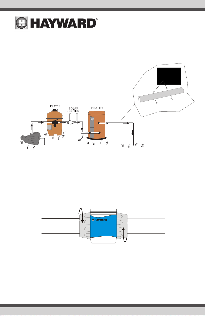
Filter Pump Connection
The filter pump plugs into the SASAU and is controlled based on schedule settings. Locate the
receptacle on the underside of the Salt & Swim enclosure. Note that the rating for this output is 240
VAC, 50hz, 9A. Ensure that your pump does not exceed the rating.
Flow Switch Calibration Procedure
IMPORTANT: Before going any further, the pool water must be balanced and salt must be added to
your pool. If this has not already been done, refer to "Water Chemistry" section of this manual for
information on how to prepare your pool water for Salt & Swim operation.
At start-up, or when a new Cell is installed, the Salt & Swim will run a Flow Switch Calibration
procedure to ensure that the Cell's flow switch is properly initialised. This will occur just once when a
new Cell is installed. After the flow switch is initialised, the Salt & Swim will not perform this
procedure again until the Cell is replaced. The Flow Switch Calibration procedure will require the
user to cycle the pump on and off. Follow the instructions below:
1. Plug the pump into the Salt & Swim.
2. Plug the Salt & Swim's linecord into a Residual Current Device (RCD) safety outlet or an outlet
protected by an RCD. Follow local and AS/NZS 3000 Wiring Rules.
After being powered on for the first time, the Salt & Swim will run a diagnostic routine which can
take up to 30 seconds. During this time, various LEDs will turn on and off. When finished, the
Salt & Swim will display a blinking LOW WATER FLOW LED and a solid GENERATOR RESTING
LED. Keep the Salt & Swim powered for the remainder of this procedure and go to Step 3.
3. Manually turn the filter pump ON using the RUN/STOP button (see page 13). Make sure that full
flow is achieved (no air in the system) and run the pump for at least 15 seconds.
4. Turn the filter pump OFF.
5. The Salt & Swim should now display a solid LOW WATER FLOW and a solid GENERATOR RESTING
LED. The Flow Switch Calibration procedure is complete. You can now turn on your filter pump
and begin normal operation.
If the LOW WATER FLOW LED is still blinking after performing this procedure, refer to the Troubleshoot-
ing section of this manual.
RCD protected
USE ONLY HAYWARD GENUINE REPLACEMENT PARTS
7

Water Chemistry
The table below summarises the levels that are recommended. It is important to maintain these
levels in order to prevent corrosion or scaling and to ensure maximum performance from your Salt &
Swim chlorine generator. Have your water tested or use pool water test strips. Your Authorised Salt
& Swim Dealer or most pool stores can provide you with the chemicals and procedures to adjust the
water chemistry as well.
Note that pool water emanating from wells and municipal water supplies, along with the introduction
of environmental contaminants, can contain chemistries that are deleterious to the life expectancy
of the Cell.
Saturation index
The saturation index (Si) relates to the calcium and alkalinity in the water and is an indicator of the
pool water "balance". Your water is properly balanced if the Si is 0 ±.2. If the Si is below -0.2, the
water is corrosive and plaster pool walls will be dissolved into the water. If the Si is above +0.2,
scaling and staining will occur. Use the chart below to determine the saturation index.
ºC ºF Ti Calcuim
Hardness
Ci
Total
Alkalinity
Ai
53
60
66
76
84
94
103
12
16
19
24
29
34
39
.3
.4
.5
.6
.7
.8
.9
How to use: MeasurepoolpH,temperature,calciumhardness,
andtotalalkalinity.UsethechartabovetodetermineTi,Ci,and
Aifromyourmeasurements.InsertvaluesofpH,Ti,CiandAi
into the above equation. If Si equals .2 or more, scaling and
stainingmayoccur.IfSiequals-.2orlesscorrosionorirritation
mayoccur.
Si = pH + Ti + Ci + Ai - 12.1
-.2 0.2
CORROSIVE SCALING
75 75
100 100
125 125
150 150
200 200
250 250
300 300
400 400
600 600
800 800
1.5 1.9
1.6 2.0
1.7 2.1
1.8 2.2
1.9 2.3
2.0 2.4
2.1 2.5
2.2 2.6
2.4 2.8
2.5 2.9
OK
8
USE ONLY HAYWARD GENUINE REPLACEMENT PARTS

Salt Level
Use the chart on page 10 to determine how much salt in pounds or (Kgs) need to be added to reach
the recommended levels. Use the equations below (measurements are in feet/gallons and metres/
litres) if pool size is unknown.
Gallons
(pool size in feet)
Litres
(pool size in metres)
Rectangular Length x Width x Average
Depth x 7.5
Length x Width x Average
Depth x 1000
Round Diameter x Diameter x
Average Depth x 5.9
Diameter x Diameter x Aver-
age Depth x 785
Oval Length x Width x Average
Depth x 6.7
Length x Width x Average
Depth x 893
The recommended salt level is between 2700-3400 ppm (parts per million) with 3200 ppm being
ideal. If the level is low, determine the number of litres in the pool and add salt according to the chart
on page 10. A low salt level will reduce the efficiency of the Salt & Swim and result in low chlorine
production. A high salt level can cause the Salt & Swim to shutdown and may begin to give a salty
taste to your pool (generally, the salt will begin to be tasted at a level of about 3500-4000 ppm). The
salt in your pool is constantly recycled and the loss of salt throughout the swimming season should
be small. This loss is due primarily to the addition of water because of splashing, backwashing, or
draining (because of rain). Salt is not lost due to evaporation.
Type of Salt to Use
It is important to use only sodium chloride (NaCl) salt that is greater than 99% pure. This is common
food quality or water softener salt and is usually available in 20-25 kg bags labeled "Coarse Solar
Salt" or "Pool Salt". It is also acceptable to use water conditioning salt pellets, however, it will take
longer for them to dissolve. Do not use rock salt, salt with yellow prussiate of soda, salt with anti-
caking additives, or iodised salt.
How to Add or Remove Salt
For new plaster pools, wait 10-30 days (check with you local pool professional) before adding salt
to allow the plaster to cure. Turn the circulating pump on and add salt directly into the pool. Brush
the salt around to speed up the dissolving process--do not allow salt to pile up on the bottom of the
pool. Run the filter pump for 24 hours with the suction coming from the main drain (use pool vac if
there is no main drain) to allow the salt to evenly disperse throughout the pool.
The only way to lower the salt concentration is to partially drain the pool and refill with fresh water.
Always check stabiliser (cyanuric acid), when checking salt. These levels will most likely decline
together. Use the chart on page 11 to determine how much stabiliser must be added to raise the
level to 40 ppm.
USE ONLY HAYWARD GENUINE REPLACEMENT PARTS
9
USE ONLY HAYWARD GENUINE REPLACEMENT PARTS

Gallons and (Liters) of Pool Water
12,000 14,000 16,000 18,000 20,000 22,000 24,000 25,000
Current salt
level (45000) (52,500) (60,000) (67,500) (75,000) (82,500) (90,000) (93,500)
ppm
0320
(145) 373
(170) 427
(194) 480
(218) (242) 587
(267) 640
(291) 666
(303)
200 300
(136) 350
(159) 400
(182) 450
(205) 500
(227) 550
(250) 600
(273) 625
(284)
400 280
(127) 327
(148) 373
(170) 420
(191) 467
(212) 513
(233) 560
(255) 583
(267)
600 260
(118) 303
(138) 347
(158) 390
(177) 433
(197) 477
(217) 520
(236) 544
(246)
800 240
(109) 280
(127) 320
(145) 360
(164) 400
(182) 440
(200) 480
(218) 500
(227)
1000 220
(100) 257
(117) 293
(133) 330
(150) 367
(167) 403
(183) 440
(200) 459
(209)
1200 200
(91) 233
(106) 267
(121) 300
(136) 333
(152) 367
(167) 400
(182) 417
(190)
1400 180
(82) 210
(95) 240
(109) 270
(123) 300
(136) 330
(150) 360
(164) 375
(171)
1600 160
(73) 187
(85) 213
(97) 240
(109) 267
(121) 293
(133) 320
(145) 334
(152)
1800 140
(64) 163
(74) 187
(85) 210
(95) 233
(106) 257
(117) 280
(127) 292
(133)
2000 120
100
80
60
20
40
(55)
(45)
(36)
(27)
(9)
(18)
140
117
23
47
(64)
(53)
(11)
(21)
160
133
27
53
(73)
(61)
(12)
(24)
180
150
30
60
(82)
(68)
(14)
(27)
200
167
33
67
(91)
(76)
(15)
(30)
220
183
37
73
(100)
(83)
(17)
(33)
240
200
40
80
(109)
(91)
(18)
(36) 83
(114)
(95)
(19)
(37)
(32) 80
(36) 90
(41) 100
(45) 110
(50) 120
(55) 125
(57)
93
(42) 107
(48) 120
(55) 133
(61) 147
(67) 160
(73) 166
(76)
2200
3000
2800
2400
3200
Ideal Ideal Ideal Ideal Ideal Ideal Ideal Ideal
2600
3400
OK
OK OK
OK OK OK OK OK OK OK
POUNDS and (Kg) of SALT NEEDED FOR 3200PPM
3600+
Dilute Dilute Dilute Dilute Dilute Dilute Dilute Dilute
10,000
8,000 (37,500)
213
267
(97) (121)
200 250
(91) (114)
187 233
(85) (106)
173 217
(79) (98)
160 200
(73) (91)
147 183
(67) (83)
133 167
(61) (76)
120 150
(55) (68)
107 133
(48) (61)
93 117
(42) (53)
80 100
67 83
53 67
40 50
13 17
27 33
(36) (45)
(30) (38)
(24) (30)
(18) (23)
(6) (8)
(12) (15)
Ideal Ideal
Dilute Dilute
(30,000)
(Litres)
10
USE ONLY HAYWARD GENUINE REPLACEMENT PARTS

USE ONLY HAYWARD GENUINE REPLACEMENT PARTS
11

Operation
Controls
The main controls and indicators are shown below.
12
USE ONLY HAYWARD GENUINE REPLACEMENT PARTS

Before you Begin
The Salt & Swim does not have an ON/OFF switch . The unit is designed to be plugged into a RCD
rated outlet at all times. There should be no need to remove power from the Salt & Swim unless
pool components are being serviced or the pool will be closed.
When power is first applied to the Salt & Swim, an initialisation routine will run for
approximately 30 seconds. During this time, various LEDs will illuminate. This is perfectly
normal and does not require any input from the user. When the routine is finished, the Salt
and & Swim will begin normal operation.
Controls
MENU Button
Pushing the MENU button will give you the following options:
SET CLOCK: To set clock, press the corresponding MENU KEY under the "Set Clock" display. Use
the MENU KEYs to set the correct day and time. Use the MENU button to go back to the default
display.
SET SCHEDULE: To set a schedule for the pump, press the corresponding MENU KEY under the
"Set Sched" display. You can set a daily, weekend or 24/7 schedule. Select the desired schedule
with the corresponding MENU KEY. Use the MENU KEYs to set the desired START and END times.
Use the MENU button (press repeatedly if necessary) to go back to the default display.
RUN/STOP Button
Pressing the RUN/STOP button while the pump is idle will give you the following option:
Stop Schedule - This selection will turn the schedule off.
Pressing the RUN/STOP button while the pump is on will give you the following option:
Stop Schedule - This selection will turn the schedule off.
USE ONLY HAYWARD GENUINE REPLACEMENT PARTS
13

Daily Chlorine Output Adjustment ("+"/ "-" Button)
This setting is used to control the amount of chlorine that the SAS-AU generates. Raise this setting
to increase chlorine level and lower it to decrease chlorine level.
BOOST Button
When you have an abnormally high bather load, a large amount of rain, a cloudy water condition,
or any other condition which needs a large amount of purification to be introduced, use BOOST.
This electronically “super chlorinates” (shocks) the water for 24 hours or more. At the end of the
Boost time, the SAS-AU will return to its former pump schedule and daily chlorine output setting.
Pressing the BOOST button will give you the following options:
1 Day / 24 hour - The SAS-AU will run the pump and generate chlorine continuously for 24
hours then return it its previous settings.
2 Days / 48 hour - The SAS-AU will run the pump and generate chlorine continuously for 48
hours then return it its previous settings.
3 Days / 72 hour - The SAS-AU will run the pump and generate chlorine continuously for 72
hours then return it its previous settings.
4 Days / 96 hour - The SAS-AU will run the pump and generate chlorine continuously for 96
hours then return it its previous settings
Use the MENU KEYs to make the desired selection.
Indicator LED’s
GENERATING CHLORINE: This LED is on steady during normal operation. When flashing, the pool
water is too hot or cold to operate.
GENERATOR RESTING: Illuminates when the chlorinator is off.
BOOSTING: Illuminates during Super Chlorination. See description above.
LOW WATER FLOW: When illuminated, the flow switch has detected no flow and the SASAU has
stopped generating chlorine. A flashing LED indicates a 15/60 second time delay period.
PROBLEM DETECTED: When flashing, the salt level is low (below 2700ppm) and SASAU is gen-
erating at low efficiency. When illuminated steady, the salt level is too low and SASAU has shut
down. Before adding large quantities of salt, it is advisable to have your salt level professionally
checked.
CELL LIFE LOW: A flashing indicator signifies that either the cell efficiency is reduced or that it is
time for regularly scheduled cell inspection. In either case, inspect the cell and clean if
necessary. When illuminated steady, cell efficiency is greatly reduced and the SASAU has
stopped producing chlorine. Inspect, clean or replace if necessary.
Display
The SASAU uses an LCD display to show information about its operating status. Depending on the
14
USE ONLY HAYWARD GENUINE REPLACEMENT PARTS

current conditions (pump on/off, boosting, no flow, etc.) the information will vary. In addition to pro-
viding the current status, refer to the SAS-AU display for information when an indicator light is on.
If the water chemical levels are in the recommended range, there are three factors that you can
control which directly contribute to the amount of chlorine the Salt & Swim will generate:
1. filter time each day (hours)
2. the DAILY CHLORINE OUTPUT setting
3. the amount of salt in the pool
The filter pump timer should be set so that all of the water in the pool passes through the filter at
least once each day. For pools with high chlorine demand, the timer may have to be set longer to
generate enough chlorine.
Operation
You can adjust the amount of chlorine that is generated using the "+" and "-" button on the Salt &
Swim unit. The DAILY CHLORINE OUTPUT LEDs will display the current setting. Push "+" to increase
and "-" to decrease the current setting. Each DAILY CHLORINE OUTPUT LED represents 6 minutes
of chlorine generation out of 1 hour. For example, if 5 LEDs are illuminated, the Salt & Swim unit
will generate chlorine for 5 x 6 = 30 minutes out of every hour of operation. During this time, the
GENERATING CHLORINE LED will be lit. The unit will be idle for the remaining 30 minutes at which
time the GENERATING CHLORINE LED will turn off and the GENERATOR RESTING LED will illuminate.
To find the optimum setting, start the operation with 5 DAILY CHLORINE OUTPUT LEDs illuminated.
Test the chlorine level every few days and adjust up or down accordingly. It usually takes 2-3
adjustments to find the ideal setting for your pool and after that, it should only take minor, infrequent
adjustments. Because the chlorine demand of the pool increases with temperature, most people find
they have to adjust up at the peak of the summer and down during colder periods. The Salt & Swim
automatically scales back to 12 minutes of output per hour (if set higher than 12 minutes) when the
pool water is 10ºC - 15ºC This protects the unit as well as prevents possible over-chlorination. The
Salt & Swim stops generating when the pool water temperature drops below 10ºC. This is usually
not a problem because bacteria and algae stop growing at this temperature. You can override these
automatic low temperature operations by switching to SUPER CHLORINATE for a day.
NOTE: After the ideal DAILY CHLORINE OUTPUT setting has been found, you may need to raise the
setting when the pool water temperature increases significantly, when there is higher than normal
bather load or when the Salt & Swim Cell ages. You may need to lower the setting when the pool
water temperature decreases significantly or there are long periods of inactivity.
Prevent over-chlorination during cold weather: Check chlorine levels periodically. Most pools
require less chlorine during cold weather and the DAILY CHLORINE OUTPUT should be lowered
accordingly.
Maintaining the Salt & Swim System
The replaceable Cell uses the same electronic self cleaning technology as the popular Hayward
Turbo Cell. In most cases this self cleaning action will keep the Cell working at optimum efficien-
cy. In areas where water is hard (high mineral content) and in pools where the water chemistry
has been allowed to get "out of balance," the Cell may require periodic cleaning.
USE ONLY HAYWARD GENUINE REPLACEMENT PARTS
15

Servicing and Cleaning the Salt & Swim Cell
Unplug the Salt & Swim from the RCD protected outlet and remove power from the pump
before attempting to remove the Cell. Unplug the Cell cord from the Cell. Remove the Cell from
the Vessel by unscrewing the Retaining Nut and gently pulling the Cell out of Vessel. Once
removed, look inside the Cell and inspect for scale formation (light colored crusty or flaky
deposits) on the plates and for any debris which has passed through the filter and caught on
the plates. If no deposits are visible, reinstall. If deposits are seen, use a high pressure garden
hose and try to flush the scale off. If this is not successful, use a plastic or wood tool (do not
use metal as this will scratch the coating off the plates) and scrape deposits off of plates. Note
that a buildup on the Cell indicates that there is an unusually high calcium level in the pool (old
pool water is usually the cause). If this is not corrected, you may have to periodically clean the
Cell. The simplest way to avoid this is to bring the pool chemistry to the recommended levels as
specified.
Mild Acid Washing: Use only in severe cases where flushing and scraping will not remove the
majority of deposits. To acid wash, mix a 4:1 solution of water to muriatic acid (4 litres of water
to 250 ml of muriatic acid) in a clean plastic container, . ALWAYS ADD ACID TO WATER - NEVER
ADD WATER TO ACID. Be sure to wear rubber gloves and appropriate eye protection. Place the
Cell in the container. The solution should reach the top of the Cell so that the cylindrical elec-
tronics compartment is not submerged. Soak the Cell for a few minutes and then rinse with a
high pressure garden hose. If any deposits are still visible, repeat soaking and rinsing. Replace
Cell and inspect again periodically.
Winterizing
The Salt & Swim replaceable Cell will be damaged by freezing water just as your pool plumb-
ing would. In areas of the country which experience severe or extended periods of freezing
temperatures, be sure to drain all water from the pump, filter, and supply and return lines before
any freezing conditions occur. The Control Box and plumbed in Cell Vessel are capable of with-
standing any winter weather and should not be removed.
Spring Start-up
DO NOT turn the Salt & Swim on until the pool water chemistry has been brought to the proper
levels. This information can be found on page 8.
16
USE ONLY HAYWARD GENUINE REPLACEMENT PARTS

Troubleshooting
Visit www.hayward-pool.com.au or call 1300POOLS1 for helpful information on operation,
maintenance and troubleshooting your Salt & Swim Electronic Chlorine Generator.
Common Problems and Solutions
The Salt & Swim's various LEDs show the operation status as well as alert the user to any prob-
lems that may have occurred. Some indications may require a combination of LEDs to illuminate.
To aid in interpreting these indications, Hayward has created an interactive tool located at www.
hayward-pool.com.au. Use this tool and the information below to identify and correct problems
that may arise.
1. Possible causes of little or no free chlorine residual
- DAILY CHLORINE OUTPUT adjustment setting is too low
- Low stabiliser (Cyanuric Acid)
- Filter pump time too short (8 hours for average size pools, more for large pools)
- Salt level too low (below 2400 ppm)
- Salt level too high
- Very warm pools increase chlorine demand--increase Output %, or filter run time
- Cold water below 10ºC causes Salt & Swim to stop generating
- Cold water between 10ºC - 15ºC causes Salt & Swim to reduce output regardless of DAILY
CHLORINE OUTPUT setting
- Excessive scaling on Cell.
- High level of Nitrogen in pool water.
- "Yellow Out" or similar treatment recently used. Some yellow algae treatments will use
chlorine at a very high rate and deplete the residual free chlorine. Manually shock the pool
if indicated in the directions on the algae treatment. It still may be a matter of days before
the pool returns to "normal" and chlorine tests will show the desired 1-3ppm free chlorine
reading.
2. LEDs not on
Depending on current conditions, there should always be at least one LED illuminated when the
Salt & Swim is powered. If no LEDs are on, check to make sure that the linecord is plugged in
and that the RCD protected outlet is powered. If no power is detected, the RCD may have to be
reset.
3. GENERATOR RESTING LED blinking
The Salt & Swim has shut down because the temperature of the pool/spa water is too high (49ºC)
or too low (10ºC). The system will not resume operation until the water temperature returns to
normal. Note: This condition can sometimes happen if the pool/spa temperature is already high
and the heater is running. The temperature coming out of the heater and into the Cell could pos-
sibly be high enough to shut down the Salt & Swim.
USE ONLY HAYWARD GENUINE REPLACEMENT PARTS
17

Flow Switch
4. LOW WATER FLOW LED illuminated
The Salt & Swim has sensed a low flow or no flow condition and has stopped generating chlorine.
- Verify that the filter pump is running and there are no obstructions or restrictions in the pool
plumbing.
- Backwash the pool filter.
- Increase the speed of your variable speed pump
If the condition persists, remove the Cell from the Vessel and check that the flow switch is free to
move in both directions. Refer to the diagram below.
5. CELL LIFE LOW LED illuminated
The Cell has reached the end of its life. Replace as soon as possible
6. PROBLEM DETECTED LED illuminated AND MAX LED blinking
There is a communication error with the Cell. Check that the Cell cap is properly plugged in and
that the wire to the Control Box is not cut or damaged.
7. PROBLEM DETECTED LED illuminated AND MIN LED blinking
- The salt level may be too low. Adjust salt to recommended levels.
- Remove and inspect the Cell for scale. If the Cell is scaled, follow the directions on page 16
for Cell cleaning.
8. PROBLEM DETECTED LED illuminated and DAILY CHLORINE OUTPUT LED is blink-
ing
The Salt & Swim may display an error by illuminating the PROBLEM DETECTED LED and blinking
one of the DAILY CHLORINE OUTPUT LEDs. There are ten DAILY CHLORINE OUTPUT LEDs that
each indicate a different error. These LEDs are labeled with a number on the diagram below.
Refer to the table on page 19 for their corresponding errors.
18
USE ONLY HAYWARD GENUINE REPLACEMENT PARTS
Table of contents
Other Hayward Inverter manuals