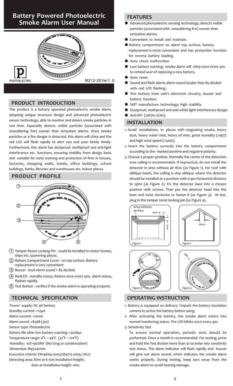
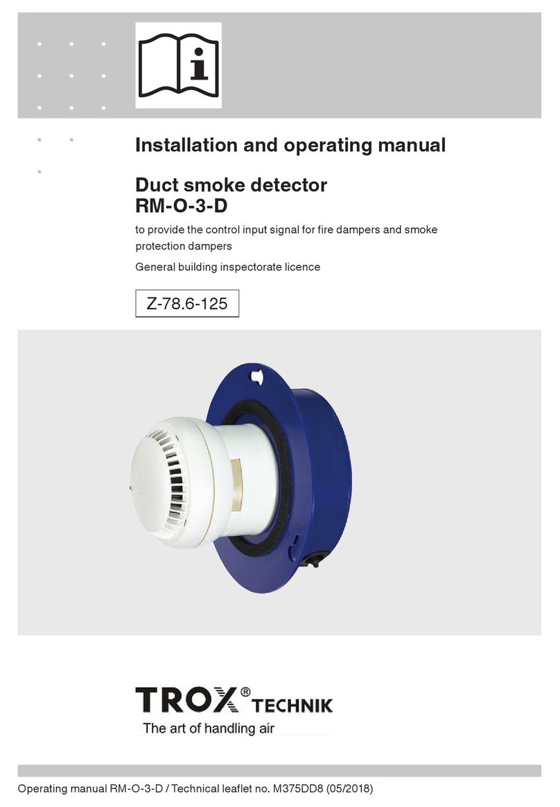
CHELMASH CV212-12 User manual

Smoke alarm
«CV212-12», «CV212-12-01 »
425232.003-01 РЭ
Instruction Manual
INTRODUCTION
The Instruction Manual is designed to study
the structure, functioning and operating
procedures of the Smoke Alarm CV212-12 and
CV212-12-01 (hereinafter referred to as Alarm).
The Alarm meets the requirements of EN-
14604.
1 INTENDED USE
1.1 The Alarm is designed to detect the fire,
accompanied by smoke generation, as well as
issue audible and light signals of fire alert.
1.2 The Alarm can be operated:
- as stand alone;
- in stand alone fire alarm network when
Alarms are combined into a group with two-
wire lines.
1.3 The Alarm is designed for continuous 24×7
operation indoors inside terrestrial stationary
objects.
1.4 Operating conditions:
- Ambient air temperature: between -10 and
50С;
- Relative humidity: up to 95% at a
temperature 35С;
- Atmospheric pressure: between 84 and
107 kPa.
2 SPECIFICATIONS
2.1 Main technical data:
- Sensitivity: not less than 0.05 dB/m;
- Technical availability time:
not more than 15 seconds;
- Power supply voltage: 3V;
- Current consumption: not more than 2 µA;
- Sound volume level at a distance of 3 m: not
less than 85 dB;
- Maximum number of Alarms in a group: not
more than 32;
- Overall dimensions:
diameter –not more than 105 mm,
height –not more than 59 mm.
2.2 Alarm triggering is confirmed by an
audible signal and built-in LED flashing.
2.3 The output signal of triggered Alarm is
not saved after the moment when the effects of
the combustion products complete.
2.4 Alarm weight including a socket, kg: not
more than 0.15.
3 PRODUCT STRUCTURE AND
FUNCTIONING
3.1 The Alarm is an automatic
optoelectronic device for audible and optical
signaling when the smoke density in its location
exceeds the threshold value.
3.2 The Alarm appears as a structure
consisted of the Alarm itself and a base. The
Alarm is connected to the base with a lock.

2
3.3 CV212-12 model contains built-in non-
removable battery inside its housing, in the
housing of CV212-12-01 model the batteries are
removable.
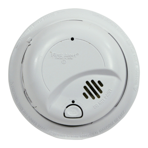
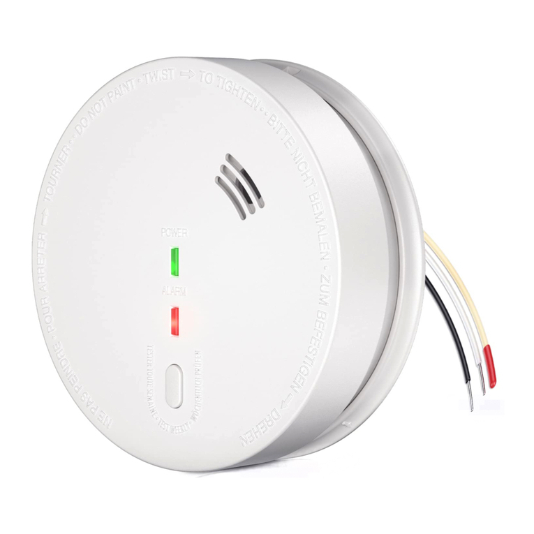
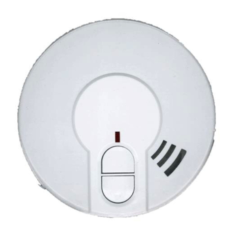
General view of the Alarm is shown in
Fig. 1.
Fig. 1. General view of the Alarm
Отверстие звукового излучателя
Opening of the sound source
Оптический индикатор
Optical indicator
Кнопка "TEST"
TEST button
3.4 The optical indicator of the mode of
operation (red color LED) is located in the Alarm
housing. The “Тест” (Test) button is also located
on the housing
3.5 When the Alarm is in “Standby” mode,
the optical indicator flashes at a frequency of
once in every 6 minutes, when the Alarm
switches to the “Fire" mode the optical indicator
starts flashing with a frequency of once every 1
second, then intermittent audible signal of
variable frequency become active.
4 SAFETY PRECAUTIONS
4.1 The structure of the Alarm provides its
fire safety during operation.
4.2 Installation of the Alarm shall be
carried out by power tool with an operating
voltage up to 42 V and a power up to 40 W,
having proper insulation of live circuits from the
housing of the power tool.
4.3 Installation, replacement and de-
installation of the Alarm shall be carried out
observing the work at height regulation.
5 PRODUCT SETUP AND
INSTALLATION
5.1 The Alarm shall be installed on the
monitored object in accordance with the project
documents, standards, construction standards and
regulations, as well as operational documents of
the Alarm.
5.2 We do not recommend install the
Alarm in places where the release of gases,
vapors and aerosols is possible that can cause
corrosion.
5.3 If repair works are carried out in the
premises where the Alarms are installed, they
shall be protected from the influence of building
materials (whitewash, paint, cement dust, etc.).
5.4 Alarm setup shall be performed in the
following sequence:
5.4.1 Disconnect the Alarm from the base by
turning it counterclockwise (only for CV212-12-
01 option).
5.4.2 Observing the polarity, place power
supply batteries into the housing (only for
CV212-12-01 option).

3
5.4.3 Install the Alarm into the
base.
5.4.4 Press and hold the ТЕСТ (Test) button
for 3–5 s. Optical indicator must start frequently
flashing, and an intermittent audible signal
sounds. After the button is released the audible
and light signals are terminated.
5.4.4 Disconnect the Alarm from the base,
see 5.4.1, and secure the base at the place of
installation using the mounting holes.
2 отв.
2 holes
5.4.5 Install the Alarm into the base. The
Alarm is ready for use.
6 ALARM MODES OF OPERATION AND
DISPLAY
6.1 “Standby” mode
The Alarm for no more than 15 s after its
installation in the base switches to standby mode,
the indicator is flashing once every 6 minutes.
6.2 “Test” mode
Press and hold the “Тест” (Test) button until
the audible signal sounds and LED indication
flashes, then release the button. After a short time
the audible signal terminates.
6.3 “Fire” mode
After the smoke level exceeds the acceptable
value, the Alarm is switched to a “Pre-alarm”
mode (LED indicator flashes frequently), next the
Alarm is switched to a “Fire” mode.
A "Fire" mode is indicated by audible signal
and flashing of built-in LED indicator.
"Fire" mode is not retained after exposure to
combustion products, and the Alarm is switched
to “Standby” mode (see item 6.1).
6.4 “Mute” mode
When the Alarm is switched to a “Fire”
mode (see item 6.3), a "Mute” mode can be
activated by pressing and holding the “Тест”
(Test) button, then the audible signal and “Fire”
mode indication are terminated.

4
When the Alarm is in “Standby" mode (see
item 6.1), to activate this mode press and hold the
“Тест” (Test) button for at least 3 s.
The fact that the Alarm is in the “Mute” mode
is confirmed by LED indicator flashing 1 time per
10 s.
The Alarm autonomously switches to a
"Standby" mode for no more than 10 minutes.
In order to switch the Alarm from a "Mute"
mode to a "Standby" mode, you should press the
“Тест” (Test) button again.
7 GROUPING OF ALARMS
7.1 Alarms may be combined in a group
if you are required that triggering of one alarm
caused triggering of others.
7.2 To combine Alarms in a group, they
are to be connected with the two-wire loop as
shown in the figure:
Fig. 2 Wiring of Alarm by two-wire loop
Вх/Вых
I/O
7.3 In order to combine Alarms in a
group you need to remove the flap on the Alarm
housing:
Observing the polarity, connect the two-wire
loop to the connector of the Alarm:
To
check the operation of Alarm group cause
triggering of any one Alarm. In triggered Alarm
an intermittent audible signal activates, as well as
frequent flashing of the optical indicator. All
other Alarms must issue only audible signals.
8 MAINTENANCE
8.1 At least once every 6 months purge the
Alarm by air during 1 minute from all directions,
using for this purpose a vacuum cleaner or a
compressor with a pressure of (0.5–2) kg/cm2,
and after that test the Alarm.
8.2 You should weekly check the operability
of the Alarm by pressing the “Тест” (Test)
button.
9 POWER SUPPLY BATTERY
Only for CV212-12-01 option.
9.1 When battery low, the Alarm issues
simultaneous short audible and light signals.
To replace the battery, contact your service
provider.
9.2 After the battery replacement, the Alarm
should be tested for compliance to the item 5.4.3.
10 DISPOSAL
10.1 The Alarm models CV212-12,
CV212-12-01 pose no danger to human life and
health, as well as to the environment after the end
of life.
10.2 After the end of life of the battery it
must be removed and disposed separately in
accordance with legislation in forth.
This manual suits for next models
1
