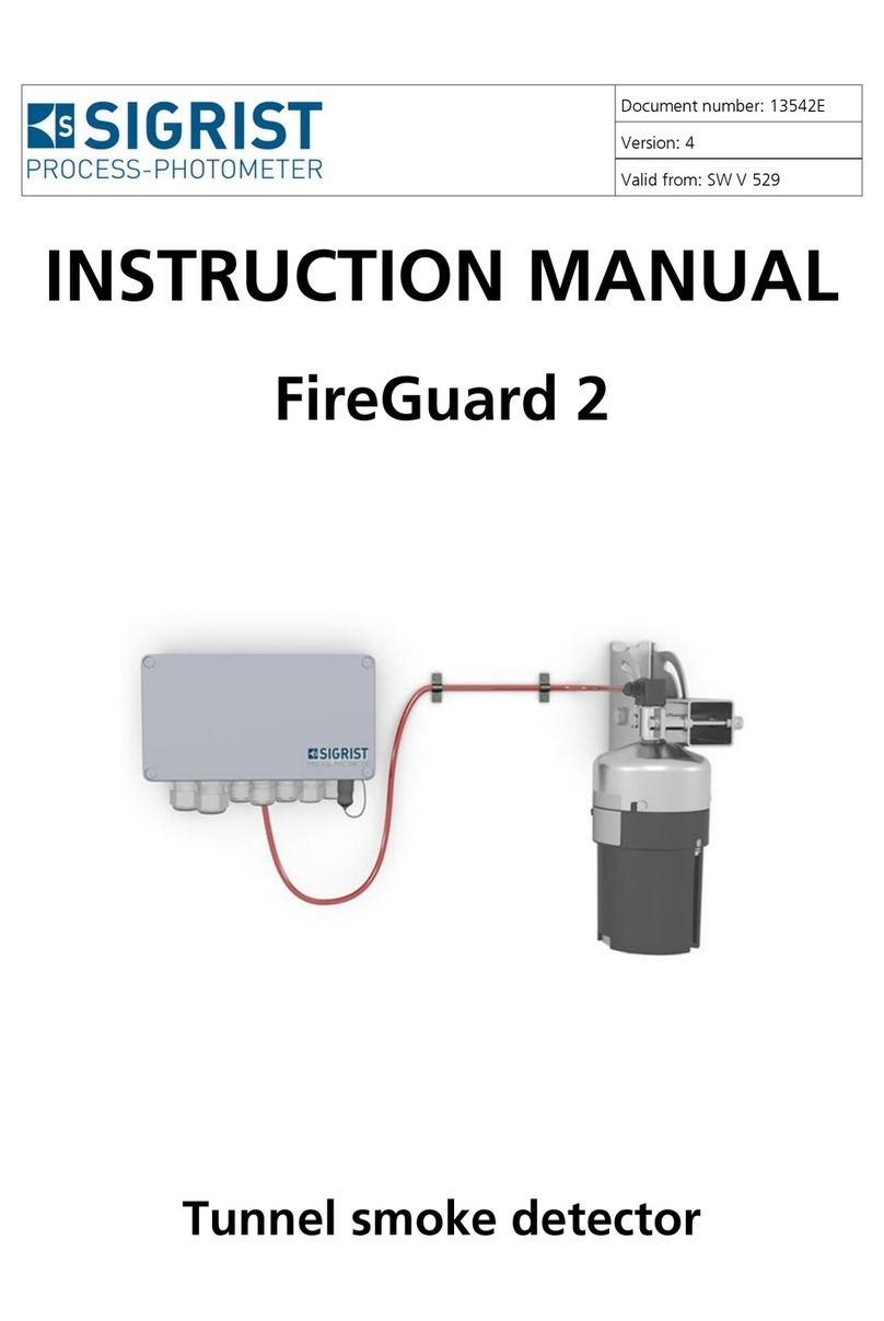
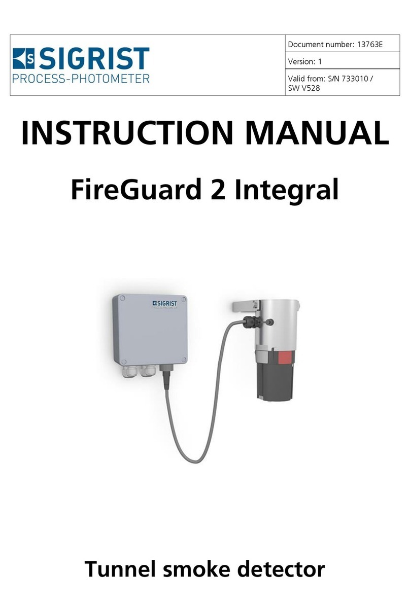
SIGRIST FireGuard 2 Integral User manual

Document number: 13543E
Version: 3
Valid from: SW V129
REFERENCE HANDBOOK
FireGuard 2
Tunnel smoke detector

Copyright© SIGRIST-PHOTOMETER AG, subject to technical changes without notice 5/2020
SIGRIST-PHOTOMETER AG
Hofurlistrasse 1
CH-6373 Ennetbürgen
Switzerland
Tel. +41 41 624 54 54
Fax +41 41 624 54 55
info@photometer.com
www.photometer.com

Contents Reference Handbook FireGuard 2
13543E/3 3
Contents
1General user information...............................................................................................5
1.1 Terms used in this document (glossary).............................................................5
1.2 Purpose of the Reference Manual .....................................................................5
1.3 Target group of the documentation..................................................................5
1.4 Additional documentation ................................................................................5
1.5 Copyright provisions .........................................................................................5
1.6 Document storage location...............................................................................5
1.7 Order document ...............................................................................................6
1.8 Meaning of the safety symbols .........................................................................6
1.9 Meaning of the pictograms...............................................................................7
2Outputs with StromRel module (optional)......................................................................8
3Description of menu functions.......................................................................................9
3.1 General information on the menu description...................................................9
3.2 Menu: Display.................................................................................................10
3.2.1 Submenu: Display\D1 .. n ..........................................................................10
3.3 Menu: Recalibration........................................................................................10
3.3.1 Submenu: Recalibration\General................................................................10
3.3.2 Submenu: Recalibration\C .........................................................................11
3.4 Menu: Sensor check .......................................................................................12
3.5 Menu: Simulation ...........................................................................................12
3.6 Menu: Limits\L1 .. n ........................................................................................13
3.7 Menu: Curr. outputs.......................................................................................14
3.7.1 Submenu: Curr. outputs\General...............................................................14
3.7.2 Submenu: Curr. outputs\S1/2 ....................................................................16
3.7.2.1 Lin/Log function –linear or logarithmic signal output .......................... 17
3.8 Menu: Inp./outputs.........................................................................................17
3.9 Menu: Digi. interf. ..........................................................................................18
3.9.1 Submenu: General.....................................................................................18
3.9.2 Submenu: Modbus RTU (optional) .............................................................19
3.9.3 Submenu: Profibus DP (optional) ...............................................................20
3.9.4 Submenu: Profinet IO (optional).................................................................20
3.10 Menu: Configuration ......................................................................................21
3.11 Menu: Meas.channels \ Cn .............................................................................23
3.11.1 Submenu: Channel C1 Turb ......................................................................23
3.11.1.1 Integration .......................................................................................... 24
3.11.2 Submenu: Channel C2 Turb.Gr..................................................................24
3.11.3 Submenu: Channel C3 Temp.....................................................................25
3.11.4 Submenu: Channel C4 Temp.Gr ................................................................25
3.12 Menu: Spec. function .....................................................................................25
3.13 Menu: Meas. info ...........................................................................................27
3.14 Menu: History.................................................................................................28
3.14.1 History\Fault ..............................................................................................28
3.14.2 Structure of the error messages .................................................................29
3.14.3 History\Adjustment ....................................................................................30
3.15 Menu: System info..........................................................................................31
4Working with the web user interface...........................................................................33
4.1 Working with the web user interface via WLAN..............................................33
4.2 Changing the IP address on PCs with Windows 10 .........................................34
4.3 Start page in measuring operation..................................................................35
4.4 Setting the operating language with web user interface .................................36
4.5 Switching to service operation in the web user interface.................................36
4.6 Button functions in service operation..............................................................37

Reference Handbook FireGuard 2 Contents
4 13543E/3
5Field bus interface .......................................................................................................38
5.1 General...........................................................................................................38
5.1.1 Introduction...............................................................................................38
5.1.2 Fault codes ................................................................................................38
5.2 Modbus RTU / TCP..........................................................................................39
5.2.1 Modbus RTU, general settings ...................................................................39
5.2.2 Address list on the Modbus RTU................................................................39
5.2.3 Function of the live bit in the Modbus .......................................................42
5.3 Profibus DP.....................................................................................................42
5.3.1 Profibus DP, general settings .....................................................................42
5.3.2 Address list on the Profibus DP ..................................................................42
5.3.3 Function of the live fields in the Profibus DP ..............................................45
5.4 Profinet IO ......................................................................................................45
5.4.1 Profinet IO, general settings.......................................................................45
5.4.2 Address list on the Profinet IO (FireGuard 2) ..............................................45
5.4.2.1 GSD file (GSDML-V2.33-SIGRIST-NG PROFINET-20180115.xml)........... 45
5.4.2.2 Measuring data (slot 5: inputs / slot 1: outputs)................................... 46
5.4.2.3 Diagnosis data (slot 6) ......................................................................... 48
5.4.2.4 Configuration data (slot 7: inputs / slot 3: outputs).............................. 48
5.4.2.5 Threshold values (slot 8: inputs / slot 4: outputs) ................................. 49
5.5 HART ..............................................................................................................51
5.5.1 HART, general settings ..............................................................................51
5.5.2 HART process variables ..............................................................................51
5.5.3 Operating several FireGuard 2 units via the SICON M ................................52
6Repair work .................................................................................................................53
6.1 General information on repair work................................................................53
6.2 Replacing the 250 V microfuse on the SIPORT 2 .............................................53
6.3 Replacing the SIPORT 2...................................................................................54
6.4 Replacing the FireGuard 2...............................................................................54
6.5 Replacing the instrument cable on the FireGuard 2.........................................56
7Menu structure & factory settings................................................................................58
8Index ...........................................................................................................................62
Makro
Makro

General user information Reference Handbook FireGuard 2
13543E/3 5
1General user information
1.1 Terms used in this document (glossary)
Please refer to our website for specialist terms: www.photometer.com/en/glossary/
1.2 Purpose of the Reference Manual
This reference manual provides the user with more detailed information that supplements
the Instruction Manual.
1.3 Target group of the documentation
The Reference Manual is intended for all persons who are familiar with the contents of the
Instruction Manual and require detailed information about subjects such as design, configu-
ration, repairs etc.
1.4 Additional documentation
DOC. NO.
TITLE
CONTENT
13542E
Instruction Manual
Contains the most important information about
the overall life cycle of the instrument.
13544E
Brief Instructions
The most important functions and the servicing
schedule.
13654E
Data Sheet
Descriptions and technical data about the instru-
ment.
13545E
Service Manual
Repair and conversion instructions for service en-
gineers.
13692DEF
Declaration of Confor-
mity
Compliance with the underlying directives and
standards.
1.5 Copyright provisions
This document has been written by SIGRIST-PHOTOMETER AG. Copying or modifying the
content or giving this document to third parties is permitted only with the express consent of
SIGRIST-PHOTOMETER AG.
1.6 Document storage location
This document is part of the product. It should be stored in a safe place and always be close
at hand for the user.

Reference Handbook FireGuard 2 General user information
6 13543E/3
1.7 Order document
The most recent version of this document can be downloaded at www.photometer.com
(first time registration required).
It can also be ordered from a SIGRIST representative in your country (→Instruction Manual
“Customer service information”).
1.8 Meaning of the safety symbols
All danger symbols used in this document are explained below:
DANGER!
Danger due to electrical shock that may result in serious bodily injury or death.
Non-observance of this notice may lead to electrical shocks and death.
EXPLOSION
HAZARD!
Danger due to explosion that may result in serious bodily injury or death.
Non-observance of this notice may cause explosions resulting in serious property damage
and death.
WARNING!
Warning about bodily injury or hazards to health with long-term effects.
Non-observance of this warning may lead to injuries with possible long-term effects.
CAUTION!
Notice about possible material damage.
Non-observance of this notice may cause material damage to the instrument and its
peripherals.

General user information Reference Handbook FireGuard 2
13543E/3 7
1.9 Meaning of the pictograms
All pictograms used in this document are explained below:
Additional information about the current topic.
Practical procedures when working with the FireGuard 2.
Manipulations on the touchscreen.
Work on the PC.
The screenshot is an example and may differ from current device.

Reference Handbook FireGuard 2 Outputs with StromRel module (optional)
8 13543E/3
2Outputs with StromRel module (optional)
The StromRel module has two galvanically iso-
lated current outputs (0/4 .. 20 mA). The mi-
nus poles of these outputs are connected to-
gether. The maximum load is 500 Ω.
There are also three semiconductor relays,
which are also galvanically isolated. These are
designed for voltages of up to 30 V and cur-
rents of up to 0.12 A. With the contact clo-
sed, the resistance is 25 Ω.
The functions described in the Instruc-
tion Manual can be assigned to the outputs.
Only two of the three outputs are active (C1
and C2).
Figure 1: Outputs diagram
Two galvanically isolated cur-
rent outputs mA1/2
Galvanically isolated semiconductor re-
lays C1 .. C3

Description of menu functions Reference Handbook FireGuard 2
13543E/3 9
3Description of menu functions
3.1 General information on the menu description
The menus for photometer operation and the web user interface are generally identical.
Differences between the two operation possibilities are separately described in the relevant
sections (e.g. “Setting the operating language” or “Switching to service mode”).
SYMBOL
MEANING
Indicates functions that cannot be changed by the user.
The menu structure with the factory settings is found in the Section 7.

Reference Handbook FireGuard 2 Description of menu functions
10 13543E/3
3.2 Menu: Display
3.2.1 Submenu: Display\D1 .. n
Source
Functions / Values / Parameters
Setting the sequence for displaying the
measuring channels.
The source refers to the channels defined
in the Meas. channels menu.
C1 .. n
▪D1 Turb
▪D2 Turb.Gr
▪D3 Temp
▪D4 Temp.Gr
Inactive
The channel is inactive.
Resolution
Functions / Values / Parameters
Setting the number of decimal points to
be used for the display of small measuring
values.
1, 1.2, 1.23, 1.234
3.3 Menu: Recalibration
3.3.1 Submenu: Recalibration\General
Auto start recal.
Functions / Values / Parameters
Setting whether the recalibration should
be started automatically or not after the
checking unit is inserted.
Inactive
Recalibration is not started
when the checking unit is
inserted.
Active
Recalibration is started au-
tomatically when the
checking unit is inserted.
Cont.1 name
Functions / Values / Parameters
Name of the main checking unit
KStab 1
A maximum of 7
characters can be defined.
Cont.1 value
Functions / Values / Parameters
Nominal value on the main checking unit
Instrument
specific
Value recorded during cali-
bration at the factory.
Cont.2 name
Functions / Values / Parameters
Name of the reserve checking unit
KStab 2
A maximum of 7
characters can be defined.
Cont.2 value
Functions / Values / Parameters
Nominal value on the reserve checking
unit
Instrument
specific
Value recorded during cali-
bration at the factory.

Description of menu functions Reference Handbook FireGuard 2
13543E/3 11
3.3.2 Submenu: Recalibration\C1
Cont. active
Functions / Values / Parameters
Selection of the checking unit to be used
(main/reserve checking unit)
KStab 1
Main checking unit
KStab 2
Reserve checking unit
Nom. val.
Functions / Values / Parameters
Value on the checking unit belonging to
the instrument.
... (instrument specific)
See also:
▪Instruction Manual
...(i nstrume nts pecific)
Act. val.
Functions / Values / Parameters
Current measured value.
... (instrument specific)
See also:
▪Instruction Manual
Adjustment
Functions / Values / Parameters
Initiates adjustment. A new correction fac-
tor is calculated from the actual value and
nominal value.
initiate...
See also:
▪Instruction Manual
Curr. corr.
Functions / Values / Parameters
Current correction factor that specifies the
deviation to the factory settings.
1.000
See also:
▪Instruction Manual
Soiling
Functions / Values / Parameters
Displays the current level of soiling on the
instrument.
▪0% indicates a clean instrument.
▪At 100%, the fouling limit is reached
and a warning message is output on
the instrument.
0 .. 100%

Reference Handbook FireGuard 2 Description of menu functions
12 13543E/3
3.4 Menu: Sensor check
Sensor check
Functions / Values / Parameters
The sensor check includes the inspection
of the entire measuring electronics, plus
all light receivers.
During the check, the actual measu-
rement is not in operation and all output
signals remain frozen in their current
state.
start... .
3.5 Menu: Simulation
Meas.value mode
Functions / Values / Parameters
Measuring values can be simulated on the
outputs with this function.
To be able to clearly differentiate the indi-
vidual measuring values, each channel has
its own multiplication factor for the base
simulation value.
Off
Deactivates the function.
Static
The base simulation value
is 1.
Dynamic
The base simulation value
switches between values
1 to 2.
Simu value
The base simulation value is
taken from the Simu value
parameter.
Simu value
Functions / Values / Parameters
If the function Simu value is adjusted in
the Meas.value mode menu, the value
specified here is taken as the base simula-
tion value.
1.000
See also:
▪Instruction Manual
▪Meas.value mode
Fault mode
Functions / Values / Parameters
All fault messages can be simulated on
the digital interfaces with this function.
Off
Deactivates the function.
See also:
▪Instruction Manual

Description of menu functions Reference Handbook FireGuard 2
13543E/3 13
Curr. outputs
Functions / Values / Parameters
Certain values can be output to the cur-
rent outputs with this function.
Off
Deactivates the function.
0 mA, 4 mA,
8 mA, 10 mA,
12 mA, 16
mA, 20 mA
Electrical current to be out-
put to the outputs.
See also:
▪Instruction Manual
Outputs
Functions / Values / Parameters
Certain states can be output to the digital
outputs with this function.
Off
Deactivates the function.
All Off
All outputs are on 0.
All On
All outputs are on 1.
1 .. n On
Set single output to 1.
Light source
Functions / Values / Parameters
This function can be used to switch the
light source on and off manually for tes-
ting or isolating a fault.
Off
Light source is switched off.
1
Light source is switched on.
3.6 Menu: Limits\L1 .. n
The procedure for setting the limits is described in detail in the Instruction Manual.
For each limit (L1 .. n) the following parameters are available:
Source
Functions / Values / Parameters
Setting the source for the corresponding
limit channel.
L1 Turb
Channel 1
L2 Turb.Gr
Channel 2
L3 Temp
Channel 3
L4 Temp.Gr
Channel 4
Upper limit
Functions / Values / Parameters
Setting the upper threshold value.
... (instrument specific)
See also:
▪Instruction Manual

Reference Handbook FireGuard 2 Description of menu functions
14 13543E/3
Cut in delay
Functions / Values / Parameters
Cut in delay: Setting the time span for
how long the limit has to be exceeded be-
fore a signal is output to the outputs and
appears in the display.
6 s for limit 1 .. 4
8 s for limit 5 .. 8
Value in seconds
See also:
▪Instruction Manual
Cut out delay
Functions / Values / Parameters
Cut out delay: Setting the time span of
how long the limit has to be undershot
before the signal from the outputs drops
out and the limit display disappears from
the display.
0 s
Value in seconds
See also:
▪Instruction Manual
3.7 Menu: Curr. outputs
This menu is active only when a StromRel module is integrated and the module type is set
to StromRel in the Digi. interf. menu under General.
3.7.1 Submenu: Curr. outputs\General
Range
Functions / Values / Parameters
Setting the measuring range MR1 .. MR8.
It is also possible to define the measuring
ranges via inputs In 1/2 or automatically
via Auto 1/2.
MR1 .. MR8
Fixed measuring range
In 1/2
Measuring range switching
via inputs Section 3.8
Auto 1/2
Automatic switching
0/4 mA .. 20 mA
Functions / Values / Parameters
Setting the current range for the reading
output. The output is scaled to each cur-
rent measuring range.
0-20mA
0% measuring value = 0mA,
100% measuring value =
20mA
4-20mA
0% measuring value = 4mA,
100% measuring value =
20mA
See also:
▪Instruction Manual

Description of menu functions Reference Handbook FireGuard 2
13543E/3 15
For service
Functions / Values / Parameters
Setting the measuring value output in ser-
vice mode.
0 Value
During service mode, the
measuring value output is
set to the value that corres-
ponds to measuring value
0. This value depends on
the current range.
Last value
During service mode, the
measuring value output re-
mains (frozen) on the last
valid measuring value.
Recalibr.
During service mode, the
measuring value output re-
mains (frozen) on the last
valid measuring value. Fol-
lowing a manually initiated
calibration check (ad-
justment), a value corres-
ponding to the correction
value is output for 10 se-
conds (see the following
table).
0..20 mA
4..20 mA
Correction value
20 mA
20 mA
1.5
10 mA
12 mA
1.0
0 mA
4 mA
0.5
Measure
The measurement conti-
nues to run normally in ser-
vice mode and the regular
measuring value output is
available. If you are in a
sensor menu, the last va-
lues are maintained.
See also:
▪Instruction Manual
Max. value
Functions / Values / Parameters
Setting the highest possible electrical cur-
rent on the measuring value output. Cur-
rent values over 20.0 mA correspond to
more than 100 % measuring value of the
current measuring range.
21 mA
Adjustable range
20.0 .. 21.0 mA
See also:
▪Instruction Manual

Reference Handbook FireGuard 2 Description of menu functions
16 13543E/3
If fault
Functions / Values / Parameters
Electrical current value that should be out-
put in the event of an error.
This setting is relevant only if 4 mA
.. 20 mA was set as electrical current
range (see above).
2 mA
Adjustable range
0 .. 4 mA
See also:
▪Instruction Manual
3.7.2 Submenu: Curr. outputs\S1/2
The following functions are available for each current output:
Source
Functions / Values / Parameters
Setting the source of the corresponding
current output.
The source refers to the channels defined
in the Meas.channels menus.
Chan. 1 .. 4
Depending on selected
configuration.
Inactive
Range
Functions / Values / Parameters
Setting the measuring range MR1 .. MR8.
MR1 .. MR8
Fixed measuring range
Lin / Log
Functions / Values / Parameters
Setting whether a linear or logarithmic si-
gnal is output on the current output. The
Log value is calculated as follows (see
box):
Log value = log10 (Lin value / MR from) /
log10 (MR to / MR from). MR from has a
minimum value of 0.001 here.
Lin
Linear output
Log
Logarithmic output
See also:
▪Section 3.7.2.1

Description of menu functions Reference Handbook FireGuard 2
13543E/3 17
3.7.2.1 Lin/Log function –linear or logarithmic signal output
The Lin/Log function is used to set whether the current signal is output in linear (Lin) or lo-
garithmic (Log) form.
This can be useful if very large measuring ranges are to be represented, for example
(Example: FireGuard 0.1 .. 3000 mE/m). With the logarithmic signal output, the Measuring
range can have a minimum value of 0.001.
If a lower value was set in the “From” column in the Measuring range menu, then the si-
gnal is output according to this minimum value (there is no underflow). The measuring range
is transferred in a logarithmic range of 0 .. 1. The measuring range is then output as a cur-
rent range of 0/4 .. 20 mA.
The measuring value is converted into a current value as follows:
Log value = log10 (Lin value / MR from) / log10 (MR to / MR from)
Current (4-20mA) = Log value * 16 + 4 [mA]
The current value is converted back into a measuring value as follows:
Log value = (current (4-20mA) –4) / 16
Lin value = MR from * (MR to / MR from) Log value
Example: MR from = 0.1, MR actual = 3000
Lin -> Log -> Current
Current -> Log -> Lin
Lin value
Log value
Current (4 .. 20)
Log value
Lin value
0.1
0.00
4.0
0.00
0.1
1
0.22
7.6
0.22
1
10
0.45
11.1
0.45
10
100
0.67
14.7
0.67
100
1000
0.89
18.3
0.89
1000
3000
1.00
20.0
1.00
3000
3.8 Menu: Inp./outputs
The procedure for setting the outputs is described in detail in the Instruction Manual.
Outputs
Functions / Values / Parameters
O1 Limits
Invert
Invert function.
Fault
Active if a fault has oc-
curred.
O2 Fault
Invert
Invert function.

Reference Handbook FireGuard 2 Description of menu functions
18 13543E/3
3.9 Menu: Digi. interf.
The digital interfaces can be configured here. The available parameters are dependent on the
integrated interface modules (Modbus RTU / Profibus DP/HART).
After changing these options, the instrument must be switched off and then switched on
again. The Modbus RTU/Profibus / Profinet IO / HART menus are displayed only if the con-
cerned modules are installed. →Instruction Manual
3.9.1 Submenu: General
Modul type
Functions / Values / Parameters
Selection of the integrated interface mo-
dule (add-on module).
Auto.
Automatic detection of the
modules after starting the
software.
This does not work
for the HART or StromRel
modules, or when the mo-
dule is integrated in a
connection box such as
SIPORT 2. In such cases, the
Modul type has to be sel-
ected manually.
Module
name…
The selectable modules are
listed according to the
specific instrument (e.g.
Modbus RTU, Profibus DP
etc.)
See also:
▪Instruction Manual
Module location
Functions / Values / Parameters
Selecting the instrument where the inter-
face module was integrated.
Local
If the corresponding mo-
dule is integrated in the Fi-
reGuard 2.
…Name of the
connection
box…
If the corresponding mo-
dule is integrated in a con-
nection box.
See also:
▪Instruction Manual
WLAN-Key
Functions / Values / Parameters
This menu item is only displayed when a
WLAN module is integrated. Entry of the
WLAN security key.
12345678
A maximum of 14
characters can be defined.

Description of menu functions Reference Handbook FireGuard 2
13543E/3 19
3.9.2 Submenu: Modbus RTU (optional)
This menu item is only available when a Modbus module is installed.
Slave no.
Functions / Values / Parameters
Definition of the slave number with which
the photometer is addressed in the con-
trol system.
1
Values between 1 and 240
are permissible.
See also:
▪Instruction Manual
Baud rate
Functions / Values / Parameters
Setting of the baud rate of the Modbus
interface.
115200 Baud
Baud rate in bits/s
Other available values:
4800, 9600, 19200,
38400, 57600, 230400
Baud
Parity
Functions / Values / Parameters
Setting the parity bits of the Modbus in-
terface.
None
No parity bit (NONE)
Even
Even parity bit (EVEN)
Odd
Odd parity bit (ODD)
Stopbit
Functions / Values / Parameters
Setting the number of stopbits on the
Modbus interface.
1
1 stopbit
2
2 stopbits
FireGuard Comp.
Functions / Values / Parameters
Setting the compatibility with the pre-
vious FireGuard version via the Modbus
connection.
If a FireGuard is connected to a
SICON M via the Modbus-Rep pcb, Fire-
Guard Comp. must be deactivated.
Active
Modbus access compatible
with previous version
Inactive
Modbus access compatible
with SICON M

Reference Handbook FireGuard 2 Description of menu functions
20 13543E/3
3.9.3 Submenu: Profibus DP (optional)
This menu item is only available when a Profibus module is installed.
Control
Functions / Values / Parameters
Set whether values can only be read or
can also be written via Profibus.
Local
Values can only be read.
External
Reading and writing the
values. The photometer can
be controlled via Profibus.
Slave no.
Functions / Values / Parameters
Definition of the Profibus slave number.
1
Values between 1 and 240
are permissible.
See also:
▪Instruction Manual
3.9.4 Submenu: Profinet IO (optional)
This menu item is only available when a Profinet IO module is installed.
Control
Functions / Values / Parameters
Setting whether values can only be read
or can also be written via Profinet.
Local
Values can only be read.
External
Values can be read and
written. The photometer
can be controlled via Profi-
net.
Station name
Functions / Values / Parameters
Load the current station name.
Loading the station name results in
a brief interruption in communication.
load...
Other manuals for FireGuard 2 Integral
2
Table of contents
Other SIGRIST Smoke Alarm manuals
Popular Smoke Alarm manuals by other brands

Zipato
Zipato Z-Wave PH-PSG01 Quick installation guide
Universal Security Instruments
Universal Security Instruments HEAT ALARM USI-2430 owner's manual

olympia electronics
olympia electronics BS- 657/A quick start guide

Brooks
Brooks Electronics EIB603CX user guide
Z-Wave
Z-Wave SF813 manual
Seca
Seca Model S Installation and operating instruction
