Chemessen ROPPOR User manual


2/17
Legal Disclaimer
※ Legal Disclaimer Regarding Copyright
ROPPOR Swarm Drone Software is registered with the Korea Copyright Commission and is protected
by copyright law.
Please note that unauthorized copying, use, and distribution of this software, as well as unauthorized
copying, use, and distribution of functions, function lists, function placement, user interfaces, and
design within the software, are in violation of copyright law.
ROPPOR Swarm Drone Trial Software may only be used for functional verification purposes, and
may not be used for commercial, educational, or business purposes.
If you have any copyright-related questions, please send your inquiries to staff@roppor.com and we
will sincerely review and respond.
※ Legal Disclaimer Regarding Limitation of Liability
ChemEssen Inc. is a software company. We are only responsible for the development and supply of
swarm drone software and does not actually operate drone aircraft. The hardware related to parts
and equipment, etc. and data such as mobile communication networks provided by us is only one
example of testing the products of various manufacturers and the services of mobile carriers and
confirming their integration with our software, and the durability of each hardware and mobile
communication network.
It does not guarantee the stability, the function for a specific purpose, etc.
The user is solely responsible for the selection, interlocking, and operation results of all hardware
and mobile communication networks outside the scope of the software.
Please select the hardware and mobile communication network that suits your purpose using the
free trial version, which is provided unlimitedly regardless of the duration and number of drones,
and be sure to verify its function, durability, stability, and malfunction. In addition, it is necessary to
check and comply with the relevant laws and regulations of the country when drones are actually
operated.
In addition to the software, the civil and criminal liability for all unforeseen circumstances and illegal
operation including errors, malfunctions, accidents, human damages and property damages that
may occur during interlock and operation of the drone body, parts, equipment, and mobile
communication network selected by the user lies with the user, not with ChemEssen, Inc.

3/17
INDEX
Legal Disclaimer.....................................................................................................................................................2
※ Legal Disclaimer Regarding Copyright............................................................................................2
※ Legal Disclaimer Regarding Limitation of Liability...................................................................2
1. H/W List .................................................................................................................................................................5
1-1. LTE Device & Companion Computer...............................................................................................5
1) Raspberry Pi 3A+ or 3B+ ...............................................................................................................5
2) 16GB Micro SD Memory Card......................................................................................................5
3) Quectel EC25 Mini PCle 4G/LTE Module.................................................................................5
4) LTE Full Band PCB Antenna –u.FL Plug –100mm .............................................................5
5) Sixfab Raspberry Pi 3G/4G<E Base HAT.............................................................................5
1-2. Drone..............................................................................................................................................................5
1) Drotek Pixhawk 3 Pro.......................................................................................................................5
2) Drotek All-in-One module (Pixhawk 3 pro) ...........................................................................5
3) Drotek Voltage & current & 5.3V power supply –Mounted........................................5
4) JST-GH to JWT 28AWG 6-pins Silicone cable.......................................................................5
5) Drotek SIRIUS RTK GNSS ROVER (F9P)....................................................................................5
1-3. Recommendations....................................................................................................................................6
2. Companion Computer & LTE Device........................................................................................................7
2-1. Preparation ..................................................................................................................................................7
1) Main Power Cable..............................................................................................................................7
2-2. Connection...................................................................................................................................................8
1) Companion Computer .....................................................................................................................8
2) LTE Device .............................................................................................................................................8
3) Companion Computer & LTE Device........................................................................................9
2-3. Connect ...................................................................................................................................................... 10

4/17
3. LED Board........................................................................................................................................................... 12
3-1. Preparation ............................................................................................................................................... 12
3-2. Connect ...................................................................................................................................................... 13
4. Firmware and Parameter ............................................................................................................................. 14
4-1. Firmware Installation ............................................................................................................................ 14
4-2. Parameter Change................................................................................................................................. 14
5. Check Wireless Communication and Connection............................................................................ 16

5/17
1. H/W List
1-1. LTE Device & Companion Computer
1) Raspberry Pi 3A+ or 3B+
2) 16GB Micro SD Memory Card
3) Quectel EC25 Mini PCle 4G/LTE Module
https://sixfab.com/product/quectel-ec25-mini-pcle-4glte-module/
4) LTE Full Band PCB Antenna –u.FL Plug –100mm
https://sixfab.com/product/lte-full-band-pcb-antenna-u-fl-plug-100mm/
5) Sixfab Raspberry Pi 3G/4G<E Base HAT
https://sixfab.com/product/raspberry-pi-base-hat-3g-4g-lte-minipcie-cards/
1-2. Drone
1) Drotek Pixhawk 3 Pro
https://store-drotek.com/821-pixhawk-pro-autopilot.html
2) Drotek All-in-One module (Pixhawk 3 pro)
https://store-drotek.com/819-all-in-one-Pixhawk.html
3) Drotek Voltage & current & 5.3V power supply –Mounted
https://store-drotek.com/809-voltage-current-53v-power-supply-mounted.html
4) JST-GH to JWT 28AWG 6-pins Silicone cable
https://store-drotek.com/831-jst-gh-to-jwt-28awg-6pins-cable.html
5) Drotek SIRIUS RTK GNSS ROVER (F9P)
https://store-drotek.com/911-1007-sirius-rtk-gnss-rover-f9p.html#/157-sensor-rm3100

6/17
1-3. Recommendations
-Most common cause of collision between drones and drone crash are loose
connections, screw tightening, cable damage, and defective soldering in drone
manufacturing. Assemble with care.
-The shape of drone and overall hardware composition are user’s choice.
-The company introduces the guide for connection with LTE based ROPPOR software a
fter taking the shape of a general drone (quad-copter).
7/17
2. Companion Computer & LTE Device
LTE devices that can connect with Raspberry Pi are constantly being updated by Sixfab, so user’s
drone weight reduction and compact shape change are possible through hardware update and
connection test.
: https://sixfab.com/product-category/raspberry-pi-shields/
2-1. Preparation
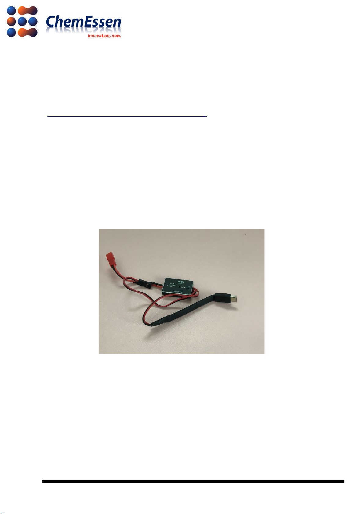
1) Main Power Cable
Prepare the main power (5V) cable to supply power to the micro USB power of Raspberry Pi. This
cable is not provided and thus can assemble your own power cable.
※The company has supplied power by connecting 5V/3A UBEC to the PDB (12V) of the drone.
The method of the company does not guarantee drone control for the user.
Figure # 1 Main Power Cable

8/17
2-2. Connection
Prepare a micro SD card installed with the Smart Device Application Software(SDAS), Raspberry Pi,
LTE module, and LTE base hat.
※ For SDAS software installation method , please refer to the Smart Device Application
Software Installation Document.
Connect as follows.
1) Companion Computer
Insert the micro SD card installed with SDAS to Raspberry Pi.
Figure # 2 Raspberry Pi 3A+ Layout
2) LTE Device
Mount the LTE module to the mini PCIe socket of the LTE base hat. Then insert the activated USIM
into the SIM socket.
Figure # 3 LTE Base Hat/EC25 LTE Module Layout
9/17
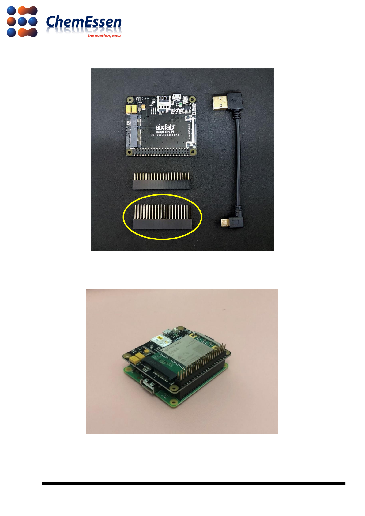
Use the long header to connect the Raspberry Pi and the LTE base hat.
Figure # 4 Component - Long Header
3) Companion Computer & LTE Device
Figure # 5 Result of Connection

10/17
2-3. Connect
Connect the connected devices as follows.
1) Use the USB to micro USB cable to connect the Raspberry Pi and the LTE base hat.
2) Connect the LTE full band PCB antenna to the MAIN and DIY of the LTE module.
Figure # 6 Connection Result by Device
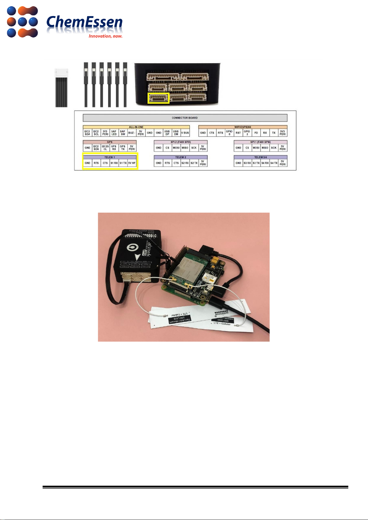
3) Use the JST-GH to JWT 28AWG 6-pins silicone cable to connect to the GND, TX, and RX of the
LTE base hat to Telem1 port of Pixhawk 3 Pro. Make sure that the cable connected to the long
header is stable.
Figure # 7 LTE Base Hat Pinout
11/17
Figure # 8 JST-GH to JWT 28AWG 6-pins Silicone cable/Pixhawk 3 Pro Pinout
4) Last, connect the main power line to the micro USB power of the Raspberry Pi.
Figure #9Final Result
※ The method of the company does not guarantee drone control for the user.

12/17
3. LED Board
Refer to the following link for the LED board.
: https://github.com/ugcs/ddc/tree/master/Drone_hardware/3D_Printing
3-1. Preparation
The LED board in the link above consists of PCB, main power line, and JWT 3-pin(Servo Signal)
cable. Prepare a cable to supply main power to the LED board and a cable to receive LED signal
from FC.
Figure # 10 LED Board PCB/Cable Composition Example

13/17
※ You must select, develop, and apply the hardware such as LED after considering the price c
ompetitiveness and performance of the hardware for performance with ROPPOR Art. Therefo
re, LED should be operational with low power, and we recommend that you search for and a
pply mass produced LED that can maintain the same level of brightness for all drones, or to
mass produce and apply such LED.
3-2. Connect
Figure # 11 Pixhawk 3 Pro Pinout/LED Board Connect
Connect the main power cable to supply power to the LED board. Then connect the RGB signal
cable to the servo rail indicated as “R – 1”, “G – 2”, and “B – 3”.
14/17
4. Firmware and Parameter
ArduPilot is continuing to update the firmware so you can access improved flight control and
advanced control technology through tests.
: https://firmware.ardupilot.org/Copter/
4-1. Firmware Installation
Install the Mission Planner for firmware installation and hardware/software configuration.
: https://firmware.ardupilot.org/Tools/MissionPlanner/
Refer to the following document for basic firmware installation method.
: https://ardupilot.org/copter/docs/common-loading-firmware-onto-pixhawk.html#connect-
autopilot-to-computer
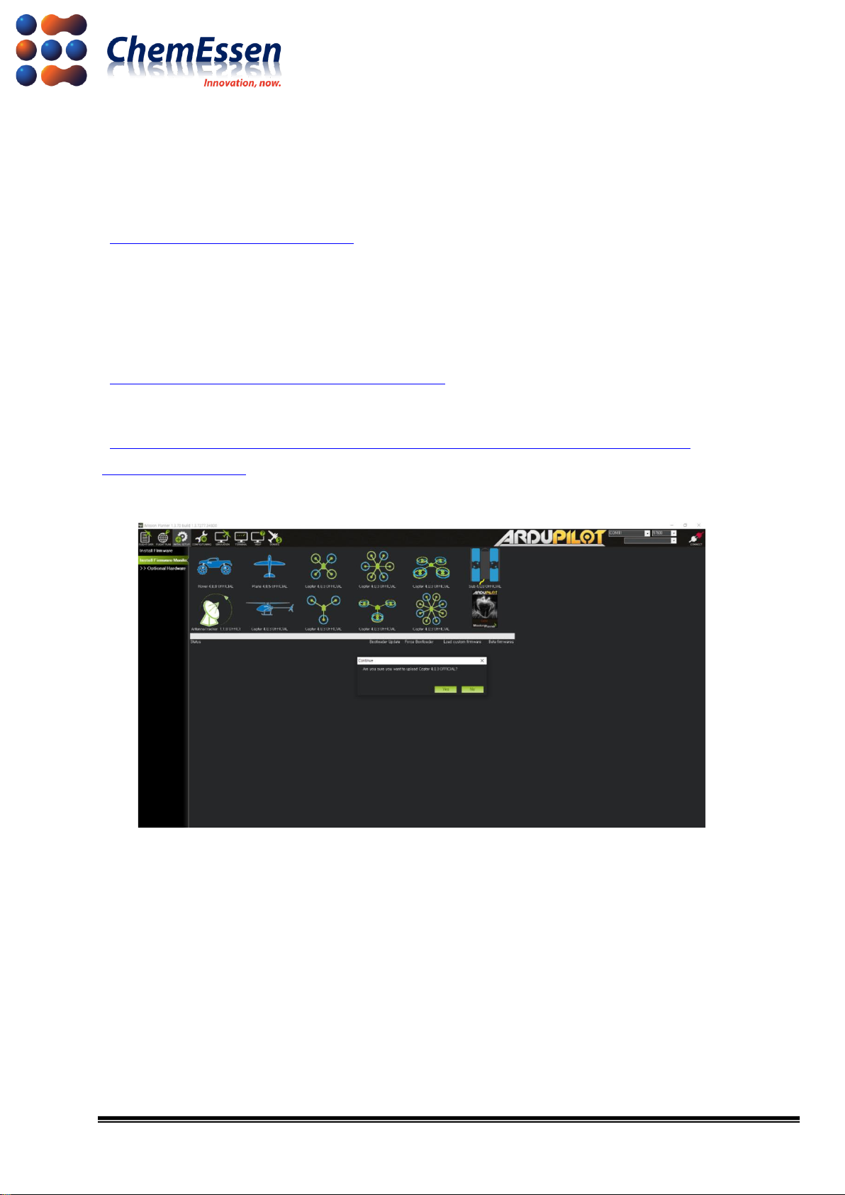
※ The company has completed the final test with Arducopter V4.0.3 Quad.
Figure # 12 Mission Planner - Firmware Installation Screen
Use USB to micro USB to connect the PC and FC, and then use the Mission Planner to install the
suitable firmware for the drone.
4-2. Parameter Change
Change the Baudrate value of Telem1(based on Pixhawk 3 Pro, SERIAL1_BAUD) port connected
for communication between Raspberry Pi and FC to “115200” (Default value : 57600).
15/17
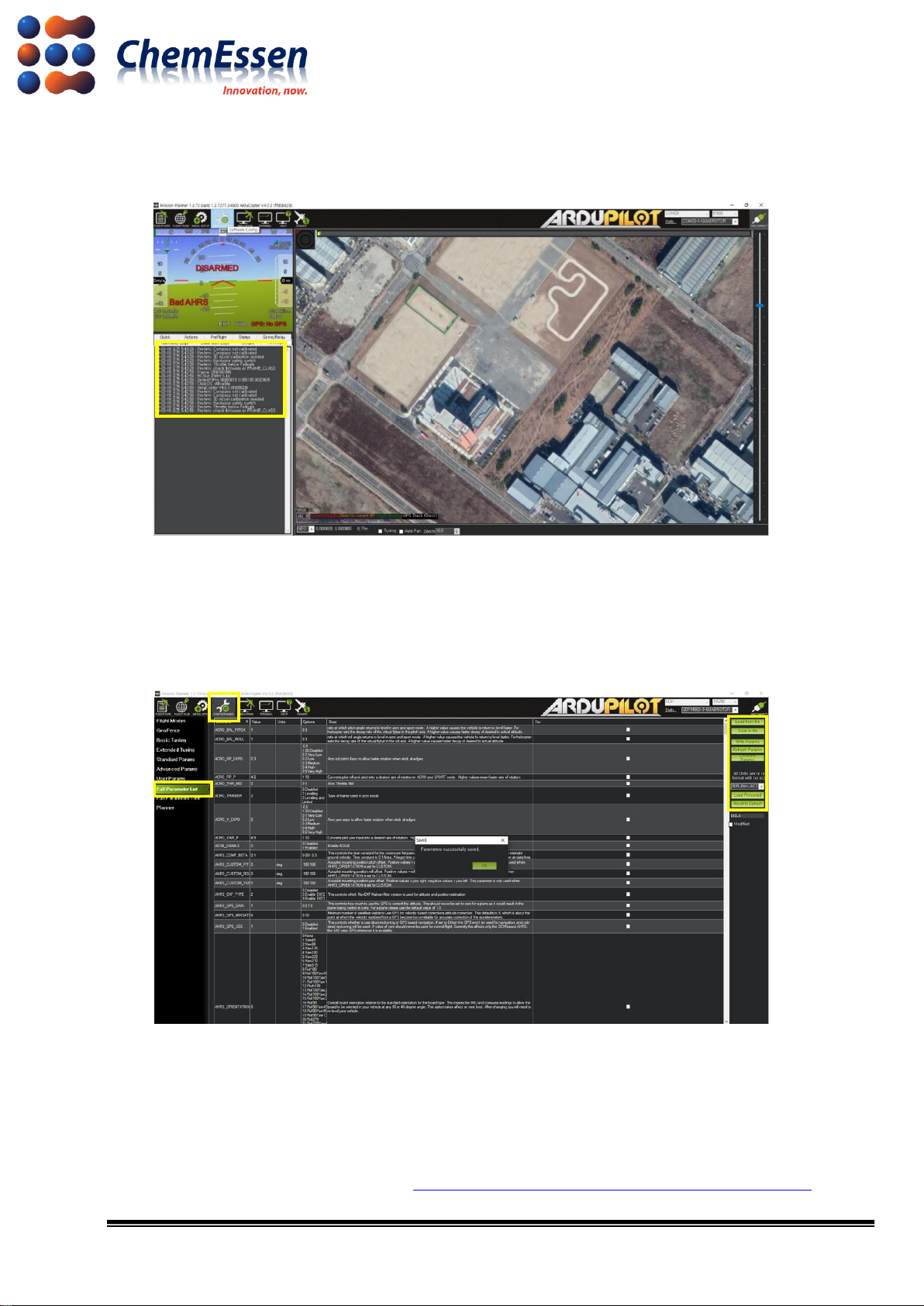
1) After firmware installation is complete, connect the FC and PC with USB to micro USB, and check
that the version is correct through the Mission Planner.
Figure # 13 Mission Planner Message log –ArduCopter V4.0.3(ffd08628)
2) In Config/Tuning of the Full Parameter List, change the Baudrate value of Telem1(based on
Pixhawk 3 Pro, SERIAL1_BAUD) port to “115200” (Input value : 115). And then click [Write Params]
to apply and save.
Figure # 14 Mission Planner Configuration –Full Parameter List
※Parameter values suggested by the company is irrelevant to the user’s drone control.
Configure and check the parameters according to user operation and hardware configuration
aside from other applicable values before operation.
Full parameter list provided by ArduPilot : https://ardupilot.org/copter/docs/parameters.html
16/17
5. Check Wireless Communication and Connection
When parameter changes are complete, the drone can wirelessly communicate with the operation
PC (After completing the configuration of SDAS, VPN, etc.). Wireless communication is checked as
follows.
1) Launch ROPPOR to check wireless communication. Disconnect the wired connection between the
PC and the drone, and power the drone with a battery.
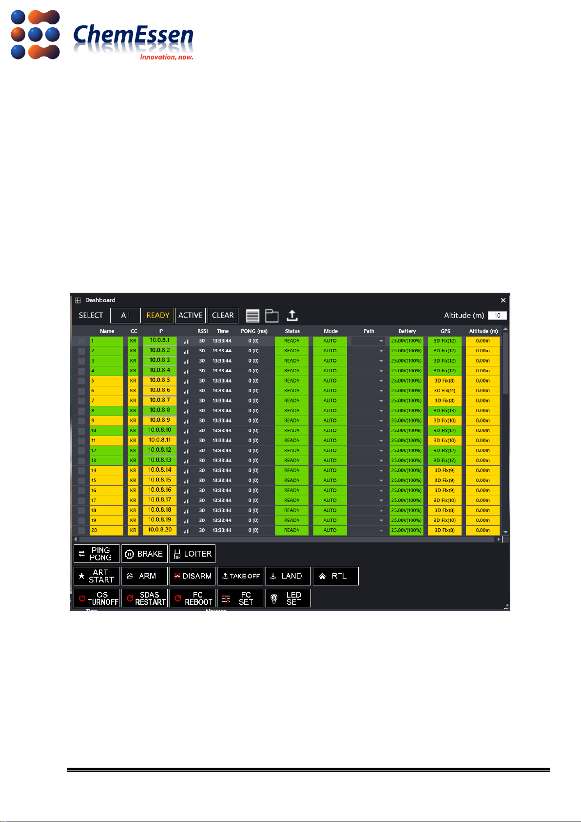
2) Rebooted drone is displayed on the ROPPOR screen within minutes, and you can check the IP
for the drone in the [Dashboard].
Figure # 15 Check Connection in ROPPOR Dashboard - IP

17/17
3) Change the communication method of the mission planner to TCP, change the baud rate value
to 115200, and then click [Connect]. Enter the IP for the drone in the remote host pop-up window,
and enter “14000” in the remote port pop-up window, and try to connect. You can check the
attempt of wireless communication trying to open the parameters.
Figure # 16 Mission Planner Connect –Remote Host/Port
Figure # 17 Mission Planner –Wireless Communication Check
※Configure according to the type and specifications of the drone such as frame type, accel
calibration, compass, etc. After completing the flight test, use the ROPPOR software to fly.
Configuration provided by ArduPilot
: https://ardupilot.org/copter/docs/configuring-hardware.html
Table of contents


