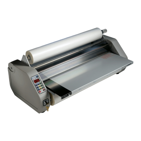
ChemInstruments HL-200 User manual

HOT ROLL LAMINATOR
MODEL HL-200/201
OPERATING INSTRUCTIONS
CHEMINSTRUMENTS
510 COMMERCIAL DRIVE
FAIRFIELD, OHIO 45014
(513) 860-1598
www.cheminstruments.com
Revision 1.0
July 31, 2018

TABLE OF CONTENTS
PRODUCT DESCRIPTION........................................................................................................ 3
SPECIFICATIONS.......................................................................................................... 4
UNPACKING ............................................................................................................................. 5
ASSEMBLY ............................................................................................................................... 6
SAFETY FEATURES................................................................................................................. 7
KEY COMPONENTS................................................................................................................. 8
THEORY OF OPERATION.......................................................................................................11
POWER UP...................................................................................................................11
OPERATION.................................................................................................................11
PROGRAMMABLE HEAT CONTROLLER....................................................................14
LAMINATING PROCEDURE.........................................................................................15
EXHAUST CONTROL VALVES ....................................................................................16
OPTIONAL EQUIPMENT..........................................................................................................17
GAP ADJUSTERS.........................................................................................................17
BRAKE UNWIND STAND..............................................................................................18
PNEUMATIC FOOT CONTROL....................................................................................19
MAINTENANCE........................................................................................................................20
TROUBLESHOOTING ..................................................................................................20
MAINTENANCE PROCEDURES ..................................................................................21
REPLACEMENT PARTS ..........................................................................................................25
2 | Page
Hot Roll Laminator Operating Instructions (HL-200/201)

PRODUCT DESCRIPTION
Congratulations on the purchase of your new ChemInstruments HL-200/201 Hot Roll Laminator.
This is a state of the art laboratory laminator with balanced pneumatic pressure top roll and
controlled heat.
Warning: This equipment can cause injury if not used properly. It is the
operator’s responsibility to observe all safety rules and warnings.
This unit has the following features:
•Model HL-200 includes hard coat anodized Teflon coated aluminum top roll.
•Model HL-201 includes chrome plated steel top roll.
•Programmable temperature heat controller.
•Single unwind stand.
•Safety features that include a laminator nip trip wire and an emergency stop button.
•Optional heat guard kit is available providing guards for the top and bottom laminating
rolls as well as the end cap roll shaft and bearings.
•Optional gap adjusters for precise gap control during laminating.
•Optional separate brake unwind stand for additional unwind with brake tension control.
•Forward and reverse action of the drive roll
•Selectable speeds from 2 – 300 inches per minute (5 – 750 centimeters per minute) in
either direction
•Continuous run and jog mode
3 | Page
Hot Roll Laminator Operating Instructions (HL-200/201)

SPECIFICATIONS
Electrical
120 VAC, 50/60 Hz, 15 amps or 240 VAC, 50/60 Hz, 8 amps
Air Pressure
40 – 100 PSI
Speed 2 – 300 inches/minute (0.1 inch increments from 2-12, 0.5 inch
increments from 12-300)
5 – 750 centimeters/minute (.25 centimeter increments from 5-30,
1.25 centimeter from 30-750)
Max opening at Nip
2 inch (51 millimeter)
Physical
Dimensions Width: 39 inches (99 centimeters)
Depth: 20 inches (51 centimeters)
Height: 30 inches (76 centimeters)
Weight: 160 pounds (73 kilograms) with an Aluminum Roll
Weight: 185 pounds (84 kilograms) with a Steel Roll
4 | Page
Hot Roll Laminator Operating Instructions (HL-200/201)

UNPACKING
ChemInstruments has made every effort to ensure that the HL-200/201 arrives at your location
without damage. Carefully unpack the instrument and check for any damage that may have
occurred during shipment. If any damage did occur during transit, notify the carrier
immediately.
The ChemInstruments HL-200/201 consists of the following parts:
•The laminator frame, which includes the laminating station and attached control box.
•Optional equipment if ordered would include gap adjusters, brake unwind stand, heat
guard kit, along with any customized alterations and/or additions.
Make sure all of these components are present before discarding the packaging material.
HL-200 with optional gap adjusters
5 | Page
Hot Roll Laminator Operating Instructions (HL-200/201)

ASSEMBLY
Warning: Due to its weight and size, use two people to move the HL-200/201.
Warning: Before proceeding with using the HL-200/201, it is advisable to
become familiar with the Key Components. These Key Components and a brief
description of their function follow in the next section.
•Carefully remove the Hot Roll Laminator from the packaging and set it on a sturdy bench
top.
•Check the physical dimensions listed previously for the space required for the
instrument. As with any precision piece of laboratory equipment, it is preferable to locate
the HL-200/201 in an area where temperature and humidity are controlled to standard
conditions of 72 ± 2°F and 50 ± 5% relative humidity.
•The laminator should be located on a sturdy bench or cart capable of a 200 pound load.
•It is recommended that access be provided for both the front and back of the machine.
•Carefully remove the Kraft paper from the laminating rolls.
•Attach an incoming airline to the male inlet fixture on the side of the cabinet.
•Set the Air Pressure Regulator at 40 PSI for initial startup.
Warning: Make sure the power source matches the requirements of the Hot Roll
Laminator machine. Damage will occur if this unit is plugged into the incorrect
power supply.
Warning: Only connect this unit to a properly sized circuit to avoid overload
problems.
•Plug the laminator into the appropriate AC circuit.
•Remove the wood blocks between the laminating rolls. This requires the air and
electrical connections to have been made. Push the OPEN NIP button if the top Heat
Laminating Roll is in the down position and resting on the wood blocks.
•If the optional Gap Adjusters are included, use these to create a gap by threading both
lower half of the Gap Adjuster cylinders down the air cylinder shaft. Lock their position
by threading the top half of the Gap Adjuster down until it contacts the bottom half of the
Gap Adjuster.
6 | Page
Hot Roll Laminator Operating Instructions (HL-200/201)

•When the laminator is not in use, these Gap Adjusters will provide a mechanical stop to
the downward travel of the top Heat Laminating Roll. This will prevent wear and damage
to the rubber cover on the Drive Laminating Roll
•Check the Roll Unwind Bar to make sure it is seated properly in the support frame.
•If the optional Brake Unwind System is provided, check that the Pressure Plate is
positioned with the slot over the Retaining Pin.
The HL-200/201 laminator is now ready for use except for setting the temperature level for the
heated roll.
SAFETY FEATURES
The HL-200/201 hot roll laminator should be considered as any other piece of laboratory
equipment. The safety features incorporated in this device are designed to help prevent injury.
It remains the operator’s responsibility to use this and all equipment with caution while following
the manufacturer’s instructions. Basic common sense and caution should be exercised at all
times.
Please pay attention to and follow all warnings and cautions as you use this equipment. There
are two basic safety features for this device.
1. TRIP WIRE:This safety wire is located in front of the top Heat Laminating Roll and nip
point. When activated, the top roll will travel upward, opening the laminating nip and
removing the pressure between the two laminating rolls. This trip wire is adjustable and
should be tested regularly to insure proper operation. DO NOT REMOVE THIS
DEVICE. It is considered a safety violation to hinder the operation of this device in any
manner.
2. E-STOP:This device is located on the side of the control cabinet for ease of access.
Besides disrupting all power to the equipment when activated, the top Heat Laminating
Roll will travel upward opening the nip point of the two laminating rolls. This switch is not
to be used as an “on/off” switch when operating the HL-200/201 laminator.
7 | Page
Hot Roll Laminator Operating Instructions (HL-200/201)

KEY COMPONENTS
CONTROL CABINET SIDE PANEL
•PRESSURE REGULATOR controls the air pressure distributed to the air pistons.
•E-STOP emergency stop disrupts all electrical and air supply, turn to release.
•AIR INLET CONNECTION is the connection for the air source.
Air Inlet
Connection
E-Stop
Pressure
Regulator
AC Power
Connection
8 | Page
Hot Roll Laminator Operating Instructions (HL-200/201)

LAMINATOR
•EXHAUST CONTROL VALVES control the rate of exhaust from the Air Cylinder that it is
mounted to.
•AIR CYLINDERS are mounted vertically at each end of the top heat laminating roll.
These pneumatic cylinders move the top heat laminating roll up and down according to
the UP and DOWN switches.
•HEATED LAMINATING ROLL the top roll supplying the laminating pressure.
•DRIVE LAMINATING ROLL the bottom roll connected to the motor and supplying the
drive to the laminator.
•NIP refers to the point of contact between the two laminating rolls.
•SAFETY TRIP WIRE will open the nip by raising the heat laminating roll. The heat
laminating roll will stop moving also.
Exhaust Control Valves
Air Cylinders
Optional Gap Adjusters
Heat Laminating Roll
Safety Trip Wire
Drive Laminating Roll
9 | Page
Hot Roll Laminator Operating Instructions (HL-200/201)

CONTROL CABINET FRONT PANEL
•PROGRAMMABLE HEAT CONTROLLER allows you to set temperature and offset
parameters.
•OPEN NIP moves top pressure roll to the up position.
•CLOSE NIP moves top pressure roll to the down position.
•PRESSURE GAUGE displays the air pressure being delivered to the air pistons after
passing through the Pressure Regulator.
•MAIN POWER SWITCH turns on/off the AC power to the machine.
•HEAT POWER SWITCH turns on/off the heat controller.
•CONTROL PANEL SWITCHES – See Control Panel Operation in Section 5.0, Theory of
Operation, for a description of the functions of these switches
Programmable Heat Controller
Control
Panel
Switches
Heat
Power
Switch
Main
Power
Switch
Pressure Gauge
Up
(Open
Nip)
Down
(Close
Nip)
10 | Page
Hot Roll Laminator Operating Instructions (HL-200/201)

THEORY OF OPERATION
Warning: Possibility of crushing or pinching. 1) Do not insert limbs in the nip
area while rolls are rotating. 2) Do not lower the top roll while limbs are in the nip
area.
Laminated samples can be prepared with or without heat. Single sample sheets to be
laminated are fed to the Nip from the Laminating Platforms to be laminated with material from
the Unwind Stand. The top Heat Laminating Roll can be controlled to provide heat for heat
activated adhesive material. Laminating pressure is controlled by the Air Regulator. Speed and
direction of the laminating rolls is controlled by the control board. The travel speed of the top
Heat Laminating Roll is controlled by the four Exhaust Control Valves.
Each of the items mentioned above can be found in various sections of this manual with a detail
explanation of their function and method of operation.
POWER UP
Turn on the main power switch located on the front panel of the control cabinet. The display will
go through a power on self-test. It is also necessary to open the air supply valve.
Warning: Operating temperature for this equipment is 0 to 70 Celsius. The
equipment needs to be completely free of condensation, inside and out, before
applying power.
OPERATION
PRESSURE REGULATION
Turning the Pressure Regulator knob, located on the top of the control cabinet, controls the
pressure of the top roll at the nip. Turning the knob clockwise will increase the pressure and
turning it counter clockwise will decrease the air pressure. The Pressure Gauge, located on the
front of the control cabinet, will display the current air pressure on the top pressure roll.
FLOW CONTROL VALVES
The Flow Control Valves regulate the speed of the top pressure roll as it moves up and down.
Adjusting the valves in the following manner will regulate this movement. It may also be
necessary to adjust these valves to balance the movement of the air pistons in order for the top
11 | Page
Hot Roll Laminator Operating Instructions (HL-200/201)

pressure roll to travel evenly. If the speed of the two air pistons is not equal, one side of the top
pressure roll will move faster than the other side.
Warning! Always operate with the top rolls downward motion at a slow speed.
The speed of the air pistons has been preset at the factory. These settings allow the top
pressure roll to move downward at a safe, slow speed, and move upward rapidly. If it becomes
necessary to adjust these valves, then use the following procedure.
•The bottom valve controls the down speed and the top valve controls the up speed.
•Turn the thumbscrews clockwise to go slower and counter clockwise to go faster.
•After each adjustment move the top pressure roll up by pressing the RED OPEN button
and down by pressing the GREEN CLOSE button at least one time to determine the
affect and need for further adjustment.
•Always maintain an even balance between the left and right Flow Control Valves to
avoid uneven movement of the top pressure roll when traveling up and down.
CONTROL PANEL OPERATION
The HL-200/201 instrument allows the user to change speed and direction of the drive roll while
it is moving.The control panel has a circular menu system. See Table 1 for a listing of
selectable parameters.
The following describes the button operation for the Control Panel:
1. START/STOP: Pressing this button while there is no motion will move the drive roll at
the set speed and direction as long as the Nip is in the lowered position. Pressing this
button while the rolls are moving will cause motion to stop.
2. JOG: While this button is pressed, the rolls will move at the set speed and direction
programmed as long as the Nip is in the lowered position. As soon as this button is
released, motion will stop.
3. ENTER: This button is used to change the parameter displayed on the top line of the
display. The display has a circular menu system.
4. UP ARROW, DOWN ARROW: These buttons will alter the value of the parameter that is
displayed on the top line of the display. The values can be changed either when the
rolls are moving or stationary.
The procedure for changing parameter values is as follows:
1. Press the ENTER button to change the parameter displayed on the top line.
2. The parameter displayed on the top line of the display can be altered by using the UP
ARROW and DOWN ARROW.
3. The values can be changed while the rollers are moving.
12 | Page
Hot Roll Laminator Operating Instructions (HL-200/201)

4. For example, to change speed, press the ENTER button until the speed is displayed on
the top line of the display. Press the UP ARROW or DOWN ARROW until the desired
speed is displayed.
Table 1 - Parameters and Ranges
Speed 2 – 300 inches/minute (0.1 inch increments from 2-12, 0.5 inch increment
from 12-300)
5 – 750 centimeters/minute (0.25 centimeter increments from 5-30, 1.25
from 30-750)
Direction
Forward or Reverse
Units
Inches or centimeters
Length The displayed value is the measured length traveled since the last reset.
This value is always incrementing even when the motor is reversed. If
changing direction, then reset the length traveled by pressing the Up
Arrow or the Down Arrow while the Length is displayed on the top line of
the display.
INSTRUMENT OPERATION
The following describes basic instrument operation:
1. Press the GREEN CLOSE NIP button to close the Nip.
2. Move the rolls by pressing the START/STOP button or the JOG button.
3. Change the speed or direction by following the procedure listed in Control Panel
Operation.
4. Reset the displayed length by pressing the UP ARROW or DOWN ARROW while the
Length is displayed on the top line of the display.
5. Press the RED OPEN NIP button to open the Nip.
13 | Page
Hot Roll Laminator Operating Instructions (HL-200/201)

PROGRAMMABLE HEAT CONTROLLER
There is a separate manual supplied by the manufacturer of the Heat Controller. Please refer to
this manual for specific instructions on operation.
One of the features of the Programmable Heat Controller is the ability to learn the fastest most
efficient manner to reach the set temperature. This feature is called “Auto Tune”. Before
shipping, the HL-200/201 has been Auto Tuned to 250 º F (122 º C).
1. To activate the top Heat Laminating Roll heat, turn the Heat Power Switch on.
2. To change/set the temperature, press the SET button
3. The temperature setting under SV will start blinking.
4. Use the < arrow to select which number you would like to change.
5. Use the up and down buttons to select the correct number for temperature.
6. To record the new temperature setting, press the SET button.
7. When no entry has been made for a period of one (1) minute, the controller will return to
normal operation with the last recorded set point.
Warning: After the heater switch is turned on, the internal temperature of the
heated roll will rise quickly. For the roll temperature to stabilize, you should
allow 45 minutes before performing laminations.
There are additional features that are described in the supplied manufacturer’s manual. One of
the notable features is the ability to set a temperature “Offset Bias”. This feature allows you to
program the controller to reflect the outside roll surface temperature of the Heated Laminating
Roll as opposed to the internal temperature.
14 | Page
Hot Roll Laminator Operating Instructions (HL-200/201)

LAMINATING PROCEDURE
There are many ways to use the HL-200/201 hot roll laminator. The following is a basic
description of the principles of laminating. Your particular lamination may require steps in
addition or different than the following.
1. Raise the top Heat Laminating Roll by pressing the OPEN NIP button.
2. Turn the Heat Power switch on and set the Programmable Heat Control to the desired
temperature. Make sure you follow the manufacturer’s manual instructions and wait 45
minutes before laminating.
3. Load any roll form material on the Unwind Stand.
4. Set the speed for the Drive Laminating Roll.
5. Thread the roll form material according to your need to either not preheat or preheat the
web before entering the Nip. (To preheat the web, thread the web directly in contact
with the top Heat Laminating Roll and inside of the Guide Roll. To not preheat the web
thread the material around the Guide Roll before entering the Nip)
6. Place the sheet or other material to be laminated on the Laminating Platform at the entry
point of the Nip.
7. Make sure that the adhesive side of your sample is in contact with the web and position
it in the Nip of the laminating rolls.
8. Press the CLOSE NIP button to lower the top Heat Laminating Roll.
9. Press the START/STOP switch to start the laminator.
10. As the sample moves through the laminator it may be necessary to guide the laminated
sheet away from the Bottom Drive Roll. Material has a tendency to follow the cure of the
laminating roll.
11. When finished, press the START/STOP switch and press the OPEN NIP button to raise
the top Heat Laminating Roll.
15 | Page
Hot Roll Laminator Operating Instructions (HL-200/201)

EXHAUST CONTROL VALVES
The motion of the top Heat Laminating Roll is controlled by the exhaust of air from each of the
two air cylinders. To regulated this exhaust there are 4 Exhaust Control Valves that are
adjusted at the factory before shipping. Follow the procedure below to adjust the speed and/or
even the motion of the top Heat Laminating Roll.
1. Set the Air Regulator between 40 and 60 PSI for the inlet air pressure.
2. Turn the Heat Power switch to off.
3. Cycle the top Heat Laminating Roll up and down while noting the speed and whether
one end of the roll travels faster than the other end.
4. First adjust for the even travel of the roll by choosing one direction of movement.
5. If you are adjusting the upward movement you will be adjusting the Exhaust Control
Valves mounted at the top of each of the Air Cylinders.
6. The adjustment is mostly a trial and error process. First adjust the valve on one cylinder,
by either turning the valve knob in for faster movement or out for slower movement, then
cycling the top Heat Laminating Roll to evaluate the movement.
7. Once you have the roll moving evenly in one direction, repeat the process for the
opposite direction by adjusting the opposed Exhaust Control Valves at the opposite end
of the Air Cylinders.
8. After adjusting the up and down movement of the top Heat Laminating Roll for even
movement, you can slow or speed up the movement in either direction by adjusting the
Exhaust Control Valves to release or retard the air flow exhaust accordingly.
16 | Page
Hot Roll Laminator Operating Instructions (HL-200/201)

OPTIONAL EQUIPMENT
GAP ADJUSTERS
The purpose of the Gap Adjusters is to provide the ability to set a constant gap between the
laminating rolls by use of mechanical stops. The following procedure will describe how to use
these Gap Adjusters.
1. Loosen the top half of both Gap Adjusters located at the top of each of the two Air
Cylinders. The Gap Adjusters are threaded onto the piston shaft of the Air Cylinder.
2. Loosen the bottom half of both Gap Adjusters, making sure they have been retracted far
enough for the top Heat Laminating Roll to be able to travel downward and contact the
bottom Drive Laminating Roll
17 | Page
Hot Roll Laminator Operating Instructions (HL-200/201)

3. Push the CLOSE NIP button to confirm that the two Laminating Rolls contact each other
at the Nip.
4. Raise the top Heat Laminating Roll by pressing the OPEN NIP button and determine the
amount of gap you wish to create between the Laminating Rolls. If you have a “spacer”
of the proper size, place this between the two Laminating Rolls at the Nip.
5. Press the CLOSE NIP button to lower the top Heat Laminating Roll.
6. While the top Heat Laminating Roll is resting on your gap spacer, thread the lower half of
each Gap Adjuster down until it stops turning then lock it in place by doing the same with
the top half of the Gap Adjuster.
7. Press the OPEN NIP button and remove your gap spacer, then lower the top Heat
Laminating Roll and check the gap created by the Gap Adjusters for evenness and
distance.
8. Adjust by repeating if necessary.
BRAKE UNWIND STAND
In order to properly laminate many materials, it is necessary to have appropriate back tension
on the sample material as it is fed into the Nip. With the optional Brake Unwind System you can
mechanically create a back tension that will help eliminate wrinkles in material as it is laminated.
Follow the procedure below to use the Brake Unwind System while laminating.
1. Load the roll sample material onto the Brake Unwind spindle making sure the spring
loaded gripper blades are engaging the inside surface of the web core.
2. Make sure that the brake plate on the unwind spindle has the open slot positioned over
the stop pin on the mount.
3. To increase or decrease the back tension of this unwind roll, simply tighten or loosen the
large pressure nut. This action will increase or decrease the tension on the brake plate,
thus regulating unwind web tension
18 | Page
Hot Roll Laminator Operating Instructions (HL-200/201)

PNEUMATIC FOOT CONTROL
This control is used to switch either the Drive Laminating Roll on and off or to move the top Heat
Laminating Roll up and down. Use the following procedure to do either function.
Warning: Extreme caution should be taken when using this feature to assure
that only the sample is near the NIP when lowering the top Heat Laminating Roll.
1. Activate the foot control by pressing on the switch plate
2. Releasing the switch plate will have the opposite control effect.
3. If you are wired to raise and lower the top Heat Laminating Roll, then the action of the
switch plate will lower the top Heat Laminating Roll and release of the switch plate will
raise the top Heat Laminating Roll.
4. If the foot switch is wired to the drive motor control, then the action of the switch plate
will start the Drive Laminating Roll and release of the switch plate will stop the Drive
Laminating Roll.
19 | Page
Hot Roll Laminator Operating Instructions (HL-200/201)

MAINTENANCE
TROUBLESHOOTING
The troubleshooting chart describes some problems that may occur over time. After
determining the problem, follow one of the following maintenance procedures.
UNPLUG THE MACHINE BEFORE ATTEMPTING MAINTENANCE PROCEDURES!
ELECTRIC SHOCK MAY OCCUR IF THE MACHINE IS PLUGGED IN!
Table 2 – Troubleshooting Chart
Problem
Possible Cause
Procedure
Bottom Drive Roll does
not turn Check to make sure E-Stop is
released
Turn E-Stop quarter turn
counter clockwise
Fuse blown Check incoming power fuse.
Replace with the appropriate
time delay fuse
No power to motor Check connections to power
source
Motor shaft coupling loose. Perform procedure labeled
Tightening the Drive Coupling
Top laminating roll does
not turn with bottom roll
and material
Contact between rolls is absent
Make sure the top roll is in the
down position
Increase the pressure to assure
contact between the top and
bottom rolls
Gap adjusters set too high
Top laminating roll does
not rise when switched
to up position
No air pressure Check air connections and air
regulator for proper connection
and setting
Exhaust airflow is being
restricted
Check Flow Control Vales for
proper operation
Top roll moves unevenly
when it is being raised
and lowered
Air pressure is being exhausted
unevenly Check Flow Control Valves
20 | Page
Hot Roll Laminator Operating Instructions (HL-200/201)
This manual suits for next models
1
Table of contents
Other ChemInstruments Laminator manuals
