ChemInstruments COF-1000 User manual


CONTENTS
PRODUCT DESCRIPTION.............................................................................................3
SPECIFICATIONS................................................................................................3
UNPACKING...................................................................................................................4
ASSEMBLY.....................................................................................................................5
KEY COMPONENTS ......................................................................................................6
THEORY OF OPERATION.............................................................................................7
POWER UP..........................................................................................................7
MACHINE SETUP................................................................................................7
RUNNING A TEST.............................................................................................11
COF TEST DESCRIPTION AND RESULTS ......................................................12
MAINTENANCE............................................................................................................14
TROUBLESHOOTING .......................................................................................14
MAINTENANCE PROCEDURES.......................................................................14
2 | Page
Coefficient of Friction Tester Operating Instructions (COF-1000)
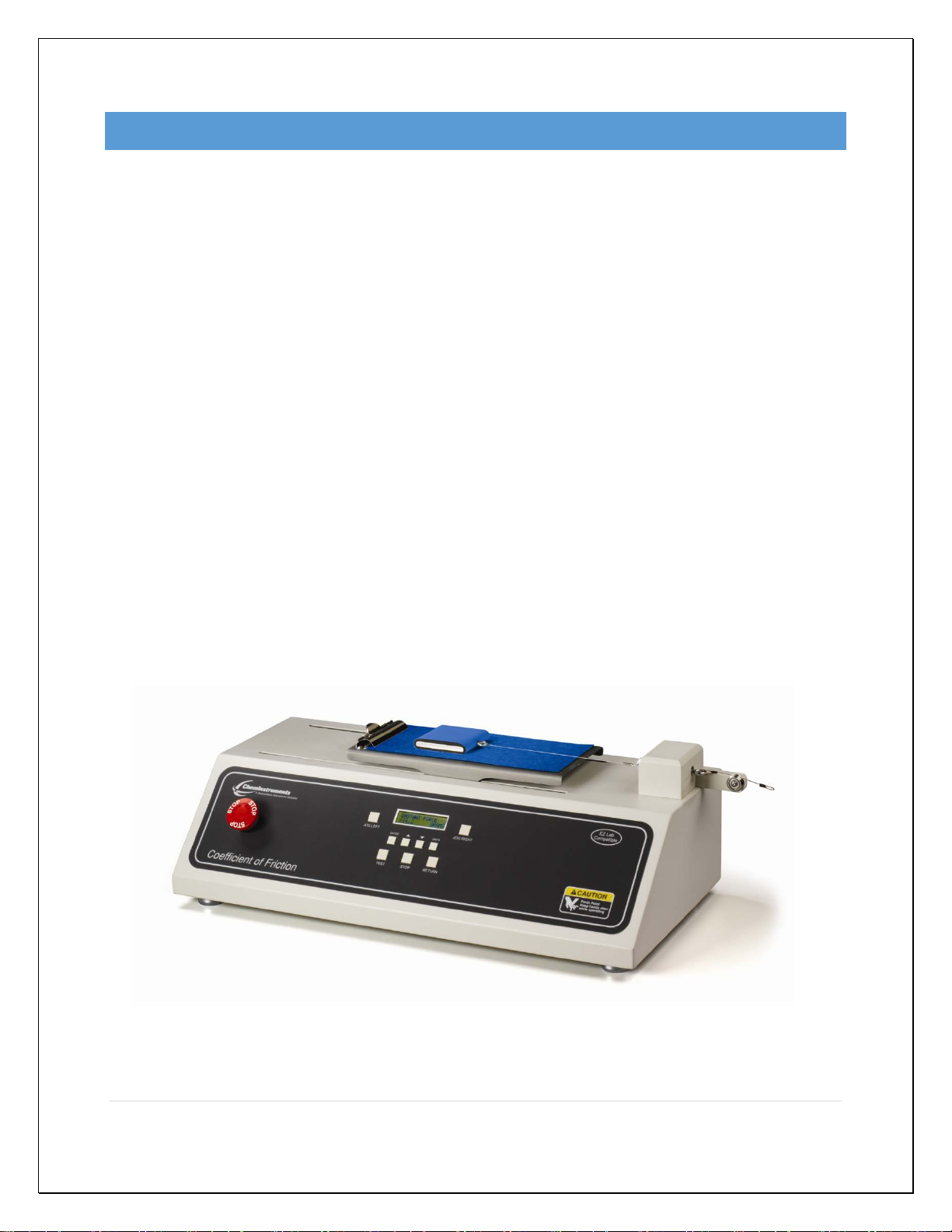
PRODUCT DESCRIPTION
Congratulations on the purchase of your new ChemInstruments COF-1000, Coefficient
of Friction Tester. This versatile, user-friendly, carefully designed instrument allows you
to determine coefficient of friction values of many different materials according to many
test methods including ASTM D-1894.
WARNING: This equipment can cause injury if not used properly. It is
the operator’s responsibility to observe all safety rules and warnings.
The unit has the following features:
•Internal load cell (standard 5 pound) accurate to 0.1% of full scale.
•One step test sequence.
•Small enough to fit on a desktop.
•Collected test data can be exported via RS232 port.
•Selectable units of measure: Kilograms, Grams, Newtons, Pounds, & Ounces.
•Compatible with EZ-Lab System software. See www.cheminstruments.com for
details.
SPECIFICATIONS
Electrical
120/240 VAC, 50/60 Hz, 2 amps
Operating
Temperature
32 – 150 degrees Fahrenheit (0 – 70 degrees Celsius)
Speed
6, 12, 24 inches per minute (15, 30, 60 centimeters per minute)
Sled Mass
1 – 2000 grams
Physical
Dimensions Width: 23 inches (58 centimeters)
Depth: 12 inches (30 centimeters)
Height: 8 inches (20 centimeters)
Weight: 29 pounds (13 kilograms)
3 | Page
Coefficient of Friction Tester Operating Instructions (COF-1000)
UNPACKING
ChemInstruments has made every effort to ensure that the COF-1000 arrives at your
location without damage. Carefully unpack the instrument and check for any damage
that may have occurred during shipment. If any damage did occur during transit, notify
the carrier immediately.
The ChemInstruments COF-1000 consists of the following parts:
•Coefficient of Friction tester.
•An envelope with this manual.
•Test Sled with connecting cable.
•Calibration cable (attached).
•Power cord.
Make sure all of these components are present before discarding packaging material.
4 | Page
Coefficient of Friction Tester Operating Instructions (COF-1000)
ASSEMBLY
Carefully remove the test frame/data acquisition assembly from the packaging and set it
on a sturdy bench top. Check the physical dimensions listed previously for the space
required for the instrument. As with any precision piece of laboratory equipment, it is
preferable to locate the COF-1000 in an area where temperature and humidity are
controlled to standard conditions of 72 ± 2 degrees Fahrenheit and 50 ± 5% relative
humidity.
WARNING: Make sure the power source matches the requirements of the
Coefficient of Friction Tester. Damage will occur if this unit is plugged
into the incorrect power supply.
Level the COF-1000 tester by adjusting the four leveling feet located at each corner of
the unit.
Place the Test Sled on the Test Platform and connect the cable to the hook on the Load
Cell.
Connect the power cord to its receptacle on the backside of the control cabinet.
Complete the connection by inserting the male end of the power cord into an
appropriate AC outlet. Notice that the on/off power switch is located directly beside the
power cord receptacle on the backside of the test frame.
WARNING: Before proceeding with using the COF-1000, it is advisable
to become familiar with the Key Components. These Key Components
and a brief description of their function follow in the next section.
5 | Page
Coefficient of Friction Tester Operating Instructions (COF-1000)

KEY COMPONENTS
•POWER SWITCH is located on the back panel of the COF tester at the lower left
hand side.
•TEST SLED consists of a foam rubber wrapped 200 gram platform that slides
across the Test Platform.
•LOAD CELL measures the forces involved with a COF test.
•CALIBRATION CABLE & PULLEY consist of a cable connected to the load cell and
threaded over the pulley to allow you to hang a weight during the calibration
sequence
•E-STOP emergency stop button
•DIGITAL DISPLAY provides test data results and system status information.
•CONTROL BUTTONS consist of 9 buttons (Jog Left, Jog Right, Enter, Up Arrow,
Down Arrow, Units, Test, Stop, & Return) for control of the test sequence and other
machine functions.
Load Cell
Calibration
Pulley & Cable
Test Platform
Control
Buttons
E-Stop
Digital Display
Test Sled
6 | Page
Coefficient of Friction Tester Operating Instructions (COF-1000)

THEORY OF OPERATION
The Test Platform moves at a constant speed causing friction between itself and the
stationary Test Sled. An electronic load cell measures the force, then feeds the
information to a data acquisition unit. The data acquisition unit collects the data from
the load cell and stores these data points in memory for use in calculating the
maximum, minimum and average values. The forces generated during the test are also
used in calculating the Static COF and Kinetic COF of the test material.
POWER UP
Turn on the master power switch located on the back panel of the control cabinet next
to the power line receptacle.
WARNING: Operating temperature for this equipment is 32 to 150
degrees Fahrenheit (0 to 70 degrees Celsius). The equipment needs to be
completely free of condensation, inside and out, before applying power.
MACHINE SETUP
LOAD CELL CALIBRATION
It is important to calibrate the load cell to ensure that reliable data will be gathered. A
calibration procedure is built into the software of the COF-1000. This procedure should
be followed upon first use of the COF-1000 and whenever necessary thereafter. The
following is the step-by-step procedure for calibrating the load cell.
Make sure that the COF-1000 has been powered on for 30 minutes before
proceeding with calibration.
7 | Page
Coefficient of Friction Tester Operating Instructions (COF-1000)

The calibration sequence defaults to grams as the unit of measure. Make
sure that your calibration weights and entries are in grams.
LOAD CELL CALIBRATION PROCEDURE
1. Simultaneously press the Up and Down Arrow keys for 3 seconds to access the
Setup mode.
2. Use the Up Arrow key to cycle to “Load Cell Setup” on the display.Press the
Enter button.
3. At the “LO CAL” display, determine the Low Offset Value desired (typically 0.00).
Make sure that you do not have a weight hanging, and press the Enter key. The
display will change to “HI CAL” for high calibration value.
4. At the “HI CAL” display select a calibration weight close to the maximum
expected test value. Hang that weight using the calibration cable and pulley.
5. Set the High Offset Value on the Display to correspond with the selected
calibration weight. You can change the displayed value by pressing the Up and
Down Arrow keys.
6. Verify that the hanging weight is completely at rest without any movement. Press
the Enter key to complete calibration.The display will change to the “INSTANT
FORCE” mode showing the current reading of force.
7. Verify the calibration by hanging a different calibration weight. Confirm that
the instantaneous force reading is the same as the selected weight hanging on
the calibration wire and pulley.
8 | Page
Coefficient of Friction Tester Operating Instructions (COF-1000)

8. Repeat the calibration procedure if necessary.
9 | Page
Coefficient of Friction Tester Operating Instructions (COF-1000)

UNITS OF MEASURE
Use the UNITS button to change the units of measure for the force reading. Pressing
the UNITS button will cycle the units from Grams, Kilograms, Ounces, Pounds, and
Newtons.
CURRENT FORCE READING
A current force reading is available by accessing the “INSTANT FORCE” mode. To
access this mode, simply press the Up Arrow button until the display shows “INSTANT
FORCE”. The second line of the display will be the current force being measured with
the selected units. This reading should be used only as a quick reference.
NOTE: It is important to remember that the load cell is measuring forces at a rate
of 400 times per second. The rate of display on the display screen cannot cycle
at this speed. Therefore, the value in the “INSTANT FORCE” reading is an
average of the data points that the load cell is measuring.
SPEED SETUP
The test platform can be set to travel at any one of three different speeds. The following
procedure describes how to set the test platform speed.
1. Press both the Up and Down Arrow keys together for 3 seconds to enter the
Setup Mode.
2. Use the Up Arrow key to cycle the display to “Speed Setup”.
3. Press the Enter key.
4. Press the Up Arrow key to cycle from 6, 12, to 24 inches per minute (15, 30, to
60 centimeters per minute).
5. Press the Enter key to record your speed selection. The display will return to the
“INSTANT FORCE” reading.
10 | Page
Coefficient of Friction Tester Operating Instructions (COF-1000)

SLED MASS SETUP
The weight of the Test Sled is used in the calculation that determines the Static COF
and Kinetic COF.The following procedure describes how to enter the sled mass.
1. Press both the Up and Down Arrow keys together for 3 seconds to enter the
Setup Mode.
2. Use the Up or Down Arrow key to cycle the Display to “Sled Mass Setup”.
3. Press the Enter key.
4. Press the Up or Down Arrow key to change the Test Sled weight value.
Remember that this value is displayed in grams.
5. Press the Enter key to record your selection.
RUNNING A TEST
Make sure the load cell has been calibrated before conducting a test.
TEST PROCEDURE
The following procedure will describe a normal test sequence for the COF-1000 tester.
1. Attach your sample material to both the Test Sled and Test Platform according to
the appropriate test method.
2. Place the Test Sled on the center of the Test Platform and as far left as the
connecting cable will allow.
3. Position the Test Sled so that the edges of the Test Sled are parallel to the edge
of the Test Platform.
4. Adjust the position so that the cable has enough slack for it to rest on the Test
Platform. The Instant Force reading should be below 5 grams at this point.
11 | Page
Coefficient of Friction Tester Operating Instructions (COF-1000)
WARNING: Before proceeding, make sure there is nothing in the path of
the test platform.
5. Push the Test key on the control panel.
6. Wait for the test platform to come to a complete stop.
7. The internal computer will calculate the Static and Kinetic COF results.
8. The display will default to the average value. Other values are accessed by
pushing the Up or Down Arrow keys.
WARNING: Make sure the Test Sled is removed from the path of the
Test Platform before pushing the Return button
9. Pushing the Return key will return the test platform to the start position for the
next test.
COF TEST DESCRIPTION AND RESULTS
The COF moves at a constant speed causing friction between itself and the stationary
test sled. The forces generated during the test are measured and used in calculating
the Static COF and the Kinetic COF of the test material.
STATIC
The first part of the test is the static part. This will consist of 100 data points, which is 2
seconds of data. The peak value during this part of the test is saved and displayed in
the EZ Lab graph as “First Peak”. The Static COF value is defined as follows:
12 | Page
Coefficient of Friction Tester Operating Instructions (COF-1000)

= ( )
( )
KINETIC
The second part of the test will collect the following number of data points dependent on
speed:
1. 3000 data points if speed equals 6 in/min or 15 cm/min
2. 1500 data points if speed equals 12 in/min or 30 cm/min
3. 750 data points if speed equals 24 in/min or 60 cm/min
The average, high, and low values are calculated from this part of the test and displayed
on the graph screen in EZ Lab. The Kinetic COF value is defined as follows:
= ( )
( )
13 | Page
Coefficient of Friction Tester Operating Instructions (COF-1000)

MAINTENANCE
TROUBLESHOOTING
The troubleshooting chart describes some problems that may occur over time. After
determining the problem, follow one of the following maintenance procedures.
Troubleshooting Chart
Problem
Possible Cause
Procedure
No data collected Display is in SETUP screen Go to MAIN screen to run a
test
Test platform does not
move during a test
Motor is not allowing the
assembly to move
Replace motor or drive
Data measurement
consistently low/high Improper calibration
Check calibration
Bad calibration
Refer to load cell calibration
Calibration drifts
Bad or damaged load cell
Replace load cell
MAINTENANCE PROCEDURES
As with any precision equipment it is important to provide care and maintenance to
ensure proper performance and long life. General cleaning and care will ensure
accurate test and trouble free performance.
14 | Page
Coefficient of Friction Tester Operating Instructions (COF-1000)
Table of contents
Other ChemInstruments Test Equipment manuals


