Electro-Sensors SA420 User manual
ENT
SA420
OUT%
VAR RATE
Description:
Electro-Sensor’s SA420 Signal Conditioner provides an analog signal
directly proportional to the speed of a monitored shaft. The 0-10 VDC
and 4-20 mA outputs can be sent to a chart recorder, digital display, PLC,
loop controller, drive speed controller, or other control or monitoring
devices. The wide voltage range and wave shape exibility of the
SA420’s sensor input circuitry allow it to translate signals from Hall-
Eect Sensors, proximity switches, magnetic sensors, and a wide variety
of other pulse generator devices into analog outputs.
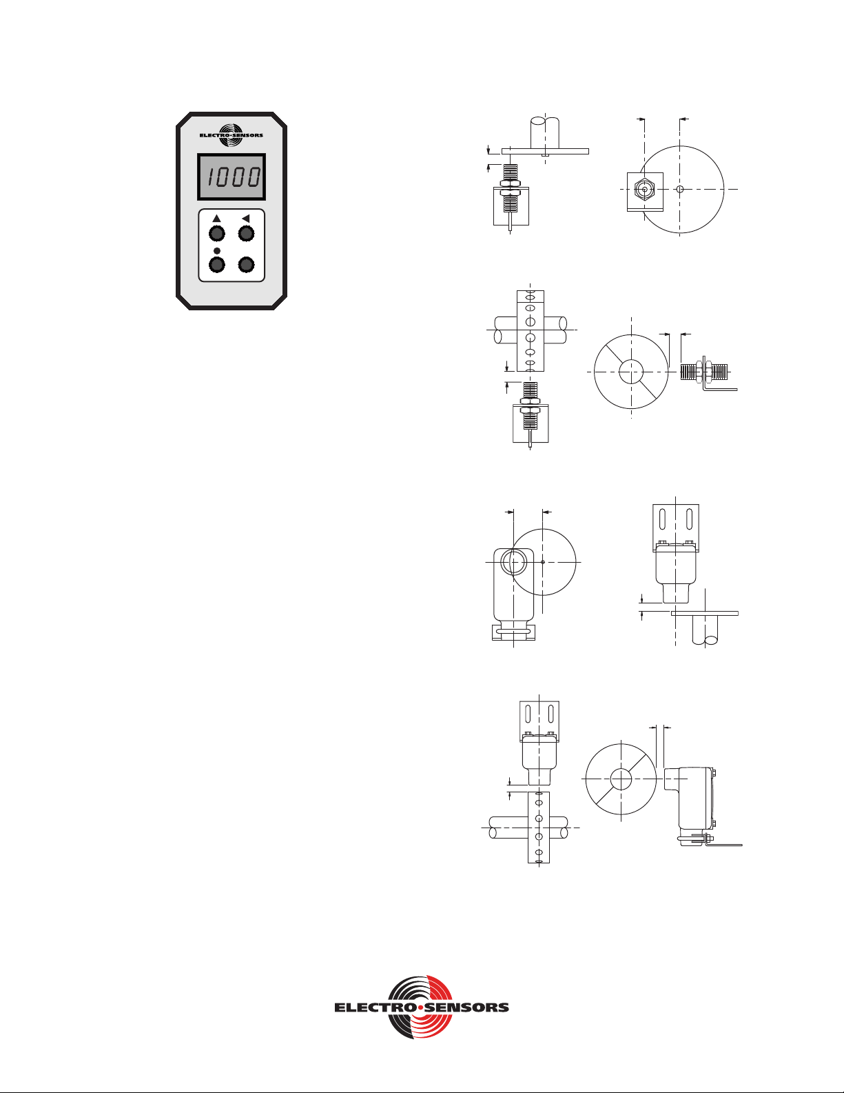
Sensor Installation:
The standard sensor is supplied with a mounting bracket and two jam
nuts. The explosion-proof sensor is supplied with a slotted mounting
bracket. Sensors should be installed so the centerline of the magnets
pass in front of the center of the sensor as the disc or wrap rotates. When
using the pulser disc, the center of the magnetized area of the disc,
shown as Dimension B in gures 1 and 3, is 1-3/4 inches from the center
hole of the disc. The gap distance between the sensor and the disc or
wrap, Dimension A In the diagrams, is 1/4-inch ±1/8 inch. To achieve
the proper gap distance, adjust the jam nuts holding the standard sensor
in the mounting bracket, or adjust the position of the explosion-proof
sensor using the slots on its mounting bracket.
Pulser Disc:
The end of the shaft to be monitored must be center drilled to a depth of
1/2-inch with a No. 21 drill and tapped for 10-32UNF. After applying
Loctite™ or a similar adhesive on the threads to keep the pulser disc
tight, the pulser disc should be attached, decal side out, with the supplied
10-32UNF machine screw and lock washer.
Pulser Wrap (optional):
Pulser Wraps are custom manufactured to t the shaft they will be
mounted on. When the wrap is shipped, four Allen-head cap screws hold
the two halves of the wrap together. These screws must be removed so
that the wrap is in two halves. Place the halves around the shaft, reinsert
the screws and torque them to 5 foot-pounds max.
A
B
Figure 1: Standard Sensor with 255 Pulser Disc
A
A
Figure 2: Standard Sensor with optional Pulser Wrap
B
A
Figure 3: Explosionproof Sensor with 255 Pulser Disc
A
A
Figure 4: Explosionproof Sensor with Pulser Wrap
SA420 Signal Conditioner
6111 Blue Circle Drive
Minnetonka, MN 55343
Phone: 952.930.0100
Fax: 952.930.0130
ISO 9001:2015 Certied
Free Catalog and Application Assistance
1.800.328.6170
Visit Us Online
www.electro-sensors.com
990-001700 Revision I

SA420 Signal conditioner
For version 3 hardware with version 5.xx or later rmware
The SA420 now includes the following features:
• Quadrature (directional decoding)
• Bipolar voltage output (units now include +/- 5 VDC and +/- 10 VDC)
• Optional higher NPN input signal trip point (improves operation through IS barrier)
• Programmable lower analog output setpoint (Previously xed at 0 Hz, now includes forward and reverse osets) PR (00)
• Programmed to power up and display in the following units PR (04):
• Hz (default)
• Percent of maximum output
• User dened units
• Programmable minimum frequency cuto. PR (05) (This allows you to decide where the unit zeroes out for faster zeroing)
• More modes of operation:
• Single channel
• Quadrature 1X
• Single channel 2X (new)
• Quadrature 2X (new)
• Quadrature 4X (new)
• Security lock variables (viewable but not changeable while locked)
• Ability to improve calibration with user variables which alter the upper and lower calibration point of the analog
• Choice of new menu or revert to basic 3 variable menu for compatibility
Free Catalog and Application Assistance
1.800.328.6170
Website: www.electro-sensors.com
990-001700 Revision I
2-8

Wiring Connections:
Sensor Wire connections:
Terminal
Model
906/
Old 907
All other
ESI
Sensors
Mag
Pickup
Logic
Level
ESI
Prox/
New 907
5 Supply Red Red N/C N/C Brown
6 Signal Black Clear + Signal Black
7 Ground Clr/Shd Blk/Shd - Common Blue
11 Signal B Green Green N/C N/C White
Power Connections:
Terminal 115 VAC
Standard
230 VAC
Optional
12 VDC
Optional
24 VDC
Optional
2 Hot L1 Hot (+)Positive (+)Positive
10 Neutral L2 Hot (-)Negative (-)Negative
Analog Output Connections:
Terminal 4-20 mA Terminal 0-10 VDC
3(+) High 9 (+) Positive
4 (-) Low 8 (-) Negative
Terminal Connection
8
765
4
9
1110 12
3
1No Connect
2 Hot +
34-20mA +
4 4-20mA -
5 Sensor Supply
6Sensor Signal A
7 Sensor Ground
80-10 VDC -
90-10 VDC +
10 Neutral -
11 Sensor Signal B
Figure 5: Terminal Block wiring
Frequency Calculations
Pertinent formula: Frequency (Hz) = (RPM * PPR)/60
Example: A customer has a motor rotating at 1200 RPM and wants the
SA420 to output 20mA at 1250 RPM using a Hall Eect sensor and an
ESI 255 disc.
Since the Hall Eect sensors turns on with a south eld and o with a
north eld, the 255 disc’s 16 alternating magnets (8 north and 8 south
elds) will produce 8 PPR (Pulses Per Revolution). Insert 8 into the
equation for PPR.
F = (1250 * 8)/ 60
F = 166.7 Hz [Value used in PR (01)]
Programming:
There are four buttons on the front panel used for calibration:
▲ Up Arrow Button is used to change the value of the position in focus
(ashing), while in the calibration mode. While in standard mode, this
button will toggle the display between frequency input (hertz) and output
percentage.
◄ Left arrow button is used to move the focus to the next position when
in the calibration mode of 4-20 mA or 0-10 VDC.
•Decimal Point Button is used to change the position of the decimal
point while in the calibration mode.
ENT Enter Button is used to enter or exit the calibration mode.
Programming The Unit:
Standard menu: To enter the calibration mode, push the ENT button
once. PR0 will be displayed. Press the ▲ (up) button to increment to
the desired variable. Press the ENT button at which time the value
of variable is displayed. The right most digit of the variable will be
ashing, which indicates that this digit has the focus and can be changed.
Pressing the ▲ (up) button will increment the ashing digit. The ◄
button will advance the focus to the next digit to be changed. The •
(DP) button will scroll the decimal point across the display from right
to left if that variable has the decimal point enabled. When the correct
value is programmed into the variable, press the ENT button to store the
variables value in memory. The display will show PRxx (the variable
you just updated). You can now ▲ (up) button to the next variable you
wish to change or continue until you’ve reached the end of variables and
exit to user mode.
Basic menu: To enter the calibration mode, push the ENT button once.
PR1 will be displayed for one second, and then the value of variable
1 is displayed. This is the Max frequency value. the right most digit
of variable 1 will be ashing, which indicates that this digit has the
focus and can be changed. Pressing the ▲ button will increment the
ashing digit. The ◄ button will advance the focus to the next digit to
be changed. The • (DP) button will scroll the decimal point across the
display from right to left. When the correct value is programmed into
the variable, press the ENT button to store the variable into memory and
access variable Pr02. Pr02 is the sensor type. You can now change Pr02
to match the sensor output type if necessary or press the ENT button and
advance to Pr03. Pr03 contains the input pulse buer. When the value
is correct press the ENT button to save value and to return to the user
mode.
ENT
SA420
OUT%
VAR RATE
Free Catalog and Application Assistance
1.800.328.6170
Website: www.electro-sensors.com
990-001700 Revision I
3-8

Variable functions
PR (00) Analog Lower Setpoint*
Setpoint for 4mA and 0 VDC value. (-5 or -10VDC if selected). To
represent a reverse rate, increment the left most digit until the rate icon
ashes. **
PR (01) Analog Upper Setpoint*
Setpoint for 20mA and 10 VDC value. (5 VDC or 10 VDC if selected).
To represent a reverse rate, increment the left most digit until the rate
icon ashes. **
PR (02) Sensor Type and Level
Used to select your sensor output type. The default is set to 0.
Variable 2 Value Type of Sensors
0NPN*
1PNP
2 Magnetic Pickup
3Logic Level
4NPN 6.5V
5PNP 6.5V
*(All Standard ESI sensors are NPN open collector output.)
PR (03) Buer Size
Ring buer ltering up to 600 pulses. It is a rst-in-rst-out
conguration. Typically, you would put in the PPR of the sensor/target
combination or a supermultiple of the PPR.
Example: Customer using 906 sensor (Hall type with 1 PPR per 2
magnets) and a 255 disc (16 alternating magnets) would generate 8PPR.
Normally you would use 8, 16, 24, 32… for the buer size. Using higher
counts makes the output more stable but slows the response down. You
need to strike a balance between buer size and response.
PR (04) User Units
Value to be displayed when operating at PR (01) frequency. (FPM, RPM,
etc.) this is the value to display when operating at the frequency entered
in variable Pr01.
PR (05) Frequency Cuto
User can set the frequency cuto to zero the unit faster. Customers that
are reading higher speeds may want to raise the value entered here to
quickly zero the unit out. conversely customers that need to read lower
speeds may want to reduce this number, so it doesn’t zero out too soon.
PR (06) Analog Response
Some applications need slower analog response rates. This variable is
where you set the time required to slew from 10-90% analog output
PR (07) Signal Type**
Programming of PR (07) determines the way the signals are handled.
There are multiple choices for both single and quadrature operation. 1X
uses the rising edge of channel “A”. 2X uses the rising and falling edge
of channel “A”. the quadrature 4X uses both the rising and falling edges
of both the “A” and “B” channels. When using 2X or 4X congurations
the PPR calculations will be double or quadruple verses the 1X
conguration and the user needs to increase the Pr01 (Analog upper
setpoint) value upward accordingly.
PR (08) Voltage Output Type
Controls the type of voltage output from the unit. There are multiple
options see the table in the variable table on page 6.
PR (09) Menu Option
Controls what program menu is used. User can choice between the
current advanced menu or revert for compatibility to the basic menu
which has three variables.
All units will start in the new advanced menu unless the user programs
it to use the basic menu. A user can get it back to the advanced menu
which is the standard menu now by: holding down the decimal button
and left arrow button simultaneously while powering on the unit. Then
change PR (09) from (0000) to (0001) and press enter. The advanced
menu will remain afterwards when restarting the unit.
Keep in mind that advanced features will be retained if you switch from
the advanced menu back to the basic menu until you reset the unit. If you
change PR (09) to zero (0000) the variables will remain but only PR (01)
through PR (03) will be viewable.
PR (10) Display Option
User can set how the feedback is displayed. This enables the display of
user to set in user units
PR (11 thru 14) Reserved
PR (15) Security PIN
To advance past this point when going through the menu this PIN must
match the password. This will make the variable Read/Write rather than
read only.
Free Catalog and Application Assistance
1.800.328.6170
Website: www.electro-sensors.com
990-001700 Revision I
4-8

PR (16) Security Password
User can lock variables. Making PR (15) dierent from PR (16) will lock
the variables and make PR (16) unviewable. It is important to remember
the number entered in PR (16).
PR (17) Cal: PIN
To advance past this point when going through the menu this PIN must
match the password. This will make the Cal variables accessible.
PR (18) CAL: Password
User can update variables 10-22 if the Cal pin matches the Cal password.
Making PR (17) dierent from PR (18) will lock the calibration variables
and make PR (18) unviewable. It is important to remember the number
entered in PR (18).
PR (19) CAL: Voltage oset value
Setting that allows the user to adjust the Voltage oset to obtain greater
accuracy.
Not implemented yet
PR (20) CAL: Voltage gain value
Setting that allows the user to adjust the Voltage gain to obtain greater
accuracy.
Not implemented yet
PR (21) Cal: Current oset value (4.000mA)
Setting PR21 allows the user to adjust the current oset to obtain greater
accuracy. The adjustment value is approximately 366nA (0.000366uA)
of deviation up or down per single count of change. Example
of changing this from 1000 to 980 results in the analog decreasing. It
will decrease (20 *0.000366uA) or -0.00732uA. When done after the
initial warm up of the unit, about 15 minutes, it can dramatically increase
the accuracy of the unit.
PR (22) Cal: Current gain value (20.000mA)
Setting Pr22 allows the user to adjust the current gain value to obtain
greater accuracy. The adjustment value is approximately 366nA
(0.000366uA) of deviation up or down per single count of change.
Example: Changing this value from 1000 to 1010 will result in the
analog output increasing. It will increase (10 * 0.000366uA) or
0.00366uA. When done after the initial warm up of the unit, about 15
minutes, it can dramatically increase the accuracy of the unit.
*Users can program the analog to go up or down as the frequency
increases by swapping the lower setpoint [PR (01)] with their upper
setpoint [PR (00)].
**Reverse numbers are represented by a ashing “rate” icon and cannot
be programmed until PR (07) is set for quadrature operation.
Free Catalog and Application Assistance
1.800.328.6170
Website: www.electro-sensors.com
990-001700 Revision I
5-8

SA420 Advanced Mode Variables
Variable Number and Name Default
Value
Value
Range
Coded Number Table Move
Decimal
User Values
(00) ANALOG_LOWER_SP_VAR 0any number * Yes
(01) ANALOG_UPPER_SP_VAR 240.0 any number * Yes
(02) SENSOR_TYPE_VAR 0000 0-5 0 = NPN (2.5 VDC trip level)
1 = PNP (2.5 VDC trip level)
2 = Mag (75 mVDC trip level)
3 = Logic (2.5 VDC trip level)
4 = NPN (6 VDC trip level)**
5 = PNP (6 VDC trip level)**
No
(03) BUFFER_SIZE_VAR 8 0-16 No
(04) USER_UNITS_VAR 1800 any number * Yes
(05) FREQUENCY_CUTOFF_VAR 0.5 0.0-10.0 Hz No
(06) ANALOG_RESPONSE_VAR 00.00 00.00-20.00 Amount of time it takes the analog
output to change from 10% to 90%
Examples:
00.00 or 00.01 = 00.01 seconds
00.10 = 0.10 seconds
00.50 = 00.50 seconds
No
(07) SIGNAL_TYPE_VAR 0 0-4 0 = Single channel operation
1 = Quadrature operation
2 = Single channel 2X operation
3 = Quadrature operation 2X
4 = Quadrature operation 4X
No
(08) VOLTAGE_OUTPUT_TYPE VAR 10-3 0 = 0-5 VDC
1 = 0-10 VDC
2 = +/- 5 VDC
3 = +/- 10 VDC
No
(09) MENU_OPTION_VAR 1 0-1 0 = Basic menu
1 = Advanced menu (Standard)
No
(10) DISPLAY_OPTION_VAR 0 0-2 0 = Hz
1 = Percent output
2 = User units
No
(11) reserved for future use
(12) reserved for future use
(13) reserved for future use
(14) reserved for future use
No
(15) SECUR_PIN_VAR 0420 0000-9999 No
(16) SECUR_PASS_VAR 0420 0000-9999 No
(17) SECUR_CAL_PIN_VAR 0 0000-9999 No
(18) SECUR_CAL_PASS_VAR 0420 0000-9999 No
(19) CAL: VOLTAGE_OFFSET 1000 0000-2000 Currently not active No
(20) CAL: VOLTAGE_GAIN 1000 0000-2000 Currently not active No
(21) CAL: CURRENT_OFFSET 1000 0000-2000 No
(22) CAL: CURRENT_GAIN 1000 0000-2000 No
* When the ‘rate’ icon is ashing, the number being programmed is a reverse direction value. A value can only be displayed as a reverse direction
value AFTER the unit is programmed to operate in quadrature mode. This prevents errant reverse values from being entered into a single-channel
unit.
** Recommended quadrature setting for NPN or PNP.
Free Catalog and Application Assistance
1.800.328.6170
Website: www.electro-sensors.com
990-001700 Revision I
6-8

SA420 Dimensional Drawings:
Dimensions in Inches
3.00
5.63
2.28
1.75
1.66
Figure 6: SA-420
2.28
1.18
1.34
0.85
1.44
6-32
1.66
Figure 7: Terminal Block
4.00
0.196
0.250
Figure 8: 255 Pulser Disc
2.00"
2.51"
2.00"
2.00"
1.25"
1.00"
1.00"
1.120"
Figure 9: Standard Sensor
2.38
5.53
1.16
3.38
1.00
1" NPT
1.63
3.75
1.88
Nut &
Lockwasher
0.56
1.25
4.63
Figure 10: Explosionproof Sensor
1.00
.43
0.13
2
.75 1.63
.32
.56
2.88
1.25
2.03.39
0.33
Figure 11: Explosionproof Sensor Bracket
Free Catalog and Application Assistance
1.800.328.6170
Website: www.electro-sensors.com
990-001700 Revision I
7-8
Troubleshooting Guide
Problem Possible Solution
Unit Dead Check for proper supply at
terminals 2 and 10. See gure 5 on
page 3
No Analog out with zero
hertz displayed
Check for Sensor supply. It should
be Approximately 13.6 VDC
Check sensor Gap distance
Check Sensor Type (Variable 2)
Unit displays a
frequency but the analog
is incorrect
Check variable 1 for correct
frequency
Check your on the correct
analog output, voltage(VDC) or
current(mA)
Analog is unstable Check gap distance
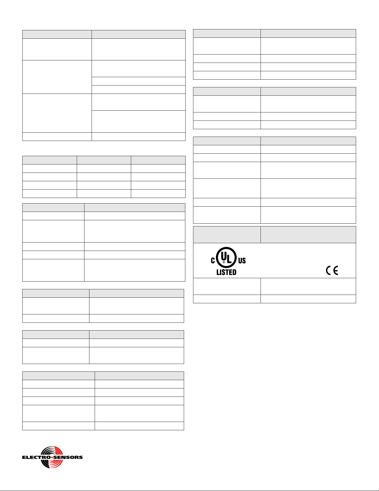
SA420 General Specications:
Input Power Input Current Fuse Type (F2)
115 Vac, 60Hz (std) 2.5 VA Sloblo .032A 5X20
230 Vac, 60Hz (opt) 2.5 VA Sloblo .032A 5X20
12 Vdc (opt) 165 mA Sloblo .250A 5X20
24 Vdc (opt) 135 mA Sloblo .200A 5X20
Input Signal Parameters
Sensor Supply 12 VDC (unregulated) @50 mA max.
Programmable Types
Open collector NPN / PNP
Logic Level 5 V Nom. 3 V Min.
Magnetic Sensor +/- 75 MV Min.
Max. Amplitude 25 Vpk-pk Maximum
Frequency Range 0.01 Hz to 10 kHz
Minimum Input for
Full Scale Output
0.5 Hz = 3.8 RPM @ 8 PPR
(Lower full scale range is available,
consult Factory)
Analog Output Signal Parameters
Types 0 - 10 VDC, 4 - 20 mA with 500Ω
load max.
Accuracy (typical) 0.1% Linearity for both outputs
Step Response Time Parameters
50 Hz Input and above 10 to 90% = 50 ms.
Below 50 Hz Input 10 to 90% = 30 ms + 1/Hz Input
frequency
Physical/Envlronment Parameters
Mounting DIN rail mount or Stand alone
Operating temperature 0°C to +60°Cz
Storage temperature -65°C to +125°C
Electrical Connections 11 Position DIN rail terminal
block
DIN rail enclosure rating NEMA 1
Free Catalog and Application Assistance
1.800.328.6170
Website: www.electro-sensors.com
990-001700 Revision I
8-8
255 Pulser Disc (std.) Parameters **
Material Nylon 12 Std,
(opt; PVC, Alum, Stainless-Steel)
Dimensions 4-inch diameter x 1/4-inch thick
Operating Temperature -40ºC to +60ºC* (Nylon, PVC)
Operating Temperature -40ºC to +150ºC* (Alum, SS)
Pulser Wrap (optional) Parameters **
Material PVC Std.
(opt; Aluminum or Stainless-Steel)
Operating Temperature -40ºC to +60ºC* (PVC)
Operating Temperature -40ºC to +150ºC* (Aluminum, SS)
906 Sensor (Standard) Parameters **
Material Sensor Body Aluminum 3/4 - 16UNF thread
Material Mount Bracket Plate steel
Output Types NPN open collector current sinking
20 mA max
Signal Cable 3-conductor shielded, 10 feet length
std. (50 ft. or 100 ft. optional)
Operating Temperature -40ºC to + 60ºC*
Air Gap 1/4 inch +/- 1/8 inch with standard
255 Pulser disc (1/2” magnets)
907 Explosionproof
Sensor (optional)
Parameters **
Class I, Div 1, Group D
Class II, Div 1, Groups E, F, G
UL File: E249019
Mounting Bracket
Material
Plate Steel U-Bolt Assembly
Other Specications Similar to 906 standard sensor
Specications are subject to change without notice.
*For higher or lower temperature ranges, consult factory.
** For details on Discs, Wraps and Sensors, consult factory
or visit our website.
Table of contents
Popular Test Equipment manuals by other brands


Extech Instruments
Extech Instruments TK36 owner's guide

Amptec Research
Amptec Research 620A 4R Operation and maintenance manual

ACE INSTRUMENTS
ACE INSTRUMENTS WAVE operating manual

DeFelsko
DeFelsko PosiTector SST instruction manual

VOLTCRAFT
VOLTCRAFT VC64 operating instructions

IDEAL INDUSTRIES
IDEAL INDUSTRIES OTDR Technical manual