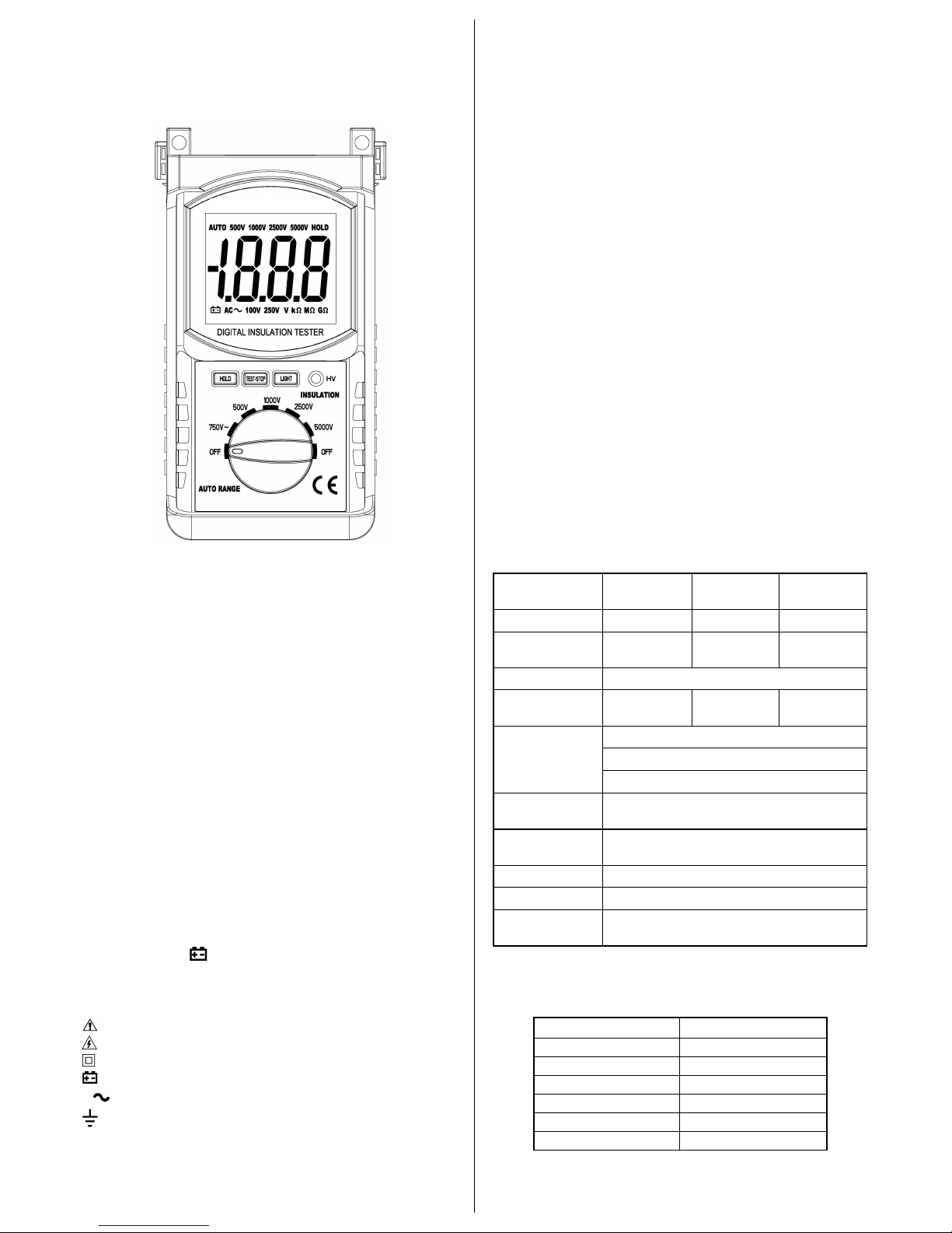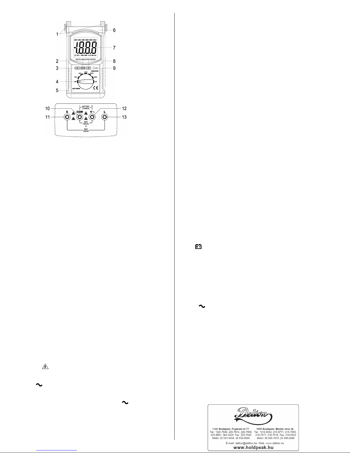
(2) High voltage startup switch: TEST/STOP
(3) Data holding key: HOLD
(4) Rating voltage rotating switch
(8) Back light switch: LIGHT
(9) High voltage indicator light
(10) ACV measurement terminal COM
/ Shield input terminal for insulation
/ Battery charge negative pole
(11) EARTH input terminal (Insulation)
/ Battery charge positive pole
(13) LINE input terminal (Insulation)
7. Operating specification
a. There is a possibility of causing an accident of electric shock.
After the measurement of insulation resistance is completed, be
sure to discharge the high voltage charged in the measuring
b. There is a risk of electric shock during the measurement. Be
careful not to touch the measuring terminal and measuring object
c. When the circuit is activated, make measurement after
disconnecting the power source.
d. Make measurement within the insulation resistance
measuring range, and never impress voltage from outside, or the
tester will be destroyed.
e. Be sure to confirm the position of rotary switch and the
connection of measuring lead with the tester before starting the
f. When start the high voltage startup switch, there is a high
voltage about 100V ~5000V between Land E, must not touch
the bare part of meet and object be tested cause of the danger of
a. Don’t test up AC 750V voltage. It is Dangerous!
b. Connect the measuring Leads
Insert the red plug of lead with probe to measuring terminal
“V”, and the black plug of AC measuring lead to measuring
terminal “COM”, respectively.
c. Connect to the measuring object
Using the rotary switch select the “750V ” position. Connect
the test pin of lead with probe to the other side of measuring
object, and the test pin of AC measuring lead to another part of
d. Then the digital display voltage is the AC voltage of the
(3) Insulation resistance testing
a. Connection of measuring lead
Insert the big plug of lead with probe to measuring terminal “L”,
the plug of lead with clip to measuring terminal “E”, and the black
plug of AC measuring lead with a small clip to measuring terminal
b. Testing lead connected
The lead with the big measuring clip is the leads connected with
the earth. The lead with the high voltage’s probe is the
highest-voltage leads. The lead with connecting in “COM” socket
is the shield leads meeting on the surface of the testing resource
to preventing the surface leak affecting testing resistance. Using
the rotary switch select the “OFF” position, connect the clip of
lead to the other side of measuring object, and the AC measuring
lead’s small clip to the surface of measuring object.
Select the Rating Voltage adapt to the insulation resistance you
Turn the rotating switch to the voltage segment needed.
Connect the probe to object, press the button “TEST/STOP”,
“HV” indicator light, which indicates measuring voltage happen.
After testing begins, the number displayed on LCD is the
insulation value of object tested.
After the measurement completed, push down the switch of the
“TEST/STOP” once more .When the red LED off, means the
output testing high voltage has been cut. Turn the rotary switch to
“OFF” position. If measure the contain nature load, please short
the residually electric of the testing resource first before move the
On any range, press the “HOLD” key to lock display value, and
the “HOLD” sign will appear on the display, press it again to exit.
On any range, press the “LIGHT” key to light the back light. The
light can wink automatically after approx. 10 seconds.
8. Battery replacement (or battery charge)
1) When the battery voltage drop below proper operation range,
the “ ” symbol will appear on the LCD display and the
battery need to changed (or charge the battery by the charger).
2) Before changing the battery (or charge the battery by the
charger), set the selector switch to “OFF” position.
3) Open the cover of the battery cabinet by a screwdriver.
4) Replace the old battery with the same type battery.
5) Close the battery cabinet cover and fasten the screw.
6) When charge the battery by the charger, set the selector
switch to “OFF” position, then connect the black plug of the
charger to the "COM" socket and the red plug of the charger to
7) Connect the charger to the AC power (AC 110V or 220V), the
light of the charger will flicker red, it means the battery is
charging. The light of the charger will light green when the
battery be charged full, then please stop charge.
Caution: Dispose the used batteries according to the rules,
which are defined by each community.
This is a precise instrument and needs careful maintenance.
a. Don’t open the back lid at will. Don’t use it if the back lib not
b. Put it in the place dry and airiness if the meter will be leave
c. Don’t change the inner circuit at will or the meter maybe out of