Macmesin MultiTest-xt Instruction Manual

Assembly and Installation of
MultiTest–xt and Vortex-xt
System Test Stands
431-388-08
September 2015

ii Mecmesin Assembly and Installation of –xt System Test Stands
Important
It is essential that you familiarise yourself with the contents of this Assembly and
Installation Manual, and the separate Guide to Safe Use of Mains Powered Test Systems
before attempting to operate your MultiTest-xt or Vortex-xt Test System.
Warranty
The -xt console is pre-configured at Mecmesin for use with the MultiTest-xt and Vortex-xt
stands. With the exception of the Advanced Builder Option, which requires a
configuration change to the console, any unauthorised changes to the console
configuration and set-up will invalidate the warranty.
The 24-month end-user warranty for the console itself is with a third party. Please contact
your local Mecmesin agent for assistance with this warranty.
The Microsoft® Windows® Embedded operating system is pre-installed and licensed by
Mecmesin and supplied with an End User License Agreement, and Certificate of
Authenticity.
Scope
This reference manual covers the following products and their derivatives: (example)
Force testing stands
Single
-column stands MultiTest 0.5-xt
MultiTest 1-xt
MultiTest 2.5-xt
MultiTest 5-xt
Twin
-column stands MultiTest 10-xt
MultiTest 25-xt
MultiTest 50-xt
Torque testing stand
Vortex–xt Torque cell capacities:
0.3, 1.5, 3, 6, 10 Nm
2015 © Mecmesin Ltd, supplied with Mecmesin test systems and not for redistribution
Part no. 431-388-08

Assembly and Installation of –xt System Test Stands Mecmesin iii
Contents
1. Items Supplied with the Test Stand 1
1.1 MultiTest-xt test stand 1
1.2 Vortex-xt test stand 1
2. Installation 2
2.1 Unpacking the stand 2
2.2 Lifting the test stand 2
2.3 Locating the stand 2
2.4 Mains power supply 2
3. MultiTest-xt Assembly and Installation 2
3.1 Bolting the test stand to the work surface 3
3.2 Fitting the feet to the stand 4
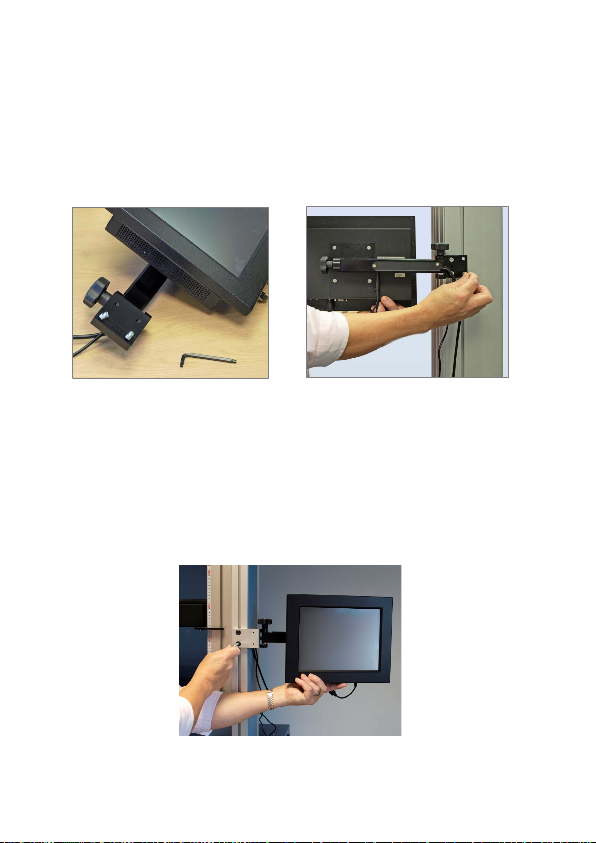
3.3 Fitting the console to a single column test stand 4
3.4 Fitting the console to a twin-column stand 5
3.4.1 Twin column stands with guards 6
3.5 Fitting the loadcell to the crosshead 7
3.6 Swapping loadcells 8
3.7 Attaching grips and fixtures 8
3.8 Setting the limit stops 9
4. Vortex-xt Assembly and Installation 11
4.1 Fitting the console to the Vortex-xt 11
4.2 Fitting the crosshead to the Vortex-xt 11
4.3 Connecting the intelligent torque cell 12
4.4 Swapping intelligent torque cells 13
5. Connecting the Console (MultiTest-xt and Vortex-xt) 14
5.1 Connecting the console power lead and USB lead 14
5.2 Switching on the system 14
5.3 Connecting other devices 15
5.4 Emergency stop button 15
5.5 Jog buttons 15
5.6 The touch screen console 15
5.7 Operators and Master users 16

iv Mecmesin Assembly and Installation of –xt System Test Stands
System Specifications 18Appendix A
EC Declarations of Conformance 21Appendix B
Microsoft® Windows® Embedded Standard 7 Licensing 23Appendix C
End User License Agreement (EULA) 23
Certificate of Authentication (COA) 23

Assembly and Installation of –xt System Test Stands Mecmesin 1
1. Items Supplied with the Test Stand
1.1 MultiTest-xt test stand
1. Test stand
2. Console fitted with arm, power cable and USB cable
3. Tools to fit the console to the test stand
4. CD with software and manuals for backing up or running on a PC
5. Assembly and Installation guide (this manual)
6. Translation of ‘A Guide to the Safe Use of Mains Powered Test Frames’ (does not
apply to English speaking countries, or countries outside European Union)
7. Adjustable handle lever to secure loadcell to crosshead
8. Appropriate mains cables for test stand and console
9. Allen keys and Torx wrenches
10. Four rubber feet, four attachment screws and Allen key (if applicable)
11. Four base anchoring brackets, (if applicable)
12. Adaptors (if applicable)
1.2 Vortex-xt test stand
1. Test stand
2. Console fitted with arm, power cable and USB cable
3. Intelligent Torque Cell (ITC), as an integral part of the crosshead
4. CD with software and manuals for backing up or running on a PC
5. Start-up guide
6. Translation of ‘A Guide to the Safe Use of Mains Powered Test Frames’ (does not
apply to English speaking countries, or countries outside European Union)
7. Appropriate mains cables for test stand and console
8. Allen keys and Torx wrenches

2 Mecmesin Assembly and Installation of –xt System Test Stands
2. Installation
2.1 Unpacking the stand
When you first receive the stand please check that there is no obvious damage to the
packaging. If there is any sign that the packaging or the test stand itself has been
damaged, please contact Mecmesin or your authorised distributor immediately. Do not
use the stand until you have done so.
We strongly recommend that the packaging is kept, as this can be useful if the machine
needs to be returned for calibration.
Section 1 lists items that should be included with your test stand. Please contact
Mecmesin or your authorised distributor if any items are missing or damaged.
2.2 Lifting the test stand
The unpackaged weight of the test stand is given in the Specification table at the back of
this manual. Do not try to lift heavy loads unaided. Use suitable lifting equipment if
necessary.
2.3 Locating the stand
The test stand should be positioned on a suitable, level, stable work surface.
2.4 Mains power supply
Mecmesin –xt stands can be used on 110–120 or 220–240 V ac 50-60 Hz supplies. The rear
fuse carrier will be set for your local requirement, but is reversible, so should you replace
a fuse, the correct local voltage must be selected. The voltage that is selected is the one
where the arrows meet (the power inlet is inverted for some test stands):
Fuse carrier Carrier removal

Assembly and Installation of –xt System Test Stands Mecmesin 3
3. MultiTest-xt Assembly and Installation
3.1 Bolting the test stand to the work surface
In order to comply with European regulation and safe use of the equipment, single
column stands should be secured to the bench as follows:
Test stand Height (mm) Feet/fixing supplied Bolting recommended?
0.5-xt 1710 Anchor brackets Yes
1-xt 1510 Anchor brackets Yes
2.5-xt 941 Rubber feet No*
5-xt 1082 Rubber feet /locating eyes Yes
* For MultiTest-xt console-controlled frames we recommend that the console is located below the information
label on the mounting rail for stability. If the console is to be mounted above this point, please contact your
authorised Mecmesin agent to purchase a set of anchor brackets.
The extended-length test stands MultiTest 0.5-xt and MultiTest 1-xt are supplied with
base anchoring brackets to allow the test stands to be bolted to a bench. Screw the
anchoring brackets to the four positions on the base plate of the MultiTest 0.5-xt or 1-xt
using the M6 screws provided. Secure the test stand to the bench using suitable
fastenings.
MultiTest 0.5-xt and 1-xt are supplied with anchoring brackets

4 Mecmesin Assembly and Installation of –xt System Test Stands
For additional stability the MultiTest 5-xt is fitted with two ‘locating eyes’ on the base of
the MultiTest 5-xt to allow the stand to be bolted to a bench.
Locating eyes on MultiTest 5-xt
Mecmesin twin-column force testing stands and Vortex torque testing stands require no
further stability fixing than a flat, secure and stable working surface.
3.2 Fitting the feet to the stand
Fitting rubber feet to the base of the test Stand
The MultiTest 2.5-xt and MultiTest 5-xt are supplied with rubber feet. Support the stand
and fit the four rubber feet to the base of the stand.
3.3 Fitting the console to a single column test stand
The console is supplied assembled onto a mounting bracket. This needs to be attached to
the side of the stand with the supplied tamper-resistant Torx screws, and the appropriate
Torx wrench is provided. Note: Do not use any other tools other than those provided.
From the back of the stand, identify the short sliding bar held in place in the vertical slot
that runs the length of the column. This has two screw holes for the console bracket and a

Assembly and Installation of –xt System Test Stands Mecmesin 5
central grub screw for adjusting vertical height. Then identify the two console bracket
holes and fit the upper screw.
Support the console with one hand and, with the top screw held in place by the supplied
Torx wrench, locate the bracket on the sliding bar and engage the screw. When almost
tight, fit the lower screw. Tighten both and release the console. Height can now be
adjusted by slackening the grub screw through the hole between the fixing screws whilst
supporting the console, as shown, then re-tightening at the required height. The
maximum recommended height is 700 mm (27.6”). Note: Do not exceed the
recommended height as this can cause problems with the stability of the test stand.
The sliding bar with central grub screw Fix the upper Torx screw first
Using the Allen (hex) key, adjust the console height Use the two knobs to adjust tilt and swing
The angle and rotation of the console are locked into set positions by sprung pins. Slacken
the appropriate knob and reposition the bracket or arm on alternative pin locations.
3.4 Fitting the console to a twin-column stand
Consoles for a twin-column stand are supplied assembled onto a mounting bracket with
an extended mounting plate for attaching to the slot running down the rear of the right-
hand column. The plate is fitted with two Torx screws and flat ‘T’-shaped nuts, as shown

6 Mecmesin Assembly and Installation of –xt System Test Stands
below. This needs to be attached to the slot using the supplied Torx wrench. Note: Do no
use any other tools other than those provided.
Slacken the two nuts off and align then vertically to fit into the slot. Support the console
with one hand and, with the top screw held in place by the Torx wrench, locate the
bracket over the slot and engage the screw. This will rotate the ‘T’ nut and engage in the
slot. When almost tight, turn the lower screw. Tighten both and release the console.
Height can now be adjusted by supporting the console and slightly slackening the nuts to
move the console up or down.
Twin column mounting plate and tool Fit the ‘T’ nuts into the rear slot and tighten
The angle and rotation of the console are locked into set positions by sprung pins. Slacken
the appropriate knob and reposition the bracket or arm on alternative pin locations, as
shown above for single column stand assembly.
3.4.1 Twin column stands with guards
Where a twin column stand is fitted with a guard cabinet, the console may be fitted to the
frame. A mounting plate will be already fitted; secure the console bracket to the rear of
the plate using the two screws provided. Height may be adjusted by slackening the
mounting plate screws slightly, and retightening at the appropriate height.
Supporting the console, slacken the screws and adjust the height.

Assembly and Installation of –xt System Test Stands Mecmesin 7
3.5 Fitting the loadcell to the crosshead
Single-column stands
Ensure the stand is switched off.
Screw the adjustable handle lever with the red button into the crosshead dovetail. This
lever is designed to tighten without full rotation. Hold the button on the top to raise and
disengage the lever, and turn it away from the direction required. Release and turn, and
repeat as required.
Do not tighten the lever without a loadcell attached, or the dovetail can become
distorted.
Inserting the adjustable handle lever
On single-column test stands, slide the loadcell (ILC) sideways onto the dovetail bracket at
the front of the crosshead. The threaded stud must always be on the underside. Secure the
loadcell using the handle lever. Some lateral adjustment is available if needed to align the
ILC and a sample. Slacken the lever to make the adjustment, and then re-tighten.
Note: There is some additional adjustment available by moving the anvil plate. Use a
3 mm Allen key to slacken the four retaining screws, reposition the anvil plate and re-
tighten the screws.
Align the electrical connector of the ILC with the socket on the test stand. Gently push the
connector to locate, then tighten the knurled locking ring in a clockwise direction.
Slide the loadcell onto the dovetail … tighten securely … connect the loadcell

8 Mecmesin Assembly and Installation of –xt System Test Stands
Twin-column stands
The ILC is attached to a twin-column test stand using a cap-head bolt passed through the
central hole in the moving crosshead, and secured using the Allen key provided.
Attaching a loadcell on a twin-column system
3.6 Swapping loadcells
You can swap loadcells by simply disconnecting one cell and fitting another. First, return
to the Main Screen and switch off the stand before unplugging the loadcell. When the
new loadcell has been connected, switch the stand on again, and after a few seconds the
new loadcell will be automatically recognised. The MultiTest-xt will read in the new cell’s
range, serial number and calibration status.
3.7 Attaching grips and fixtures
Grips and other holding fixtures are often paired, with one being attached to the anvil
plate, and the other to the underside of the loadcell. Some fixtures have the QC Quick-
interchange system which allows for very rapid changing of the holding accessory.
Attaching a grip with the QC Quick Interchange fittings

Assembly and Installation of –xt System Test Stands Mecmesin 9
With the Quick-interchange system, the grip is attached to a mounting using an 8 mm
diameter pin. The grip can be fitted and removed without the need for additional tools.
Be sure to fit the locking spring to secure the accessory in place.
Take extra care when fitting or removing heavy grips to the underside of the loadcell.
Support the accessory while the securing device is removed so that it does not fall. Before
fitting a sample, check that both grips and plates are secure.
3.8 Setting the limit stops
Limit stops are provided to prevent damage to the loadcell and grips. A dual safety
system provides protection with the first stage being software controlled, followed, if
necessary, by a second hardware limit that removes power from the motor. Upper and
lower limit stops can be set to restrict movement of the crosshead. If the crosshead
reaches a limit during a test, it will stop then reverse direction for approximately 5 mm,
then stop again. A warning message is displayed on the touch screen:
Press OK to acknowledge the warning and use the Jog buttons to move the crosshead so
that you can then check the position of the limit stops and re-set if required.
If a limit stop is reached while pressing one of the Jog buttons on the front panel of the
MultiTest-i, a different warning message is displayed.
Pressing OK will allow you to correct the situation and continue.
Pressing Abort will disconnect the stand from the console, and display the following
message:
Press OK then Exit to go to the Front Screen, this will reconnect the stand again.
Limit stops should be adjusted after grips or holding accessories have been fitted so that
the limit positions will prevent unwanted contact between moving and static parts. To set
either limit stop, slacken the knurled knob by turning it anti-clockwise, then slide the stop
to the desired position and re-tighten the knob again.

10 Mecmesin Assembly and Installation of –xt System Test Stands
Remember to check and, if necessary, adjust the position of the limit stops if the grips are
exchanged for a different holding accessory.
Limit stops on a MultiTest 1-xt. Stops on other stands all operate in the same way.
Twin-column stands have system limit stops as well as limit stops. System limit stops
should not be moved. In an emergency, to release a trapped sample the system limit can
be moved, but if you do so, you must contact your Mecmesin distributor for servicing
and re-setting. These stops are designed for protection from damage, and moving them
may affect your warranty on the stand.
Lower limit stop and system limit stop on a twin-column stand
upper and lower
limit stops
The crosshead will stop when
it reaches this position
Lower limit stop
System limit stop

Assembly and Installation of –xt System Test Stands Mecmesin 11
4. Vortex-xt Assembly and Installation
4.1 Fitting the console to the Vortex-xt
Using the Allen key supplied, fit the stand bracket to the right-hand column as shown,
and adjust the height. The console is supplied assembled onto a mounting bracket. This
needs to be attached to the stand bracket with the two supplied security screws, and the
Torx wrench provided. Note: Do no use any other tools other than those provided.
Support the console with one hand and, with the top screw held in place by the supplied
Torx wrench, locate the console on the stand and engage the screw. When almost tight, fit
the lower screw. Tighten both and release the console.
Fit and adjust height of the bracket Attach the console to the bracket
The angle and rotation of the console are locked into set positions by sprung pins. Slacken
the appropriate knob and reposition the bracket or arm on alternative pin locations, as
shown above for single column stand assembly.
4.2 Fitting the crosshead to the Vortex-xt
Slide the crosshead onto the two support columns and tighten both securing thumb-screws.
Different height samples can be accommodated by moving the complete crosshead up
and down. Additional adjustment is available by moving the top-load carrier.

12 Mecmesin Assembly and Installation of –xt System Test Stands
If a top-load is to be used, the securing knob is generally left undone during
measurement so the carrier can slide up and down. If a top load is not to be used,
securely tighten the locking knob after adjusting to the height required.
Crosshead fitted to Vortex-xt with top-load weights in the carrier
4.3 Connecting the intelligent torque cell
Align the electrical connector of the ITC with the mating socket on the test stand. Gently
push the connector to locate then tighten the knurled locking ring in a clockwise
direction.

Assembly and Installation of –xt System Test Stands Mecmesin 13
4.4 Swapping intelligent torque cells
You can swap the torque cell by simply disconnecting one cell, removing the crosshead
and then fitting another. First, return to the front screen and switch off the stand before
unplugging the torque cell. When the new torque cell has been connected, switch the
stand on again, and after a few seconds the new torque cell will be automatically
recognised. The console will read in the new cell’s range, serial number and calibration
status.
ITC connector

14 Mecmesin Assembly and Installation of –xt System Test Stands
5. Connecting the Console
(MultiTest-xt and Vortex-xt)
5.1 Connecting the console power lead and USB lead
The console is powered from a separate universal supply plugged into a mains socket.
Caution: use only the mains adaptor supplied by Mecmesin, do not use any other type.
The power lead and USB lead will already be connected—check that they are firmly fitted
to the console. Plug the power adaptor into a suitable socket. Plug the USB cable into the
9-way socket labelled ‘PC’ on the rear of the Vortex or single-column MultiTest stand, or
the right hand side of a twin-column MultiTest stand. Normally it will not be necessary to
remove the USB cable, but should this be required, return the console to the front screen
display before removing the USB connector.
Rear panels of a Vortex-xt (left) and MultiTest-xt (right). Plug the USB cable into the circled PC socket.
5.2 Switching on the system
Switch on the test stand using the main switch located on the rear on Vortex or single-
column MultiTest stands, or on the right hand side of twin-column MultiTest stands. On
all systems, four green power lights (LEDs) on the front panel will illuminate.
Switch the touch screen console on by pressing the small button switch located on the
underside of the console (shown below) to the right of the power lead. After a few
seconds the splash screen will be displayed.
on/off switch
power in
USB sockets
network
comms

Assembly and Installation of –xt System Test Stands Mecmesin 15
5.3 Connecting other devices
Connect printers or other device using the spare USB sockets on the console underside.
5.4 Emergency stop button
The emergency stop button will stop all movement of the crosshead. Pushing the button
will override all other controls. When pressed, the button stays latched down, preventing
any movement of the MultiTest crosshead or the Vortex platen. To re-set the button,
rotate it about 30 degrees clockwise.
The front panel of the MultiTest 1-xt. Vortex-xt has a similar
emergency stop button and clockwise and anticlockwise jog buttons.
5.5 Jog buttons
Jog buttons are used to position the crosshead so that samples can be attached to the
grips. -xt Test Stands have a pair of jog buttons on the stand, and another pair on the Live
Test Run screen. The two sets of buttons function in different ways.
Stand jog buttons speed Touch screen jog buttons speed
Quick Test Factory set fixed rate Jog speed increments or decrements
each time the jog button is pressed
Program Test Factory set fixed rate Rate set in Program test set-up > Test
Settings
Advanced Test Factory set fixed rate Rate as set in Set-up > Preferences
5.6 The touch screen console
The touch screen is used to control the -xt system. Please note that this Windows
computer does not contain an internal battery. If power to the system is interrupted,
unsaved data will be lost.
Emergency stop
Jog buttons

16 Mecmesin Assembly and Installation of –xt System Test Stands
You can select operations and options by pressing or tapping on the relevant button on
the touch screen with a finger or a stylus. In the bottom right of any screen layout
requiring typed entry, there is a keyboard icon. Touch this, and a floating keyboard
appears so you can type in numbers or text. If this obscures an entry field, just drag it out
of the way. Where a layout has no data entry, the keyboard will automatically slide out of
sight to the left, but it does not appear automatically when data may be required. Simply
tap the keyboard icon whenever you need it.
The –xt console showing the floating keyboard icon bottom right, and keyboard
•a single tap or press is the same as a left mouse button
•press-and-hold is the same as a right mouse button
•a double-tap is a double-click
•touch and drag a finger to select text
•combination keys such as Shift+ and Ctrl+ are used sequentially. For example, to select
contents of a field, press Ctrl and then A. To copy, press Ctrl and then C. To paste,
press Ctrl and then V.
•touch and drag a window element by its title bar—such as the floating keyboard itself.
5.7 Operators and Master users
Both the MultiTest-xt and Vortex-xt have been designed to be very simple to use. There
are two levels of user, and a password is used to restrict access to either a simple choice of
pre-defined tests or some limited functions, or access to the full capabilities of
the -xt system.
Operators can select from tests that are pre-defined, and for which reports have already
been written, and some functions that can be assigned to each user account. For more
details see your manual: Emperor Programming for Mecmesin xt Test Systems.
keyboard
keyboard icon
This manual suits for next models
1
Table of contents
Popular Test Equipment manuals by other brands

Martindale Electric
Martindale Electric BZ701 instruction manual

Bender
Bender UNIMET 1000ST operating manual

Phase 2
Phase 2 SRG-4600 Operation manual

Teledyne Lecroy
Teledyne Lecroy frontline TLF 3000 user manual

Agilent Technologies
Agilent Technologies 2000 X-Series Service guide

Klein Tools
Klein Tools NCVT-1XT instructions