Chemtronics MDRBI303 User manual
CHEMTRONICS
Motion Detection Sensor Module
User Manual
Product Name
Motion Detection Sensor Module
Model Name
MDRBI303
Version
0.1
Date
October 27, 2021

Revision History
Version
Date
Description
0.1
October 27, 2021
Draft Version

Contents
1. Overview................................................................................................................................................................................ 4
2. System Specification.......................................................................................................................................................... 5
2.1 Physical feature................................................................................................................................................................... 5
2.3 Pin Description.................................................................................................................................................................... 6
2.4 Module Specification......................................................................................................................................................... 7
2.5 RF Specification................................................................................................................................................................. 9
3. Module Assembly.............................................................................................................................................................10

1. Overview
This product is a module developed for effective human or object recognition using the built-in RADAR
sensor. The core functionality of this radar sensor is to transmit frequency modulated continuous wave
(FMCW) signal via one of the transmitter channel (TX) and receive the echo signals from the target object on
the three receiving channels (RX).
The Color sensor is a high resolution color and IR(red, green, blue, clear and IR) light sensor which can
transform illuminance(light intensity) to a digital signal output. With the RGB color sensor, the brightness and
color temperature of backlight can be adjusted based on ambient light source that makes the panel look more
comfortable for human eyes. Additionally it can be used for detecting light source type as it reports the IR
content of the light. The wide dynamic range also allows for operation in short distance detection behind dark
glass such as a cell phone.
The IR Receiver are miniaturized receiver for infrared remote control system. The Pin Photodiode and
preamplifier are assembled on lead frame. The epoxy package is designed as IR filter. and this IR Receiver has
excellent performance even in disturbed ambient light application and provides.
The microphone mounted on top of the product is a compact low power bottom port silicone microphone with
a single bit PDM output. This device has great performance and is suitable for applications such as music
recorders and other suitable electronic devices.
The accelerometer is a process micromachine accelerometer that has already been used in production in
rugged and mature manufacturing belonging to the "femto" family of ultra-low-power, high-performance 3-
axis linear accelerometers.
Features
◼RF-Frontend at 60 GHz covering frequencies from 58.0 to 63.5 GHz with one TX and three RX
channels
◼Antennas integrated in the redistribution layers of the package
◼CW and FMCW mode of operation
◼Color(R,G,B,W,IR) Sensor with I2C Interface
◼D-MIC(DOS3527B-R26-NXF1)
◼receiver for infrared remote control system.
◼Micro-machine accelerometer belonging to the "femto" family.
◼80MHz Oscillator
Applications
◼Smart TV appliances
The Motion Detection Sensor Module specified is a product that is installed in the application after
being mounted on the frame in actual use.
2. System Specification
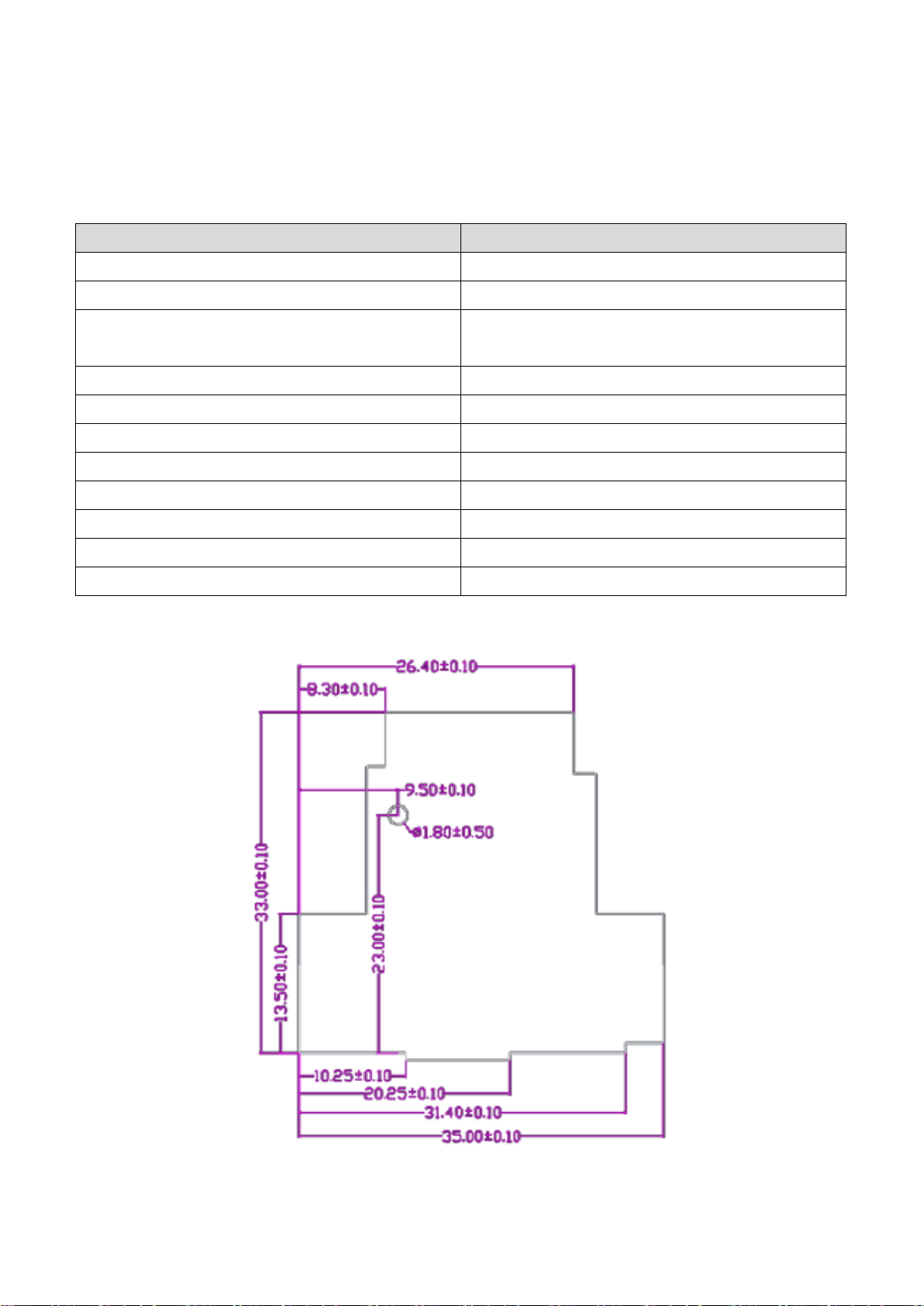
2.1 Physical feature
Item
Specification
Product Name
Motion Detection Sensor Module
Model Name
MDRBI303
Communication method
RF-Frontend at 60 GHz covering frequencies from 58.0 to
63.5 GHz
Dimension
35mm x 33mm x 1.4mm(T)
Weight
2.78g
Mounting Type
FFC Connector(24Pin Header), Screw(1Hole)
Function
Acceleration Sensor, MIC, Color Sensor, IR Receiver
Mutual of the person being certified
CHEMTRONICS Co., Ltd
Manufacturer/country of manufacture
CHEMTRONICS Co., Ltd / Korea
Date of manufacture
Marked separately
Certification Number
-
2.3 Pin Description
Pin
No.
Pin Name
Type
Function
Pin
No.
Pin Name
Type
Function
1
IR_RX
I
IR Signal Receive
2
HOST_SPI_INT
I/O
MCU_SPI_INTERRUPT
3
RADAR_I2C_SCL
I/O
RADAR_I2C_SCL
4
RADAR_I2C_SDA
I/O
RADAR_I2C_SDA
5
HOST_WAKEUP
I/O
MCU_WAKEUP
6
HOST_NRESET
I/O
MCU _RESET
7
GND1
P
Digital Ground
8
HOST_SPI_CS
I/O
MCU_SPI_Chip Select
9
HOST_SPI_SCLK
I/O
MCU_SPI_CLK
10
HOST_SPI_MISO
I/O
MCU_SPI_MISO
11
HOST_SPI_MOSI
I/O
MCU_SPI_MOSI
12
GND2
P
Digital Ground
13
SENSOR_I2C_SDA
I/O
SENSOR_I2C_SDA
14
SENSOR_I2C_SCL
I/O
SENSOR_I2C_SCL
15
GND3
P
Digital Ground
16
LED_IND
P
RED LED Control
17
KEY_INPUT_1
I
TACT KEY INPUT
18
MIC_SWITCH
I/O
MIC_ Power Control
19
GND4
P
Digital Ground
20
MIC_DATA
I/O
MIC_I2C_SDA
21
MIC_CLK
I/O
MIC_I2C_CLK
22
GND5
P
Digital Ground
23
TP_5V_PW
P
INPUT 5V
24
D_3.3_PW
P
INPUT 3.3V

2.4 Module Specification
2.4.1 Product Summary
Item
P/N
Description
Radar IC
BGT60TR13C
- The core functionality : transmit FMCW
MCU
CY8C6244LQI-S4D92
- ultra-low-power and secure MCU platform, purpose-built
for IoT applications
LDO
TMI6030 –18
NCP163AMX330TBG
NCP163AMX180TBG
- Excellent Transient Response
- Low Quiescent Current
- Ultra Low Noise
- Ultra High PSRR
OSC
O.PD.DTHVFAF0080000000
- Low Frequency Tolerance
- Low Phase Noise
MIC
DOS3527B-R26-NXF1
- High SNR
- High Sensitivity
- Low output Impedance
ACCELERATION
SENSOR
LIS2DWLTR
- Very low noise: down to 1.3 mg RMS in low power Mode
- supply voltage, 1.62 V to 3.6 V
- High-speed I2C/SPI digital output interface
Color Sensor
AL8844
-i2c interface
-Detect R,G,B,W,IR colors
IR RECEIVER
ROM-SA138MFH-R
- Internal Pull-Up output.
- Lead(Pb)-free component
SLIDE S/W
JS6901EM
- This specification is applied to low current circuit slide
switch for electronic equipment.
TACT S/W
DHT-1187AC
-
RED-LED
LTST-C191KRKT
- lightweight makes them ideal for miniature applications.
2.4.2 Electrical Specification
Parameter
Description
Min.
Typ.
Max.
Units
Supply Voltage(3.3V)
2.97
-
3.63
V
Operating Current(5V)
RMS
60
mA
Supply Voltage(5V)
4.5
-
5.5
V
Operating Current(5V)
RMS
-
-
60
mA
2.4.3 Environment Specification
Item
Specification
Storage Temperature
-25℃ to + 115℃
Operating Temperature
-10℃ to + 80℃
Humidity (Operational)
85%(50℃) relative humidity
Vibration (Operational)
5 Hz to 500 Hz sinusoidal, 1.0G
Drop
No damages after 75cm drop over concrete floor
ESD [Electrostatic discharge]
+/- 0.8 kV Human Body Model (JESD22-A114-B)
2.5 RF Specification
2.5.1 RF FE Characteristics
Parameter
Condition
Min.
Typ.
Max.
Units
Frequency Range
61.02
61.25
61.48
GHz
Transmit Output Power
Conductive Power
1.0
4.0
8.0
dBm
Output Power Variation over
Temperature
For Tx DAC set to #31
-2.0
+2.0
dB
Transmitter Power Control Dynamic
Range
15
dB
DAC Resolution Transmitter Power
Control
By design
5
Bits
Receiver Conversion Gain
12
14
16
dB
Conversion Gain Variation Over
Temperature
Including the
Complete baseband chain
-3
+3
dB
Receiver Single Sideband Noise Figure
@100kHz offset
12
14
dB
Receiver 1-dB Compression Point
-10
-5
dBm
Channel-to-Channel RX Isolation
40
dB
LO feedthrough at the RX port
-30
dBm
TX-to-RX Isolation
50
dB

3. Module Assembly
Be careful not to damage the module when you assemble or disassemble. If you press heavily RADAR IC, it
may affect the overall performance.
※Screw: CA+ B D:2.5 H:0.5 C:0.15; 1.7*2.5*3 CR+3 WH

FCC MODULAR APPROVAL INFORMATION EXAMPLES for Manual
This device complies with Part 15 of the FCC Rules. Operation is subject to the following two conditions:
(1) This device may not cause harmful interference.
(2) This device must accept any interference received, including interference that may cause undesired
operation.
CAUTION: Changes or modifications not expressly approved by the party responsible for
compliance could void the user's authority to operate the equipment.
NOTE: This equipment has been tested and found to comply with the limits for a Class B digital device,
pursuant to Part 15 of the FCC Rules. These limits are designed to provide reasonable protection against
harmful interference in a residential installation. This equipment generates uses and can radiate radio
frequency energy and, if not installed and used in accordance with the instructions, may cause harmful
interference to radio communications. However, there is no guarantee that interference will not occur in a
particular installation. If this equipment does cause harmful interference to radio or television reception,
which can be determined by turning the equipment off and on, the user is encouraged to try to correct the
interference by one or more of the following measures:
- Reorient or relocate the receiving antenna.
- Increase the separation between the equipment and receiver.
- Connect the equipment into an outlet on a circuit different from that to which the receiver is connected.
- Consult the dealer or an experienced radio/TV technician for help.
FCC Radiation Exposure Statement:
This equipment complies with FCC radiation exposure limits set forth for an uncontrolled environment. This
equipment should be installed and operated with minimum distance 20cm between the radiator & your
body.

OEM INTEGRATION INSTRUCTIONS:
This device is intended only for OEM integrators under the following conditions:
The module must be installed in the host equipment such that 20 cm is maintained between the antenna
and users, and the transmitter module may not be co-located with any other transmitter or antenna. The
module shall be only used with the internal on-board antenna that has been originally tested and certified
with this module. External antennas are not supported. As long as these 3 conditions above are met, further
transmitter test will not be required.
However, the OEM integrator is still responsible for testing their end-product for any additional compliance
requirements required with this module installed (for example, digital device emissions, PC peripheral
requirements, etc.). The end-product may need Verification testing, Declaration of Conformity testing, a
Permissive Class II Change or new Certification. Please involve a FCC certification specialist in order to
determine what will be exactly applicable for the end-product.
Validity of using the module certification:
In the event that these conditions cannot be met (for example certain laptop configurations or co-location
with another transmitter), then the FCC authorization for this module in combination with the host
equipment is no longer considered valid and the FCC ID of the module cannot be used on the final product.
In these circumstances, the OEM integrator will be responsible for re-evaluating the end product (including
the transmitter) and obtaining a separate FCC authorization. In such cases, please involve a FCC certification
specialist in order to determine if a Permissive Class II Change or new Certification is required.
Upgrade Firmware:
The software provided for firmware upgrade will not be capable to affect any RF parameters as certified for
the FCC for this module, in order to prevent compliance issues.
End product labeling:
This transmitter module is authorized only for use in device where the antenna may be installed such that 20
cm may be maintained between the antenna and users. The final end product must be labeled in a visible
area with the following: “Contains FCC ID: A3LMDRBI303”. Information that
must be placed in the end user manual:
The OEM integrator has to be aware not to provide information to the end user regarding how to install or
remove this RF module in the user's manual of the end product which integrates this module. The end user
manual shall include all required regulatory information/warning as show in this manual.

FCC MODULAR APPROVAL INFORMATION EXAMPLES for Manual
This device complies with Part 15 of the FCC Rules. Operation is subject to the following two conditions:
(1) This device may not cause harmful interference.
(2) This device must accept any interference received, including interference that may cause undesired
operation.
CAUTION: Changes or modifications not expressly approved by the party responsible for
compliance could void the user's authority to operate the equipment.
NOTE: This equipment has been tested and found to comply with the limits for a Class B digital device,
pursuant to Part 15 of the FCC Rules. These limits are designed to provide reasonable protection against
harmful interference in a residential installation. This equipment generates uses and can radiate radio
frequency energy and, if not installed and used in accordance with the instructions, may cause harmful
interference to radio communications. However, there is no guarantee that interference will not occur in a
particular installation. If this equipment does cause harmful interference to radio or television reception,
which can be determined by turning the equipment off and on, the user is encouraged to try to correct the
interference by one or more of the following measures:
- Reorient or relocate the receiving antenna.
- Increase the separation between the equipment and receiver.
- Connect the equipment into an outlet on a circuit different from that to which the receiver is connected.
- Consult the dealer or an experienced radio/TV technician for help.
WARNING
Changes or modifications not expressly approved by the manufacturer could void the user’s authority to
operate the equipment.
“CAUTION : Exposure to Radio Frequency Radiation.
Antenna shall be mounted in such a manner to minimize the potential for human contact during normal
operation. The antenna should not be contacted during operation to avoid the possibility of exceeding the
FCC radio frequency exposure limit.

IC Information
This device complies with Industry Canada license-exempt RSS standard(s). Operation is subject to the
following two conditions:
(1) this device may not cause interference, and
(2) this device must accept any interference, including interference that may cause undesired operation of
the device.
Cet appareil est conforme avec Industrie Canada exempts de licence standard RSS (s). L'opération est soumise aux deux
conditions suivantes:
(1) cet appareil ne peut causer d'interférences, et
(2) cet appareil doit accepter toute interférence, y compris les interférences qui peuvent causer un mauvais
fonctionnement de l'appareil.
The end product must be labeled to display the Industry Canada certification number of the module.
Contains transmitter module IC: 649E-MDRBI303
Le dispositif d'accueil doivent être étiquetés pour afficher le numéro de certification d'Industrie Canada du module.
Contient module émetteur IC: 649E-MDRBI303
Information for OEM Integrator
This device is intended only for OEM integrators under the following conditions:
1) The antenna must be installed such that 20 cm is maintained between the antenna and users, and
2) The transmitter module may not be co-located with any other transmitter or antenna.
End product labelling
The label for end product must include
“Contains FCC ID: A3LMDRBI303, Contains IC: 649E-MDRBI303”.
“CAUTION: Exposure to Radio Frequency Radiation.
This equipment complies with FCC radiation exposure limits set forth for an uncontrolled environment. This
equipment should be installed and operated with minimum distance of 20cm between the radiator and your
body. This transmitter module is authorized only for use in device where the antenna may be installed such
that 20 cm may be maintained between the antenna and users.”

Requirement per KDB996369 D03
2.2 List of applicable FCC rules
List the FCC rules that are applicable to the modular transmitter. These are the rules that specifically
establish the bands of operation, the power, spurious emissions, and operating fundamental frequencies.
DO NOT list compliance to unintentional-radiator rules (Part 15 Subpart B) since that is not a condition of a
module grant that is extended to a host manufacturer. See also Section 2.10 below concerning the need to
notify host manufacturers that further testing is required.3
Explanation: This module meets the requirements of FCC part 15C(15.255).
2.3 Summarize the specific operational use conditions
Describe use conditions that are applicable to the modular transmitter, including for example any limits on
antennas, etc. For example, if point-to-point antennas are used that require reduction in power or
compensation for cable loss, then this information must be in the instructions. If the use condition
limitations extend to professional users, then instructions must state that this information also extends to
the host manufacturer’s instruction manual. In addition, certain information may also be needed, such as
peak gain per frequency band and minimum gain, specifically for master devices in 5 GHz DFS bands.
Explanation: The EUT has a Chip Antenna, and the antenna use a permanently attached antenna which is not
replaceable.
2.4 Limited module procedures
If a modular transmitter is approved as a “limited module,”then the module manufacturer is responsible for
approving the host environment that the limited module is used with. The manufacturer of a limited module
must describe, both in the filing and in the installation instructions, the alternative means that the limited
module manufacturer uses to verify that the host meets the necessary requirements to satisfy the module
limiting conditions.
A limited module manufacturer has the flexibility to define its alternative method to address the conditions
that limit the initial approval, such as: shielding, minimum signaling amplitude, buffered modulation/data
inputs, or power supply regulation. The alternative method could include that the limited module
manufacturer reviews detailed test data or host designs prior to giving the host manufacturer approval.
This limited module procedure is also applicable for RF exposure evaluation when it is necessary to
demonstrate compliance in a specific host. The module manufacturer must state how control of the product
into which the modular transmitter will be installed will be maintained such that full compliance of the
product is always ensured. For additional hosts other than the specific host originally granted with a limited
module, a Class II permissive change is required on the module grant to register the additional host as a
specific host also approved with the module.
Explanation: Clear and specific instructions describing the conditions,
limitations and procedures for third-parties to use and/or integrate the module into a host device

(see Comprehensive integration instructions below).
Resolve:
Installation Notes:
1) Supply example as follows: The host product should supply the regulated power of 1.8 V,
3.0 ~ 5.5 V DC to module.
2) Make sure the module pins correctly installed.
3) Make sure that the module does not allow users to replace or demolition
4) The Module specified is a product that is installed in the application after being mounted on the frame in actual use.
The Frame a shielding part to cover the module.

2.5 Trace antenna designs
For a modular transmitter with trace antenna designs, see the guidance in Question 11 of KDB Publication
996369 D02 FAQ –Modules for Micro-Strip Antennas and traces. The integration information shall include
for the TCB review the integration instructions for the following aspects:
layout of trace design, parts list (BOM), antenna, connectors, and isolation requirements.
a) Information that includes permitted variances (e.g., trace boundary limits, thickness, length, width,
shape(s),
dielectric constant, and impedance as applicable for each type of antenna);
b) Each design shall be considered a different type (e.g., antenna length in multiple(s) of frequency,
the wavelength, and antenna shape (traces in phase) can affect antenna gain and must be considered);
c) The parameters shall be provided in a manner permitting host manufacturers to design the printed circuit
(PC) board layout;
d) Appropriate parts by manufacturer and specifications;
e) Test procedures for design verification; and
f) Production test procedures for ensuring compliance.
The module grantee shall provide a notice that any deviation(s) from the defined parameters of the antenna
trace, as described by the instructions, require that the host product manufacturer must notify the module
grantee that they wish to change the antenna trace design. In this case, a Class II permissive change
application is required to be filed by the grantee, or the host manufacturer can take responsibility through
the change in FCC ID (new application) procedure followed by a Class II permissive change application.
Explanation: Yes, The module with trace antenna designs, and This manual has been shown the layout
of trace design, antenna, connectors, and isolation requirements.
2.6 RF exposure considerations
It is essential for module grantees to clearly and explicitly state the RF exposure conditions that permit a
host product manufacturer to use the module. Two types of instructions are required for RF exposure
information: (1) to the host product manufacturer, to define the application conditions (mobile, portable –
xx cm from a person’s body); and (2) additional text needed for the host product manufacturer to provide to
end users in their end-product manuals. If RF exposure statements and use conditions are not provided,
then the host product manufacturer is required to take responsibility of the module through a change in FCC
ID (new application).
Explanation: This module complies with FCC RF radiation exposure limits set forth for an uncontrolled
environment, This equipment should be installed and operated with a minimum distance of 20 centimeters
between the radiator and your body." This module is designed to comply with the FCC
statement, FCC ID is: A3LMDRBI303.

2.7 Antennas
A list of antennas included in the application for certification must be provided in the instructions. For
modular transmitters approved as limited modules, all applicable professional installer instructions must be
included as part of the information to the host product manufacturer. The antenna list shall also identify the
antenna types (monopole, PIFA, dipole, etc. (note that for example an “omni-directional antenna”is not
considered to be a specific “antenna type”)).
For situations where the host product manufacturer is responsible for an external connector, for example
with an RF pin and antenna trace design, the integration instructions shall inform the installer that unique
antenna connector must be used on the Part 15 authorized transmitters used in the host product. The
module manufacturers shall provide a list of acceptable unique connectors.
Explanation: The EUT has a Chip Antenna, and the antenna use a permanently attached antenna
which is unique.
2.8 Label and compliance information
Grantees are responsible for the continued compliance of their modules to the FCC rules. This includes
advising host product manufacturers that they need to provide a physical or e-label stating “Contains FCC
ID”with their finished product. See Guidelines for Labeling and User Information for RF Devices –KDB
Publication 784748.
Explanation:The host system using this module, should have label in a visible area indicated the
following texts: “Contains FCC ID: A3LMDRBI303, Contains IC: 649E-MDRBI303”
2.9 Information on test modes and additional testing requirements5
Additional guidance for testing host products is given in KDB Publication 996369 D04 Module Integration
Guide. Test modes should take into consideration different operational conditions for a stand-alone modular
transmitter in a host, as well as for multiple simultaneously transmitting modules or other transmitters in a
host product.
The grantee should provide information on how to configure test modes for host product evaluation for
different operational conditions for a stand-alone modular transmitter in a host, versus with multiple,
simultaneously transmitting modules or other transmitters in a host.
Grantees can increase the utility of their modular transmitters by providing special means, modes, or
instructions that simulates or characterizes a connection by enabling a transmitter. This can greatly simplify
a host manufacturer’s determination that a module as installed in a host complies with FCC requirements.
Explanation: Top band can increase the utility of our modular transmitters by providing instructions
that simulates or characterizes a connection by enabling a transmitter.

2.10 Additional testing, Part 15 Subpart B disclaimer
The grantee should include a statement that the modular transmitter is only FCC authorized for the specific
rule parts (i.e., FCC transmitter rules) listed on the grant, and that the host product manufacturer is
responsible for compliance to any other FCC rules that apply to the host not covered by the modular
transmitter grant of certification. If the grantee markets their product as being Part 15 Subpart B compliant
(when it also contains unintentional-radiator digital circuity), then the grantee shall provide a notice stating
that the final host product still requires Part 15 Subpart B compliance testing with the modular transmitter
installed.
Explanation: The module without unintentional-radiator digital circuity, so the module does not require an
evaluation by FCC Part 15 Subpart B. The host shoule be evaluated by the FCC Subpart B
Table of contents
Other Chemtronics Control Unit manuals

Popular Control Unit manuals by other brands


Argo-Hytos
Argo-Hytos EL7-I Series instruction manual

Edwards
Edwards SCU-801 instruction manual

Klafs
Klafs 16028 operating instructions

Hubbel
Hubbel CIRCUIT GUARD GFM20 Installation and operating instructions

inveo
inveo Nano Relay Output PoE user manual

Victaulic
Victaulic 867-4UF Installation, operation and maintenance manual