ILLUSTRATIONS
Figure Title Page
1 High voltage device caution label 4
2 Voltage caution label 4
3 Safety instruction label 5
4 Connector caution label 5
5 Voltage rating label 5
6 Label affixing positions 6
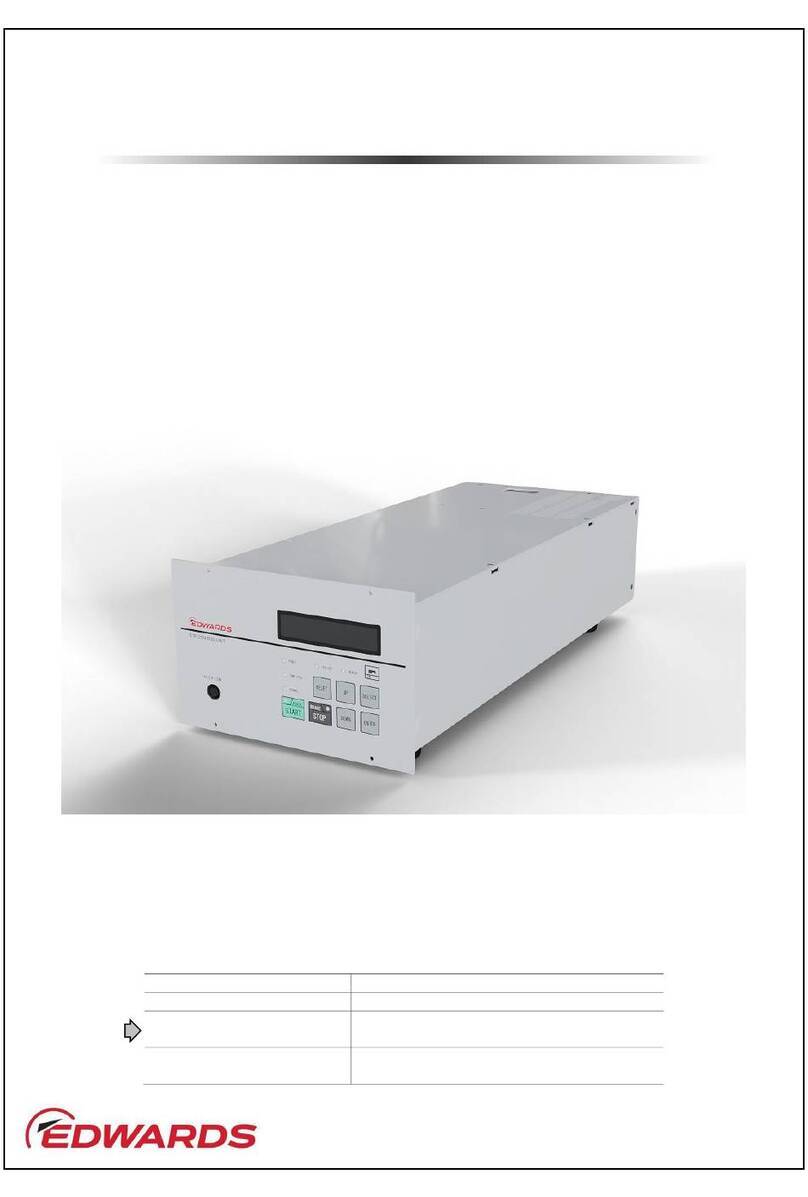
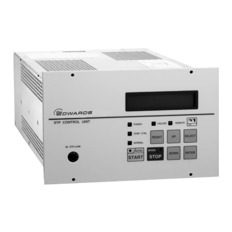
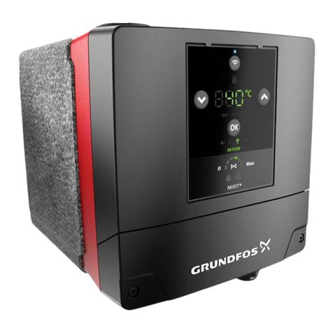
7 SCU-801 control unit 7
8 Configuration of the STP pump with the TMS 8
9 SCU-801 dimensions (mm) 11
10 SCU-801 front panel 13
11 SCU-801 rear panel 16
12 Installing the SCU-801 18
13 Example of securing the SCU-801 19
14 STP pump connection cable 21
15 TMS connection cable (standard) 22
16 TMS connection cable (STP-A1603 series) 22
17 Power cable 23
18 Connecting method of the power cable without plug 24
19 REMOTE X7 connector 26
20 Connector X3A, X3B, X6 (D-sub 9) 26
21 Tuning procedures 28
22 Confirmation mode 31
23 Error Detailed Information 32
24 Parameter setting method 38
25 Parameter setting method (continued) 39
26 Parameter setting method (continued) 40
27 Parameter setting method (continued) 41
28 Parameter setting method (continued) 42
29 Network address setting 43
30 Manual operation method 45
31 Operational procedures 50
32 REMOTE X7 input signal pins 53
33 REMOTE X7 output signal pins 55
34 Serial communication 61
35 Connector X3A/X3B (D-sub 9) 62
36 Connector X6 (D-sub 9) 63
37 RS485 connections 64
38 FAILSAFE bias resistance 65
39 Grounding example (Both ends grounding) 67
40 Grounding example (single point grounding) 68
41 Example of ring ferrite core installation 68
42 Example of cable installation in metallic duct 68
43 Example of differential signal waveform 69
44 PC to SIM communication 70
45 Block diagram of communication process example 81
46 Example of answer resending process 82
47 Example of response when the command is sent continuously 82
48 Example of command sending during answer data reply 82
49 Example of communication cycle process 83
50 Example of command sending process 84
51 Example of answer receiving process 84


