Chemtronics MoniTurb-F User manual

Chemtronic Waltemode GmbH
Sales- & Service Partner for Your MONITEK Products.
40789 Monheim am Rhein , Niederstr. 14
Phone: +49-(0)2173-57007 Fax: +49-(0)2173-56007
E-mail: info@chemtronic-gmbh.de
Internet: www.chemtronic-gmbh.de
Manual
Version 09.03.2015
Universal Transmitter Model
Messenger

Chemtronic Waltemode GmbH, Niederstr. 14, 40789 Monheim am Rhein, Germany / Sales & Service Partner of Galvanic Applied Sciences Inc.
Phone +49-(0)2173-57007 Fax: +49-(0)2173-56007 E-mail: info@chemtronic-gmbh.de Internet: www.chemtronic-gmbh.de Page 2
Transportation Damages!
Please inspect the instrument immediately after receiving for potential
shipping damages.
For any claims to the transportation insurance or warranty repair, it is
absolutely required to notify transportation damages immediately after
receiving the instrument. In case of obvious damages of the outer
packaging, the carrier must give a receipt for this damage to make
demands for the insurance. In case of a delayed announcement the
insurance will not pay for damages and Chemtronic Waltemode GmbH will
not assume liability for these damages.
Manufacturer and owner of all rights model Messenger:
Galvanic Applied Sciences Inc., Lowell MA, USA
Revised manual by Chemtronic Waltemode GmbH

Chemtronic Waltemode GmbH, Niederstr. 14, 40789 Monheim am Rhein, Germany / Sales & Service Partner of Galvanic Applied Sciences Inc.
Phone +49-(0)2173-57007 Fax: +49-(0)2173-56007 E-mail: info@chemtronic-gmbh.de Internet: www.chemtronic-gmbh.de Page 3
Content
TRANSPORTATION DAMAGES! ................................................................................................................................................. 2
COPYRIGHT.................................................................................................................................................................................. 5
WARRANTY CONDITIONS........................................................................................................................................................... 5
Shipment of the instrument......................................................................................................................................................... 5
SAFETY INSTRUCTIONS ............................................................................................................................................................. 6
BEFORE INSTALLATION AND STARTUP .................................................................................................................................. 7
System Inspection ....................................................................................................................................................................... 7
General Installation guidelines ................................................................................................................................................... 7
GENERAL INFORMATION ........................................................................................................................................................... 8
Introduction .................................................................................................................................................................................. 8
SPECIFICATIONS:........................................................................................................................................................................ 9
DIFFERENT VERSIONS: MESSENGER TRANSMITTER ............................................................................................................ 9
DIMENSIONAL DRAWINGS ....................................................................................................................................................... 10
WIRING DIAGRAM (MESSENGER TRANSMITTER) ................................................................................................................. 11
Main Board.................................................................................................................................................................................. 11
Optional Relay Board................................................................................................................................................................. 11
JUMPER POSITIONS MODEL MESSENGER ............................................................................................................................ 12
Jumper Positions (Gain Setting)............................................................................................................................................... 13
SOFTWARE INSTALLATION (MESSENGER GRAPH) ............................................................................................................. 14
RS-232 Interface ......................................................................................................................................................................... 17
RS-485 Pins – at Messenger...................................................................................................................................................... 17
INTERCONNECTIONS TO PC / LAPTOP (RS 232) ................................................................................................................... 18
Turn Messenger and PC / laptop back on................................................................................................................................ 18
Messenger RS232 Wiring Diagram ........................................................................................................................................... 18
INTERCONNECTIONS TO PC / LAPTOP (USB)........................................................................................................................ 19
Using the optional USB to RS485 Interface Converter Model USB Nano.............................................................................. 19
MENU LAYOUT AND OPERATION............................................................................................................................................ 20
MENU LAYOUT AND OPERATION............................................................................................................................................ 20
Messenger Software Navigation Tree (Operator) .................................................................................................................... 20
Messenger Software Navigation Tree (Technician) ................................................................................................................. 21
Messenger Software Navigation Tree (Factory Level) ............................................................................................................ 22
SETUP AND CALIBRATION....................................................................................................................................................... 23
Field Calibration and Curve Fitting........................................................................................................................................... 23
Access Levels and Codes ......................................................................................................................................................... 24
Analog Outputs and Alarms...................................................................................................................................................... 27
Display Units .............................................................................................................................................................................. 28
Data Trending Display and RS-232 Output. ............................................................................................................................. 28
Self-Cleaning Interval................................................................................................................................................................. 29
SYSTEM AND TROUBLESHOOTING ........................................................................................................................................ 30
View Channel Output Display ................................................................................................................................................... 30
Factory Calibration .................................................................................................................................................................... 30
Toggling Between Factory and User Calibration .................................................................................................................... 31
Default parameters:.................................................................................................................................................................... 31
Error and Warning Messages.................................................................................................................................................... 31
SOFTWARE UPGRADING.......................................................................................................................................................... 34
Firmware ..................................................................................................................................................................................... 34
PC Version (Messenger Graph Software) ................................................................................................................................ 34
OPTIONAL LAMP control board ............................................................................................................................................... 36
EXTERNAL LAMP CONTROL CONNECTOR PIN OUT: ........................................................................................................... 36
INTERNATIONALIZATION.......................................................................................................................................................... 38
Select Language......................................................................................................................................................................... 38
ON-LINE HELP MENUS AND RELATED CONTENTS ............................................................................................................... 38
MAIN MENU ................................................................................................................................................................................ 38
SET CALIBRATION MENU ......................................................................................................................................................... 39
Process Calibration.................................................................................................................................................................... 40
Build Calibration ........................................................................................................................................................................ 40

Chemtronic Waltemode GmbH, Niederstr. 14, 40789 Monheim am Rhein, Germany / Sales & Service Partner of Galvanic Applied Sciences Inc.
Phone +49-(0)2173-57007 Fax: +49-(0)2173-56007 E-mail: info@chemtronic-gmbh.de Internet: www.chemtronic-gmbh.de Page 4
View / Edit Calibration................................................................................................................................................................ 41
Fit Data ........................................................................................................................................................................................ 41
Copy Factory Table .................................................................................................................................................................... 42
Build Calibration ........................................................................................................................................................................ 42
View / Edit Calibration................................................................................................................................................................ 42
SETUP RESULTS ....................................................................................................................................................................... 43
Setup Results Nametag (Panel PC version only) .................................................................................................................... 43
Setup Results Equation ............................................................................................................................................................. 44
Setup Sensor Equation.............................................................................................................................................................. 44
Setup Numerical Display (Panel PC version only) .................................................................................................................. 45
Setup Graphical Display (Panel PC version only) ................................................................................................................... 45
Set Results Units (Panel PC version only) ............................................................................................................................... 46
Setup Data Logging ................................................................................................................................................................... 46
Setup Storage Size..................................................................................................................................................................... 46
Bubble Reject Threshold........................................................................................................................................................... 47
Set Results Offsets (manual zero adjust)................................................................................................................................. 47
SETUP INPUTS / OUTPUTS MENU............................................................................................................................................ 48
Set LCD Display (Version with LCD- display only) .................................................................................................................. 48
LCD version, Enter nametag, measurement unit and decimal resolution............................................................................. 48
Set Analog Outputs.................................................................................................................................................................... 49
Assign Digital Inputs.................................................................................................................................................................. 49
Set Alarms................................................................................................................................................................................... 50
Set Messenger Unit ID ............................................................................................................................................................... 51
DIAGNOSTIC MENU ................................................................................................................................................................... 52
File Menu..................................................................................................................................................................................... 52
Save Parameters to File ........................................................................................................................................................ 52
Load Parameters from File ................................................................................................................................................... 52
View Channel Outputs ............................................................................................................................................................... 53
Adjust Hardware Settings.......................................................................................................................................................... 53
Zero Dark Current ...................................................................................................................................................................... 54
Optimize Channel Signal Auto .................................................................................................................................................. 54
Optimize Channel Signal Manual.............................................................................................................................................. 55
Calibrate Analog Outputs .......................................................................................................................................................... 56
ADC-GAIN Manual...................................................................................................................................................................... 56
Hardware Test............................................................................................................................................................................. 57
Test Relays ................................................................................................................................................................................. 58
CLEAR/RESET MENU ................................................................................................................................................................ 59
Clear Process Calibration.......................................................................................................................................................... 59
Clear Factory Calibration........................................................................................................................................................... 59
Reset Alarms .............................................................................................................................................................................. 59
Software Revision ...................................................................................................................................................................... 59
SET CLEANING EVENT.............................................................................................................................................................. 60
SET ACCESS CODE ................................................................................................................................................................... 61
SET ACCESS LEVEL.................................................................................................................................................................. 61
MEASUREMENTS SCREEN (PANEL PC VERSION ONLY!) .................................................................................................... 62
Graph Settings (Panel PC Version only) .................................................................................................................................. 67
SENSOR LIST FOR MODEL MESSENGER ............................................................................................................................... 69
TECHNICAL DATA...................................................................................................................................................................... 70
DECLARATION OF CONFORMITY (CE).................................................................................................................................... 71

Chemtronic Waltemode GmbH, Niederstr. 14, 40789 Monheim am Rhein, Germany / Sales & Service Partner of Galvanic Applied Sciences Inc.
Phone +49-(0)2173-57007 Fax: +49-(0)2173-56007 E-mail: info@chemtronic-gmbh.de Internet: www.chemtronic-gmbh.de Page 5
COPYRIGHT
2015 Chemtronic Waltemode GmbH
This manual including all of its parts are protected by copyright.
Any further use beyond the copyright laws is not allowed without the written approval of Chemtronic Waltemode
GmbH. There are no further reaching warranty claims to take because of the content of existing document.
Manufacturer and owner of all rights model Messenger:
Galvanic Applied Sciences Inc., Lowell MA, USA
Revised manual by Chemtronic Waltemode GmbH
WARRANTY CONDITIONS
The warranty for this product takes place according to the legal provisions. As places of warranty we explicitly
name Galvanic Applied Sciences Inc. (Lowell USA) or Chemtronic Waltemode GmbH, Monheim am Rhein
(Germany). In case of warranty service at the customer site, we will charge additional expenses e.g. travel
expenses, overnight cost, etc. Consumable parts as well as wearing parts e.g. lamps, gaskets, etc. are not covered
by warranty. Improper use, gross negligence, use of the system outside of the technical specifications, missing or
improper maintenance will cause a loss of the warranty claim. Please pay attention to our general terms of contract.
Non-warranty
Chemtronic Waltemode GmbH takes no responsibility or warranty for technical or editorial mistakes or omissions in
this document. The information in Chemtronic Waltemode GmbH reserves all rights to make changes to this
document without announcement. Chemtronic Waltemode GmbH is by no means liable for any consequential
damages or miscellaneous damages, which occur during the use or storage of the system. Some countries do not
allow the limitation of liability, so that this exclusion is possibly not valid for you.
Improper installation / operation of the system
Warranty is void if the system is installed improperly, handled improperly, used outside of the technical
specifications (of the instrument), or damaged by gross negligence.
Storage
Please inspect the instrument immediately after receiving for potential shipping damages.
If the instrument has already been unpacked for inspection or testing, or if the instrument has been removed from
the process and it is not to be installed or reinstalled for more than 1 day, the following procedure should be
observed:
1. If the instrument has been in service, the wetted portion should be thoroughly cleaned than thoroughly dried.
2. In case the original packing material is not available place the instrument in a sealed heavy plastic bag with a
desiccant added to assure clean dry storage.
3. The instrument should then be stored in a protected area until time of installation.
Shipment of the instrument
Please clean the instrument carefully before shipment (e.g. for revision / repair). Please use fixed packaging
material to protect the instrument against any shipping damages.

Chemtronic Waltemode GmbH, Niederstr. 14, 40789 Monheim am Rhein, Germany / Sales & Service Partner of Galvanic Applied Sciences Inc.
Phone +49-(0)2173-57007 Fax: +49-(0)2173-56007 E-mail: info@chemtronic-gmbh.de Internet: www.chemtronic-gmbh.de Page 6
SAFETY INSTRUCTIONS
Pay attention to the following general safety instructions during use and operation of the system.
Ignoring these instructions or special warnings inside of this manual can damage the sensor, cause
inaccurate measurements, and possibly result in unsafe installations. Chemtronic Waltemode GmbH will
not take any responsibility for consequences arising from ignoring the safety instructions and warnings.
For all chemical liquids
The product you measure is may be toxic or otherwise harmful to human health. Observe appropriate
precautions when handling and disposing the liquid. Review the appropriate published material safety
data sheets regarding the safe handling and disposal of all reagents or standards.
Electrical installation
Qualified technical personnel must install the electrical installation of the system. This instrument
requires an input of 90-260VAC at 50-60 Hertz (unless otherwise specified). A 24VDC/AC power supply
is optional.
Hazardous area
DO NOT INSTALL the system in hazardous area without the optional Ex-proof equipment. Operation of
non Ex- proof systems in hazardous area will cause a high risk.
Using the system in hazardous areas (Ex Zone I / Ex Zone II) will
only be safe with the installation of the optional special Ex-proof
designs including all required certifications
Maintenance
Always disconnect the instrument from power during maintenance, replacement of components,
installation of additional components or any other operations at the open instrument. Only qualified
technical personnel must perform this work.
Operating the instrument with open enclosure
Only qualified technical personnel should operate the instrument when the enclosure is open. Take care
that no moisture enters the enclosure.
Some components inside the instrument are energized with
voltages, which can cause lethal shocks in case of contact. Be
careful during installation, handling and operation of the
instrument.
Improper installation / operation of the system
Warranty is void if the system is installed improperly, handled improperly, used outside of the
technical specifications (of the instrument), or damaged by gross negligence.

Chemtronic Waltemode GmbH, Niederstr. 14, 40789 Monheim am Rhein, Germany / Sales & Service Partner of Galvanic Applied Sciences Inc.
Phone +49-(0)2173-57007 Fax: +49-(0)2173-56007 E-mail: info@chemtronic-gmbh.de Internet: www.chemtronic-gmbh.de Page 7
BEFORE INSTALLATION AND STARTUP
System Inspection
Check to ensure that all components of the instrument have arrived safely. Included should be: the Messenger Transmitter, the
Sensors and the cable sets and Manual.
The Messenger versions without display and with LCD include typically additional a Cd- Rom with Messenger Graph
Software and an Interface adapter Model USB-Nano.
If there is any damage to the equipment or if anything is missing please contact us immediately. Save the packing
material for future system storage or shippingI
Please read the additional safety instructions before installation and start-up!
General Installation guidelines
1. Transmitter and Sensors are sensitive components, do not drop and handle with care.
2. Follow the wiring diagram (pay attention to sensors manual) during installation of the system.
3. The process temperature and pressure cannot exceed the specification of the delivered Sensor.
4. Avoid air and gas bubbles inside the sensor, they cause disturbances. Nois
e and drift of the measurement would be the result (th
bubbles are not expected at a pressure upwards of 2 bar in aqueous solutions).
5. Please do not use the system in case of any visible mechanical damages!
6. The Messenger enclosure fits IP65 / Nema 4x protection class we recommend a dry / dust free area.
7. The ambient temperature for the transmitter must be in a range of -10°C to 50°C (use dry purge air above 40°C)
8. AC power consumption of the Messenger Transmitter is less than 50 Watts
9. Transmitter relay ratings for alarms and external devices are 2 A at 250V~ maximum
10. Do not operate with open enclosure. Exposed electronics will promote the risk of electrical shock and might cause damage to t
he
11. Do not alter cable length. The instrument was calibrated
with a specified cable length. Altering cable length can cause unstable s
and void instrument calibration.
12. Ship the instrument in the original packing material to avoid damage to the sensor or transmitter.
13. Mishandling of the system is not covered under warranty. Do not disconnect the interior wiring of the sensor.
14. Proper instrument grounding: The instrument must be grounded to avoid electrical shock hazards to person
nel, damage to the un
erroneous operation.
WARNING: MAKE SURE THE AC POWER MAINS ARE SWITCHED OFF OR OTHERWISE
DISCONNECTED BEFORE YOU BEGIN WIRING THE SYSTEM TO AVOID THE POSSIBILITY OF ELECTRICAL
SHOCK. IT IS A GOOD PRACTICE TO INSTALL A MAIN POWER CUTOFF SWITCH NEAR THE SYSTEM WITH
EXTERNAL MAIN FUSES.
THE SYSTEM REQUIRES AN AC-GROUND (EARTH GROUND) AND ALL SENSORS CONNECTED TO
THE TRANSMITTER MUST BE GROUNDED
Please note. The following points are important to avoid damages of the Sensors at
high temperature applications:
•Please connect purge air (cooling) before process insertion (dry, oil- & dust free instrument air )
•Leave air output open
•Do not interrupt the air cooling
•
Remove the Sensor immediately from the process in case air purge is not guarantied!

Chemtronic Waltemode GmbH, Niederstr. 14, 40789 Monheim am Rhein, Germany / Sales & Service Partner of Galvanic Applied Sciences Inc.
Phone +49-(0)2173-57007 Fax: +49-(0)2173-56007 E-mail: info@chemtronic-gmbh.de Internet: www.chemtronic-gmbh.de Page 8
General Information
Introduction
Monitek Messenger is a compact, highly efficient, and expandable system that is designed to interface
to a broad range of Monitek / Galvanic / Chemtronic sensors. It also has the capability to interface with
multiple and different sensors at the same time. It’s modular design approach enables several
applications to be customized for a variety of measurements, such as Turbidity, Suspended solids,
Color and % Concentration using optical in-line Sensors. The Messenger may be linked with Personal
Computer, Laptop or Netbook operating Windows XP / Vista / 7 or a Panel PC (also called a TPC), the
GUI (Graphical User Interface) offers completely menu-driven screens that are easy to understand and
also has online help. The GUI interface is designed to allow three access levels (Operator, Technician
and Factory) to prevent an unskilled operator from changing any critical parameter in the setup of the
transmitter. The interface is intuitive with no need for programming codes or program numbers. The
system also includes some self-check operations as well as the ability to access the basic
measurement values without the use of a multi-meter or even physically accessing the electronics. The
system includes the ability to perform field calibrations while the instrument is installed in the process
and is operating. It comes factory pre-configured to your application. For most accurate setup we
recommend that the user calibrate on his process sample condition. Please refer to Process calibration
Icons used in this User’s Manual
Important notice!
Cautions indicate situations that could damage the Monitek Messenger or
sensor. Cautions are printed in mixed case characters in boldface font

Chemtronic Waltemode GmbH, Niederstr. 14, 40789 Monheim am Rhein, Germany / Sales & Service Partner of Galvanic Applied Sciences Inc.
Phone +49-(0)2173-57007 Fax: +49-(0)2173-56007 E-mail: info@chemtronic-gmbh.de Internet: www.chemtronic-gmbh.de Page 9
Specifications:
Sensors: MoniTurb-F, MoniTurb-FS, MoniSpec-AD, AP2, LAS, MoniSpec A, MoniTurb-S, TS2,
Model 22, Model 25 Probes (includes CSK, CSH, CSS), Model 450, 210 with external
power supply, more …..
Number of Sensors: 1 to 4 sensors. Each sensor may be linked to a separate 8 points Calibration table with 1st
order or Curve fit linearization technique.
Area Classification: General Purpose (optional Hazardous area Zone 1 & 2)
Environmental:
Operating Temp:
-14 °F to 122 °F (-10 °C to 50 °C), air purge required for cooling above temperatures of 104°F (40°C)
Humidity: 0 to 95% RH, non condensing
User Interface:
Alarms: Low High Alarms and General Fault Alarm are user programmable, latching or non-
latching, energized or de-energized with alarm delay and hysteresis.
Display: Optional, 4 lines by 20 Characters backlight LCD.
Programming: Using PC, Laptop, Netbook or touch screen Panel PC.
Analog Outputs: 2x 0/4-20mA Isolated. Optional 2additional outputs 0 to 1000 Ohm
Internal Relays: Optional, 4 relays fully programmable rated 2A/250VAC
Digital Inputs: Four Digital Inputs, fully programmable with activate levels of 5 to 24 VDC
Digital Output: RS-232 or RS-485 using Modbus RTU protocol.
Input Power: 90 to 260 VAC 50/60 Hz optional 24V
Power consumption: less than 50 watts
Case Material: 304 Stainless Steel
Approvals CE / CSA
Different versions: Messenger Transmitter
Version without display Version with alpha
numeric LCD Version with Panel PC
(TPC)
A PC / Laptop or Netbook is required for configuration / calibration of the
versions without display and with LCD- display.
The Panel PC (TPC) version allows configuration and calibration without
external equipment. The operation is will be done via touch screen of the
Panel PC.

Chemtronic Waltemode GmbH, Niederstr. 14, 40789 Monheim am Rhein, Germany / Sales & Service Partner of Galvanic Applied Sciences Inc.
Phone +49-(0)2173-57007 Fax: +49-(0)2173-56007 E-mail: info@chemtronic-gmbh.de Internet: www.chemtronic-gmbh.de Page 10
Dimensional Drawings
Messenger (without display)
Messenger (with numeric LCD)
Messenger (with Panel- PC / TPC)

Chemtronic Waltemode GmbH, Niederstr. 14, 40789 Monheim am Rhein, Germany / Sales & Service Partner of Galvanic Applied Sciences Inc.
Phone +49-(0)2173-57007 Fax: +49-(0)2173-56007 E-mail: info@chemtronic-gmbh.de Internet: www.chemtronic-gmbh.de Page 11
Wiring Diagram (Messenger Transmitter)
Main Board
Optional Relay Board
See additional wiring instructions in your sensors manual!

Chemtronic Waltemode GmbH, Niederstr. 14, 40789 Monheim am Rhein, Germany / Sales & Service Partner of Galvanic Applied Sciences Inc.
Phone +49-(0)2173-57007 Fax: +49-(0)2173-56007 E-mail: info@chemtronic-gmbh.de Internet: www.chemtronic-gmbh.de Page 12
Jumper Positions Model Messenger
All jumpers are typically factory configured according to sensor and application.
Please contact our service before you change any jumper position!
Some components inside the instrument are energized with voltages, which can
cause lethal shocks in case of contact. Be careful during installation, handling
and operation of the instrument. Disconnect from supply power.
Firmware
(JP10)
Figure 128
This jumper (JP10) is used to unlock the hardware for a firmware update.
Firmware updates should be done by Service personal only!
•Standard jumper position (JP10) = not jumpered (open)
Signal Gain (JP1 to JP8)
•Jumper positions (JP1 to JP8) = depending on application, see next page for details.
Lamp current (JP11 & JP12)
Position for lamp
current 1A
Position for lamp
current 350mA & less
Read chapter „
Sensor List for Model Messenger” before changing JP11, JP12
jumper position!
Only qualified technical personnel must perform this work.
•Jumper positions (JP11 & JP12) = depending by Sensor
System Reset (JP9)
Only qualified technical personnel must perform this work. This Jumper allows a complete
system reset by hardware, take notice al user programmed settings will be lost!
•Standard jumper position (JP9) = not jumpered (open)

Chemtronic Waltemode GmbH, Niederstr. 14, 40789 Monheim am Rhein, Germany / Sales & Service Partner of Galvanic Applied Sciences Inc.
Phone +49-(0)2173-57007 Fax: +49-(0)2173-56007 E-mail: info@chemtronic-gmbh.de Internet: www.chemtronic-gmbh.de Page 13
Jumper Positions (Gain Setting)
Only qualified technical personnel must perform this work.
Please contact our service before you change any jumper position!
Some components inside the instrument are energized with voltages, which
can cause lethal shocks in case of contact. Be careful during installation,
handling and operation of the instrument. Disconnect from supply power.
You can change the hardware gain of the Messenger transmitter in case the “optimize signal”
values are to high or to low. See chapter “Optimize Signal”.
Jumper Positions „low gain“
Jumper Positions „high gain“
Jumpers are located directly behind the connectors for the signal inputs.
See wiring diagram at Page 13
Each signal input can be configured individually:
JP1 and JP5 = 1. Signal Input
JP2 and JP6 = 2. Signal Input
JP3 and JP7 = 3. Signal Input
JP4 and JP8 = 4. Signal Input
Chemtronic Waltemode GmbH, Niederstr. 14, 40789 Monheim am Rhein, Germany / Sales & Service Partner of Galvanic Applied Sciences Inc.
Phone +49-(0)2173-57007 Fax: +49-(0)2173-56007 E-mail: info@chemtronic-gmbh.de Internet: www.chemtronic-gmbh.de Page 14
Software Installation (Messenger Graph)
The Software Installation is not required at Panel PC (TPC) version of the
Transmitter. Panel PC version arrives with installed Software!
System Requirements
Supported Operating Systems Windows XP, Vista, 7
RAM 32MB
Hard Disk Space 5MB
.
Installation procedure Messenger Graph Software
I. Close any open programs that are running on your computer before starting the installation.
II. Double click on setup.exe.
III. As the installation progresses, follow the instructions on the screen. Some Windows system files
will be updated to newer versions during installation of Messenger software. If these updates are
done, you will be required to reboot your PC. If so, repeat steps 1 through 2 of the installation
procedure to continue with the installation. Once the installation of Messenger software is
complete, you will be required to restart your computer once again for proper functioning of the
software.
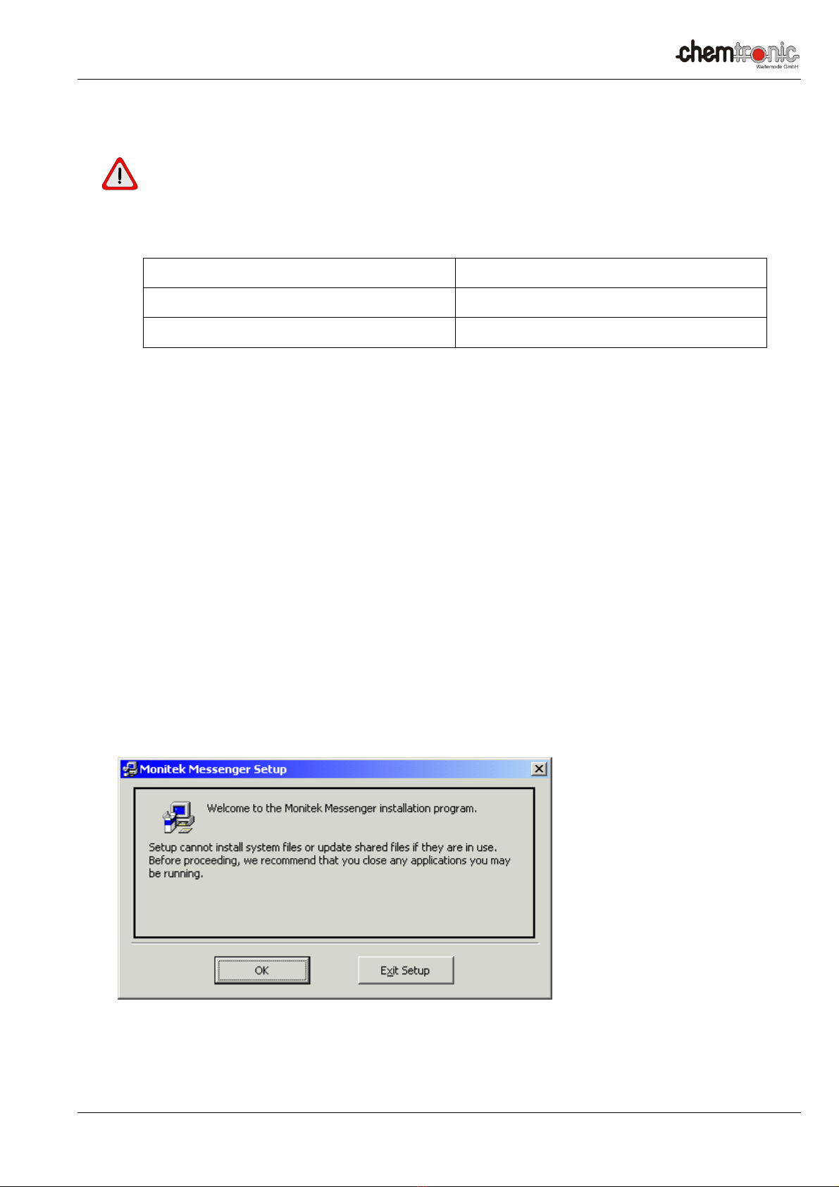
IV. Welcome screen shown below will appear, Click OK to continue the installation process. To abort
the installation process click Exit Setup.

Chemtronic Waltemode GmbH, Niederstr. 14, 40789 Monheim am Rhein, Germany / Sales & Service Partner of Galvanic Applied Sciences Inc.
Phone +49-(0)2173-57007 Fax: +49-(0)2173-56007 E-mail: info@chemtronic-gmbh.de Internet: www.chemtronic-gmbh.de Page 15
V. Choose the Destination location.
VI. To change the default destination location click on Change Directory. Choose new
destination location using the following screen.

Chemtronic Waltemode GmbH, Niederstr. 14, 40789 Monheim am Rhein, Germany / Sales & Service Partner of Galvanic Applied Sciences Inc.
Phone +49-(0)2173-57007 Fax: +49-(0)2173-56007 E-mail: info@chemtronic-gmbh.de Internet: www.chemtronic-gmbh.de Page 16
VII. Choose the program group under which the application has to appear.
VIII. Click Continue.
IX. Dialog showing the status of the files being copied will be displayed.
X. On Completion of Installation Process Message “Installation process complete” will appear.
XI. Click on OK to finish the installation process.

Chemtronic Waltemode GmbH, Niederstr. 14, 40789 Monheim am Rhein, Germany / Sales & Service Partner of Galvanic Applied Sciences Inc.
Phone +49-(0)2173-57007 Fax: +49-(0)2173-56007 E-mail: info@chemtronic-gmbh.de Internet: www.chemtronic-gmbh.de Page 17
RS-232 Interface
RS-232 Pins - at Messenger
Messenger Pins PC / Laptop
16 DSR (-) 4 DTR
17 TX (Out) 2 RX (In)
18 RX (In) 3 TX (Out)
19 GND 5 GND
Reference Pins RS232 - at PC / Laptop / Netbook (9 Pin Sub-D)
Pin Signal Dir Funktion
1 DCD/RLS
D IN Carrier Detect
2 RXD IN Receive Data
3 TXD OUT Transmit Data
4 DTR OUT Data Term
Ready
5 GND Ground
6 DSR IN Data Set
Ready
7 RTS OUT Request to
Send
8 CTS IN Clear to Send
9 RI IN Ring Indicator
RS-485 Pins – at Messenger
Messenger Pin PC / Laptop
13 (-) -- --
14 (+) -- --
15 GND -- --

Chemtronic Waltemode GmbH, Niederstr. 14, 40789 Monheim am Rhein, Germany / Sales & Service Partner of Galvanic Applied Sciences Inc.
Phone +49-(0)2173-57007 Fax: +49-(0)2173-56007 E-mail: info@chemtronic-gmbh.de Internet: www.chemtronic-gmbh.de Page 18
Interconnections to PC / Laptop (RS 232)
Install the software “Messenger Graph” to your computer
Turn Messenger and PC / Laptop off.
Connect the RS232 cable according to wiring diagram.
Connect your PC / Laptop via the RS232 jack to Messenger the transmitter.
Turn Messenger and PC / laptop back on.
Messenger RS232 Wiring Diagram

Chemtronic Waltemode GmbH, Niederstr. 14, 40789 Monheim am Rhein, Germany / Sales & Service Partner of Galvanic Applied Sciences Inc.
Phone +49-(0)2173-57007 Fax: +49-(0)2173-56007 E-mail: info@chemtronic-gmbh.de Internet: www.chemtronic-gmbh.de Page 19
Interconnections to PC / Laptop (USB)
Using the optional USB to RS485 Interface Converter Model USB Nano
An interface converter USB to RS232 can not be used to configure or calibrate
the transmitter model Messenger! Using this type of converter will cause a
crash of the Messenger Graph Software!
The interface converter USB- Nano is used to configure / calibrate the Transmitter via USB-
interface. Please do not access the menu “Measurements Screen” if you use this converter this
may crash of the Messenger Graph software!
1. Install the software “Messenger Graph” to your computer.
2. Connect the RS485-converter to the USB- interface of your computer.
3. Install the driver software of the RS485- converter model USB- Nano.
Take notice:
Restart your computer before you proceed with item 3 otherwise you may get problems with
configuration.
4. Start the Windows Control Panel and select System, Hardware, Device Manager, COM and LPT.
5. Assign a COM port, COM1, COM2, COM3 or COM4 to your interface converter (we recommend COM1).
6. Close Device Manager and Control Panel.
7. Connect transmitter mod. Messenger to Interface converter model USB- Nano.
USB- Nano connector A: to terminal 13 model Messenger
USB- Nano connector B: to terminal 14 model Messenger
USB- Nano Shield: to terminal 15 model Messenger
8. Start the software „Messenger Graph“.
9. Call up the “Main Menu” and select the sub- menu
Inputs/Outputs – Set COM Port. Please proceed directly with step 10 in case your COM port is assigned to
COM1.
10. Enter the in item 4 selected Port (COM-COM4) and enter:
Baud 57600, Modbus- Normal. Please proceed directly with step 10 in case your COM port is assigned to
COM1.
11. Return to the START/EXIT-Menu and select „GO ONLINE”.
Background of button „GO ONLINE” and the dot in the upper right corner, change to green color.
Some Windows Installations may come up with the message:
„Invalid procedure call or argument“.
Confirm the Message with the OK button.
Take notice, the dot in the upper right corner has to stay green.

Chemtronic Waltemode GmbH, Niederstr. 14, 40789 Monheim am Rhein, Germany / Sales & Service Partner of Galvanic Applied Sciences Inc.
Phone +49-(0)2173-57007 Fax: +49-(0)2173-56007 E-mail: info@chemtronic-gmbh.de Internet: www.chemtronic-gmbh.de Page 20
Menu layout and Operation
Messenger Software Navigation Tree (Operator)
Start/Exit Menu
Setup Inputs/
Outputs
Measurement
Screen
Previous
Data
Set Access
Level
Set Cleaning
Event
Select Messenger
Main Menu
Select Language
Graph
Settings
Copy Data
Diagnostic
Menu
Online
Data
Copy Image
Save As Bmp
Set Alarms
Soft are Revision
Clear/Reset Menu
Functions
Reset Alarms
This manual suits for next models
5
Table of contents


