Rev. 0-201 PRO-series Model C3 Conductivity Transmitter
5
CONDENSED OPERATING INSTRUCTIONS
This manual contains details for all operating aspects of the instrument. The following condensed in-
structions are provided to assist you in getting the instrument started up and operating as quickly as
possible. These condensed instructions only pertain to basic conductivity measurement opera-
tion. To measure resistivity or TDS, or to use specific features of the instrument, refer to the appropriate
sections in this manual for instructions.
A. CONNECTING SENSOR/CONFIGURING TEMPERATURE ELEMENT TYPE
1. After properly mounting the transmitter (PART TWO, Section 2), connect the GLI enhanced
performance contacting conductivity sensor, matching wire colors to terminals as indicated:
Sensor Wire Colors Connect To TB2
Red Terminal 1
No connection (unused) Terminal 2
Inner and Outer Shield Wires Terminal 3
White Terminal 4
Blue Terminal 5
No connection (unused) Terminal 6
Black Terminal 7
2. The transmitter is supplied factory-set for automatic temperature compensation using the Pt
1000 ohm temperature element built into GLI enhanced performance contacting conductivity
sensors. For fixed MANUAL temperature compensation, you must change the temperature ele-
ment type (see PART THREE, Section 3.2, subheading “Select TEMP ELEMENT Type”).
B. CONNECTING DC POWER
Refer to PART TWO, Section 3.2, 3.3, 3.4 or 3.5 to connect DC power to the transmitter.
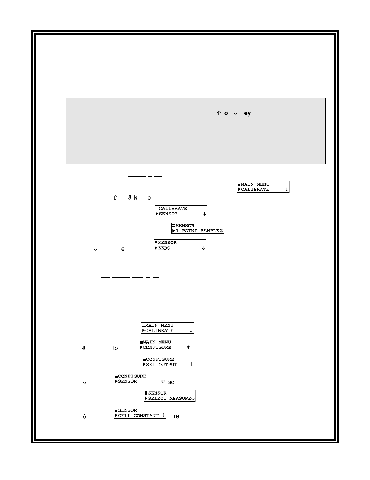
C. CALIBRATING THE TRANSMITTER
The transmitter must be calibrated so that measured values will correspond to actual process values.
It can be traditionally “wet”calibrated. However, since measured conductivity is greatly affected by
small changes in temperature, GLI strongly recommends using its DRY-CAL method for highest
measuring accuracy of conductivity and temperature. Besides, DRY-CAL is actually a normal part of
configuring the sensor characteristics during initial startup, and DRY-CAL eliminates the need for
conductivity reference solutions. This method also automatically sets the transmitter measuring
range to match the inherent range of the sensor’s cell constant. For more details about the benefits
of DRY-CAL, refer to the “Calibration Tip!”in PART THREE, Section 4.1.
NOTE: DRY-CAL eliminates the need for periodic re-calibration! The only requirement, depending on
the application, may be to periodically clean the sensor. Only when the sensor is replaced is
it necessary to perform a new DRY-CAL calibration.
Calibration Tip! Each contacting conductivity sensor has a unique zero point and offset. Conse-
quently, when calibrating a sensor for the first time, always zero it according to step 1. Zeroing
provides the best possible measuring accuracy.
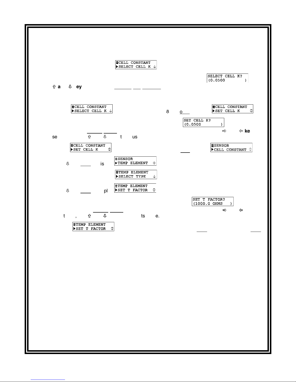
DRY-CAL calibration, routinely attained while configuring the transmitter for sensor characteristics,
requires entry of the sensor’s GLI-certified “CELL K”value and temperature “T FACTOR”which are
unique to each sensor.
(continued on next page)