Cherry Aerospace G83 User manual

1224 East Warner Ave,
Santa Ana, Ca 92705
Tel: 1-714-545-5511
Fax: 1-714-850-6093
www.cherryaerospace.com
THIS TOOL IS OBSOLETE; SEE G83A FOR
REPLACEMENT G83
Lockbolt Power Tool
5130-01-435-3507
1
THE G83 TOOL
THIS TOOL IS OBSOLETE; SEE G83A FOR REPLACEMENT
TABLE OF CONTENTS
Description ................................................................................................................................................................................1
Specifications for G83 ..............................................................................................................................................................1
Safety Warnings .......................................................................................................................................................................2
How to Use the G83 .................................................................................................................................................................3
Maintenance and Repair ..........................................................................................................................................................3
Fill and Bleed Instructions ........................................................................................................................................................4
Trouble Shooting ......................................................................................................................................................................4
Overhaul ....................................................................................................................................................................................5
Air Valve ......................................................................................................................................................................5
Head Sub-Assembly ...................................................................................................................................................5
Handle Sub-Assembly ................................................................................................................................................6
G83 Pulling Heads ............................................................................................................................................................. 6 & 7
Cross Section Drawing of G83 .................................................................................................................................................8
Parts List for G83 Riveter .........................................................................................................................................................9
Exploded View of G83.............................................................................................................................................................10
Declaration of Conformity ........................................................................................................................................Back Cover
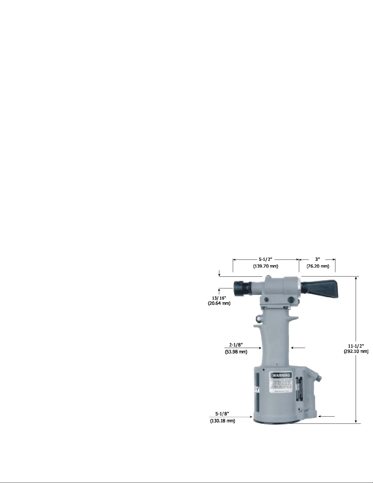
DESCRIPTION
The Cherry G83 pneumatic-hydraulic lockbolt installation tool is a heavy duty production tool designed for high speed, reliable
installation of the most popular sizes of aircraft lockbolts.
This extremely powerful tool has been designed with many
ergonomic features: light weight (4.95 pounds) (2.25 kg.), less
recoil, low noise, and a comfortable fit in the operator’s hand. It can
be operated in any position with one hand.
By bending the rubber pin deflector (63) sideways, 1-1/2" additional
clearance can be obtained.
This tool can also be used to install blind bolts and blind rivets. See
the section on “Pulling Heads” for correct pulling head part number.
SPECIFICATIONS FOR G83
Cherry Aerospace’ (CHERRY) policy is one of continuous
development. Specifications shown in this document may be subject
to change which may be introduced after publication. For the latest
information always consult CHERRY.
AIR PRESSURE 90 to 110 PSI (6.2 to 7.6 bar) .
STROKE 7/16 inch (11.1 mm)
PULLING FORCE 3,750 lbs. (16.7 kN) @ 90 PSI (6.2 bar),
800 lbs. (3.56 kN) on return stroke
CYCLE TIME Approximately one second
WEIGHT 4.95 lbs. (2.25 kg)
NOISE LEVEL 78.4 dB (A)
VIBRATION less than 2.5 m/s2
AIR CONSUMPTION 0.16 SCF/cycle (4.53 L/cycle)

2
SAFETY WARNINGS
Operating this tool with a damaged or missing stem deflector, or using the deflector as a handle, may
result in severe personal injury. The pin deflector should be rotated until the aperture is facing away from
the operator and other persons working in the vicinity.
Approved eye protection should be worn when operating, repairing, or overhauling this tool.
Do not use beyond the design intent.
Do not use substitute components for repair.
Any modification to the tool, pulling heads, accessories or any component supplied by CHERRY®, or their
representatives, shall be the customer’s entire responsibility. CHERRY® will be pleased to advise on any
proposed modification.
The tool must be maintained in a safe working condition at all times and examined at regular intervals for
damage.
Before disassembling the tool for repair, refer to the Maintenance and Repair instructions. All repairs shall
be undertaken only by personnel trained in CHERRY® installation tools. Contact CHERRY® with your
training requirement.
Always disconnect the air line from the tool inlet before attempting to service, adjust, fit or remove any
accessory.
Do not operate the tool when it is directed at any person.
Ensure that the vent holes do not become blocked or covered and that air line hoses are always in good
condition.
Excessive contact with the hydraulic oil should be avoided to minimize the possibility of rashes. Care
should be taken to wash thoroughly.
Operating air pressure should not exceed 110 psi (7.6 bar).
Do not operate the tool without pulling head correctly and securely attached.
Do not operate the tool unless the handle base (66) is fully secured by retaining ring (67) and the base
cover (68) is held in place by retaining ring (69).
All retaining rings, screwed end caps, air fittings, trigger valves and pulling heads should be attached
securely and examined at the end of each working shift.
Do not pull rivet in the air.
The precautions to be used when using this tool must be explained by the customer to all operators. Any
question regarding the correct operation of the tool and operator safety should be directed to CHERRY®.
Do not pound on the rear of the tool head to force rivets into holes as this will damage the tool.
Do not depress the trigger while disconnecting the air bleeder and replacing the cap screw when bleeding
the tool.

3
HOW TO USE THE G83
LOCKBOLTS
After selecting the proper pulling head and attaching it securely to the G83, connect the air line to the tool. Place the lockbolt pin into the workpiece
and place the collar over the pintail. It may be necessary to hold the lockbolt in the application to prevent it from backing out when placing the pulling
head over the serrations.
If you are using a non-self-releasing pulling head, make certain the collar is placed on the lockbolt pintail before placing the pulling head on the pin-
tail. Once the pintail is inserted into the pulling head the jaws will grip the pintail and prevent it from moving out of the front of the pulling head.
If there is sheet gap or a gap between the head of the lockbolt and the workpiece, it may require multiple stroking of the tool for complete installa-
tion. The pintail will eject through the rear of the tool when using H513 Series straight pulling heads. The pintail will eject through the rear of the H563
offset pulling head.
If the tool does not kick off the swaged collar, shims should be added behind the collet of the pulling head. See pulling head installation instructions.
BLIND BOLTS AND RIVETS
Insert the blind bolt or blind rivet stem into the proper pulling head until the head of the rivet is in contact with the pulling head nosepiece. This will
ensure full engagement between the jaws and the rivet stem and will prevent slippage.
Once the rivet stem is inserted in the pulling head, the rivet must be installed. The “stem stop” in the pulling head (H701 B-456) will prevent the man-
drel from moving back out the front of the head.
Insert the rivet into the application and pull the trigger to activate the tool. Upon the release of the trigger, the stem will eject to the rear of the tool
(when using the H701 B-456 straight pulling head). When using the H781-456 offset pulling head, the stem will eject through the offset pulling head
to the rear. When using the H753A-456 right angle pulling head, the stem will eject out the front.
MAINTENANCE AND REPAIR
The G83 has been manufactured to give maximum service with minimum care. In order that this may be accomplished, the following recommen-
dations should be followed:
1.The hydraulic system should be full of oil and free from air at all times.
2. Keep excessive moisture and dirt out of air supply to prevent wear of air valve, air cylinder and air piston.
3.Tool should be routinely inspected for oil leaks. Oil leaking around screws (49) indicates that a screw is loose or a Stat-O-Seal (50)
needs replacing. Oil leaking around the small by-pass hole near the base of the handle grip (1) would indicate worn or damaged O-
rings (19).
Use automatic transmission fluid Type “A” (no substitutes). Cherry® Aerospace recommends using, Dexron® III ATF.
DEXRON III OIL SAFETY DATA
FIRST AID
Skin: Wash thoroughly with soap and water as soon as possible. Casual contact requires no immediate attention.
If irritation develops, consult a physician.
Ingestion: Seek medical attention immediately. DO NOT INDUCE VOMITING.
Eyes: Flush with copious amounts of water. If irritation develops, consult a physician.
Inhalation: No significant adverse health effect are expected to occur on short term exposure. Remove from contaminated area.
Apply artificial respiration if needed. If unconscious, consult physician.
FIRE
Suitable extinguishing media: CO2, dry powder, foam or water fog. DO NOT use water jets.
ENVIRONMENT
Waste Disposal: In accordance with local, state and federal regulations.
Spillage: Prevent entry into drains, sewers and water courses. Soak up with diatomaceous earth or other inert material. Store in
appropriate container for disposal.
HANDLING
Eye protection required. Protective gloves recommended. Chemically resistant boots and apron recommended. Use in well ventilated area.
COMBUSTIBILITY
Slightly combustible when heated above flash point. Will release flammable vapor which can burn in open or be explosive in
confined spaces if exposed to source of ignition.
STORAGE
Avoid storage near open flame or other sources of ignition.
PROPERTIES
Specific gravity 0.863
Weight per gallon 7.18 lbs.
Open flash point >200°C (392°F)
4
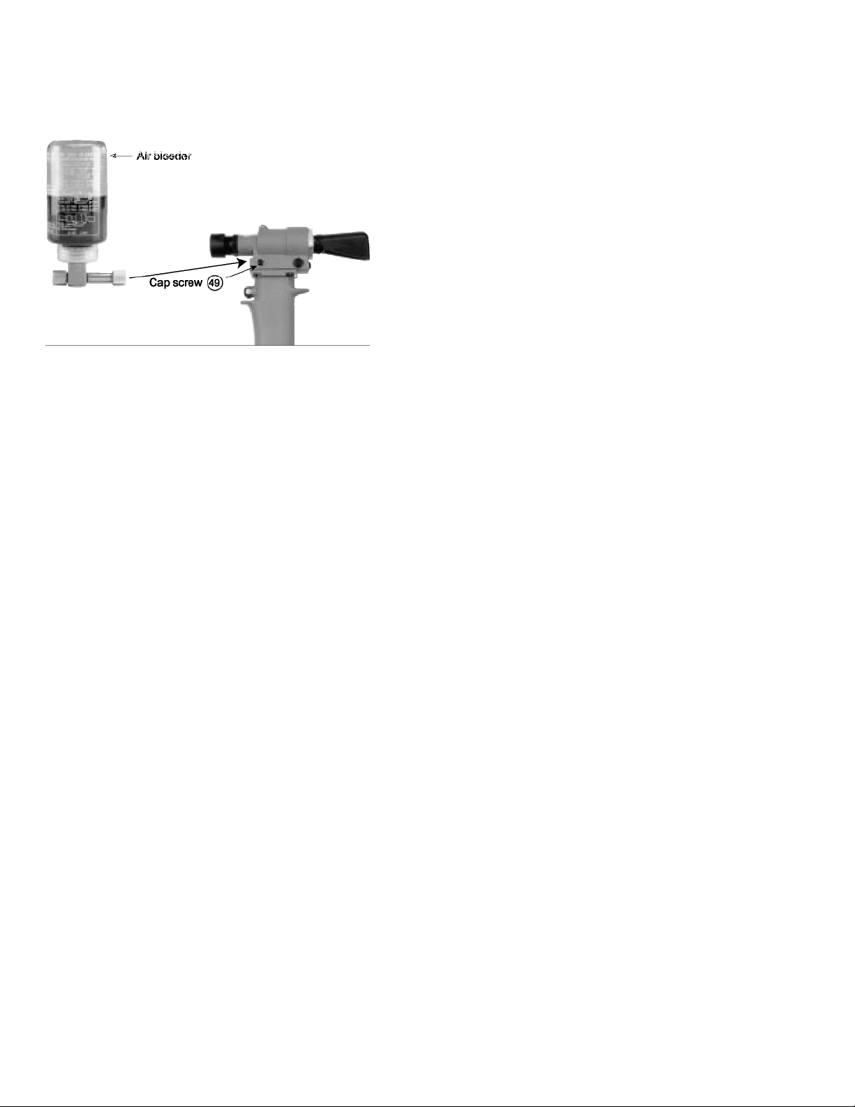
FILL AND BLEED INSTRUCTIONS (see Parts List)
To replace a small amount of oil in the tool, remove cap screw (49) from side of head cylinder (51), attach the Cherry® air
bleeder (700A77), connect the tool to the air line and cycle several times. This will ensure the removal of any air from the
hydraulic system and its replacement with fluid. Should it become necessary to completely refill the tool (such as would be
required after the tool has been dismantled and reassembled), take the following steps:
1. Stand tool upright and connect to air line. Hold trigger down
and when air piston (31) bottoms, disconnect tool from air
line.
2. Head piston (54) should move to the rear position during
Step 1. If it does not, push the piston back manually.
3. Remove the screw (49) and the Stat-O-Seal (50) from the
side of the head cylinder (51). Connect the pressure oil can
filled with automatic transmission fluid Type “A”. See chart.
4. Remove the screw (49) and the Stat-O-Seal (50) from the
rear of the head cylinder (51). Force the fluid into the tool
until it flows out the rear hole. Position the tool in such a way
that the rear hole is the high point. Keep pumping the oil until
all air bubbles are out. Place the screw (49) with the Stat-O-
Seal (50) into the rear hole and tighten.
5. Remove the screw (49) and the Stat-O-Seal (50) from the top of the head cylinder (51). Force the fluid into the tool until it
flows out from the top hole. Position the tool in such a way that the top hole is the highest point. Keep pumping oil until
all the air bubbles are out.
6. Disconnect the pressure oil can from the side hole of the head cylinder (51). Replace screw (49) and Stat-O-Seal (50)
and tighten.
NOTE: For the purpose of bleeding, it is not necessary to remove the pressure relief valve (74) from the head. Do not
remove any of the hex socket set screws from the head or the handle.
7. Holding a cloth over the tool head, attach tool to air line. Excess oil and air will be discharged into cloth. Place the screw
(49) with the Stat-O-Seal (50) into the top hole and tighten.
TROUBLESHOOTING
1. Check the airline for correct pressure at the tool. It must be
90 to 110 PSI (6,2 to 7,6 bar).
2. Check the tool for lack of oil (see Fill and Bleed
Instructions).
3. Check for oil leakage:
Oil leaking around the cap screw (49) in the head
indicates that the screw is loose or the Stat-O-Seal (50)
needs replacing, side, top and rear.
If oil should leak through the by-pass hole at the base of
the handle (1) the O-rings (19) are worn or damaged.
Oil leaking from the front of the head (51) indicates that
O-rings (52) are worn or damaged.
4. Check for excessive air leakage from the air valve:
If spring (4) is broken or dislodged, air will bleed
directly through the bottom of the air valve and the head
piston retreats to its full stroke without returning. See air
valve instructions on Page 5.
If O-ring (9) on plug (10) is worn or damaged, replace.
If O-rings (2) on valve spool (6) are worn or damaged,
replace.
5. Check movement of the head piston (54). If it does not
move freely or is slow in operation:
O-rings (52), (56), (57), and (59) may be damaged and
require replacement.
Piston (54) may be mechanically locked due to damaged
parts.
If O-Ring (17) on power piston (15) is worn or damaged,
replace.
Muffler (11) or air filter (7) inside valve spool (6) may
be plugged with dirt. Clean them thoroughly with normal
solvent and back-blow with compressed air.
Hole in metering screw (8) in valve spool (6) may be
blocked or damaged. Hole diameter should be 0.028"
(0,711 mm). Clear and size or replace valve spool (6).
6. Stem sticks in the pulling head:
Pulling head components need maintenance.
Disassemble the pulling head, clean and replace worn
parts. Reassemble following pulling head instructions.
Spent rivet stems are wedged side by side in the pulling
head from failure to eject stem from tool prior to inserting
next fastener. Disassemble the pulling head, remove
stems and reassemble following pulling head instructions.
5
OVERHAUL (see Parts List)
The disassembly and re-assembly procedures can
be accomplished by following the instructions and
drawings on pages 8 and 10. Use extreme care
during disassembly and reassembly not to
mar, nick or burr any smooth surface that
comes in contact with O-rings. Before installing
O-rings, be sure to apply an O-ring lubricant such
as Lubriplate® 630A, or equivalent.
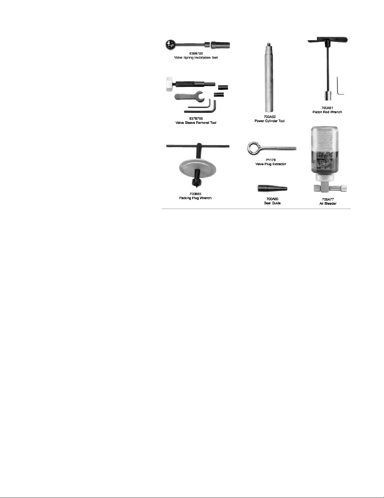
It is recommended that special assembly tools,
which can be ordered under part number
G701/G704KT, be used to overhaul this tool.
Virtually all of the moving parts in the tool ride on
O-rings, protected by back-up rings where high
pressure dictates. This means no metal-to- metal
wear. By use of close tolerances and low micro-inch
surfaces against which the O-rings seal, a long tool
life can be expected before any overhaul becomes
necessary. At that time, complete overhaul can be
achieved by the use of Service Kit G83KS which
contains a complete set of O-rings, back-up rings,
screws, washers and gaskets.
Not shown, but included: 701A67 Seal
Guide, 702B62 Power Cylinder Tool, 703A53
Seal Guide, 702A64 Seal Guide.
AIR VALVE
To disassemble:
Disconnect riveter from the air source.
Remove retaining ring (12) and muffler (11). Insert a valve plug extractor (P1178) or 5/16-18 threaded rod or bolt into end of valve plug
(10) and pull it out. Using the same procedures, pull out spool assembly (72).
NOTE: It should never be necessary to remove valve sleeve (3) unless the ports become plugged from contaminated air.
If it is suspected that the ports are plugged, use needle nose pliers to grasp end of spring (4), turn clockwise and pull
to dislodge from groove in handle. With spring removed, valve sleeve (3) can be pulled out using an 837B700
valve sleeve removal tool.
To re-assemble:
Reverse the above procedure making sure that all O-rings are properly lubricated. To avoid damaging the O-rings (2), carefully install
sleeve (3) with your fingers. Gently push and wiggle sleeve to allow O-rings to slip past inner ports. Spring (4) is best installed using tool
836B700 to push the large diameter coil into the groove. Caution: the riveter cannot operate if the spring is not anchored firmly.
HEAD SUB-ASSEMBLY
Always remove the complete pulling head from the tool before attempting disassembly of the head assembly.
Remove end cap (60). Push against threaded end of head piston (54) and slide it out of head cylinder (51). Be careful not to
damage threads or cause burrs on polished piston rod surface.
O-ring (52), back-up rings (53) then O-ring (57), back-up ring (58) can be removed using a bent hook.
If the head piston does not return fully forward after the tool has been fully overhauled although it is properly bled, it may be
necessary to remove and service the pressure relief valve sub-assembly (74).
Remove the pressure relief valve sub-assembly (74) from the head cylinder (51). Remove the O-ring (48) from the head
cylinder (51). If damaged, replace. Carefully unscrew the ball seat (45) from the spring seat (42) using soft jaws. The threads
of this part have had Loctite®242 applied. When all components have been removed, clean and dry thoroughly. If the spring
(43) appears to have a “set”, replace it. This pressure relief valve should hold 1200 psi (82.7 bar) before opening.
To re-assembly reverse the above procedure. Apply a small amount of Loctite®242 on the smaller thread size of the spring
seat (42). Allow 30 to 60 minutes for the Loctite®to cure. Before installing the valve sub-assembly back into the head cylinder,
make sure the O-ring, (48) is seated concentrically inside of the valve cavity.
Always lubricate all O-rings with Lubriplate® 630A. The re-assembly sequence is the opposite of disassembly. This includes filling
the handle (1) with oil before replacing gasket (70) and O-ring (69), just prior to replacing the head sub-assembly onto the handle.
Tighten the four socket head cap screws (71) uniformly to prevent leakage around the gasket. When assembled, purge system of
air by following the “Fill and Bleed instructions” on page 4.
THE G701/G704KT TOOL KIT

6
HANDLE SUB-ASSEMBLY
To inspect air cylinder bore, remove parts (34) through (38). Any further disassembly will require removal of the
head assembly.
For complete disassembly, start by removing parts (34) through (38). Holding the tool upright, remove four socket head cap
screws (71). Lift head assembly from handle (1) and set aside O-ring (69) and gasket (70). Empty all oil into a container by
pouring from handle. Dispose of oil according to environmental regulations.
Place piston rod wrench (700A61) into the top of the handle, into the hex socket in the head of the piston rod cap (16). While
holding this wrench, remove locknut (33) using the 7/16" socket in the packing plug wrench (700B65). Still holding piston rod
wrench, remove air piston (31) using packing plug wrench (700B65), by turning counterclockwise. When air piston is completely
freed from piston rod, tap or push on the piston rod wrench to eject piston from bottom of handle.
After removal of air piston, slide piston rod (13) back up to the end of its travel. Using packing plug wrench (700B65), remove
packing plug (27). It may be necessary to hold handle upside down in a vise while loosening packing plug. With packing plug
removed, power cylinder (20) can be tapped out by lowering power cylinder tool (700A62) down into top of handle onto top of
cylinder. The O-rings and back-up rings (24) and (25) are best removed and replaced by using a thin bent hook.
To re-assemble the handle, reverse the above procedure, being certain that all the O-rings are properly lubricated
before installation.
Attach the seal guide (700A60) to the piston rod (13) and with a mallet, tap the piston rod through the packing plug (27).
Place air piston (31) into handle bore. Important: Be sure that the radial pattern embossed side of the air piston is facing
downwards toward the smaller washer (30) with the smooth side of the air piston facing you.
Place the larger washer (32) over the threaded shaft, with the counterbored side toward the air piston.
To finish the air piston assembly, thread the locknut (33) onto the piston rod.
Most important, to prevent damage to piston threads, the above assembly instructions must be followed and the locknut
tightened between 50 in.-lb. (5.65 N-m) and 59 in.-lb. (6.67 N-m) of torque.
PULLING HEADS
Pulling heads are not furnished and must be ordered separately. Make certain the nose assembly is kept clean, especially around
the riveting end, as adhesives, chips, sealants, etc., will clog up the serrations of the jaws and may cause slippage of the stem.
Please refer to the pulling head charts below for the proper selection. All Huck nose assemblies suitable for the 352 and 230 style
tools will fit directly on this tool.
Note:
A 5/16” Hex is formed on the riveter head piston to allow tightening of the collets. Insert an Allen wrench into stem deflector to hold
head piston while tightening collet.
BASIC PULLING
HEAD NO. SWIVEL NOSE
PULLING HEAD NO.
SWIVEL NOSE
SELF-RELEASING
PULLING HEAD NO.
SWIVEL NOSE,
SELF-RELEASING
CHISEL SHAPE NOSE
PULLING HEAD NO. LOCKBOLT
DIA.
STRAIGHT
PULLING
HEADS
H513-04-20
H513-04-35
H513-04-60
-04
H513-05-35
H513-05-60 H513S-05-20 H513SR-05-20
H513SRC-05-20
H513SRC-05-35 -05
H513-06-20
H513-06-60 H513S-06-20
H513S-06-35 H513SR-06-20
H513SR-06-35 H513SRC-06-20
H513SRC-06-35 -06
H513-08-35* H513S-08-35
-08
OFFSET
PULLING
HEADS
H563-5B
H563-6B
H563 SP-5B
H563 SP-6B
-05
-06
-05
-06
NOTES:
1. No letter after P/N indicates basic head.
2. “S” after basic P/N indicates swivel nose.
3. “SR” after basic P/N indicates swivel nose, self-releasing.
4. “SRC” after basic P/N indicates swivel nose, self-releasing, chisel shape nose.
5. Straight Lockbolt pulling head Part Numbers indicate pulling head length when attached to the G83.
Example: Part No. H513-04-20 indicates the pulling head extends 2.0" beyond gun line.
6. *Installs Aluminum Lockbolt Only.

7
G83 PULLING HEAD SELECTION CHART
MAXIBOLT PULLING HEADS
CHERRYMAX® ADAPTER AND PULLING HEADS
PULLING
HEAD PART NO. CHERRYMAX®
DIAMETER ADAPTER
STRAIGHT H701B-456 -4, -5, -6 744-300
H781-456 -4, -5, -6 744-300
H782 -4, -5, -6 744-300
RIGHT ANGLE H753A-456 -4, -5, -6 744-300
OFFSET
H513SRC-06-35 STRAIGHT PULLING HEAD
The H513 series pulling heads are available to accommodate the 1/8" diameter through 1/4" diameter lockbolts in varying lengths.
The pictured head assembly is swivel-nose, self-releasing, chisel nose with a length of 3.5 inches from the riveter line.
FOR MOUNTING AND OPERATING INSTRUCTIONS SEE PULLING HEAD TOOL SHEETS.
PULLING
HEAD MAXIBOLT
DIAMETER ADAPTER
-5
-6
-5 & -6 MB Plus
-5 744-200
-6 744-200
H84B-568
N/ASTRAIGHT
H828-5MB
H828-6MB
RIGHT
ANGLE
PART NO.
H83B-5MB/5MBU
H83B-6MB/6MBU
8
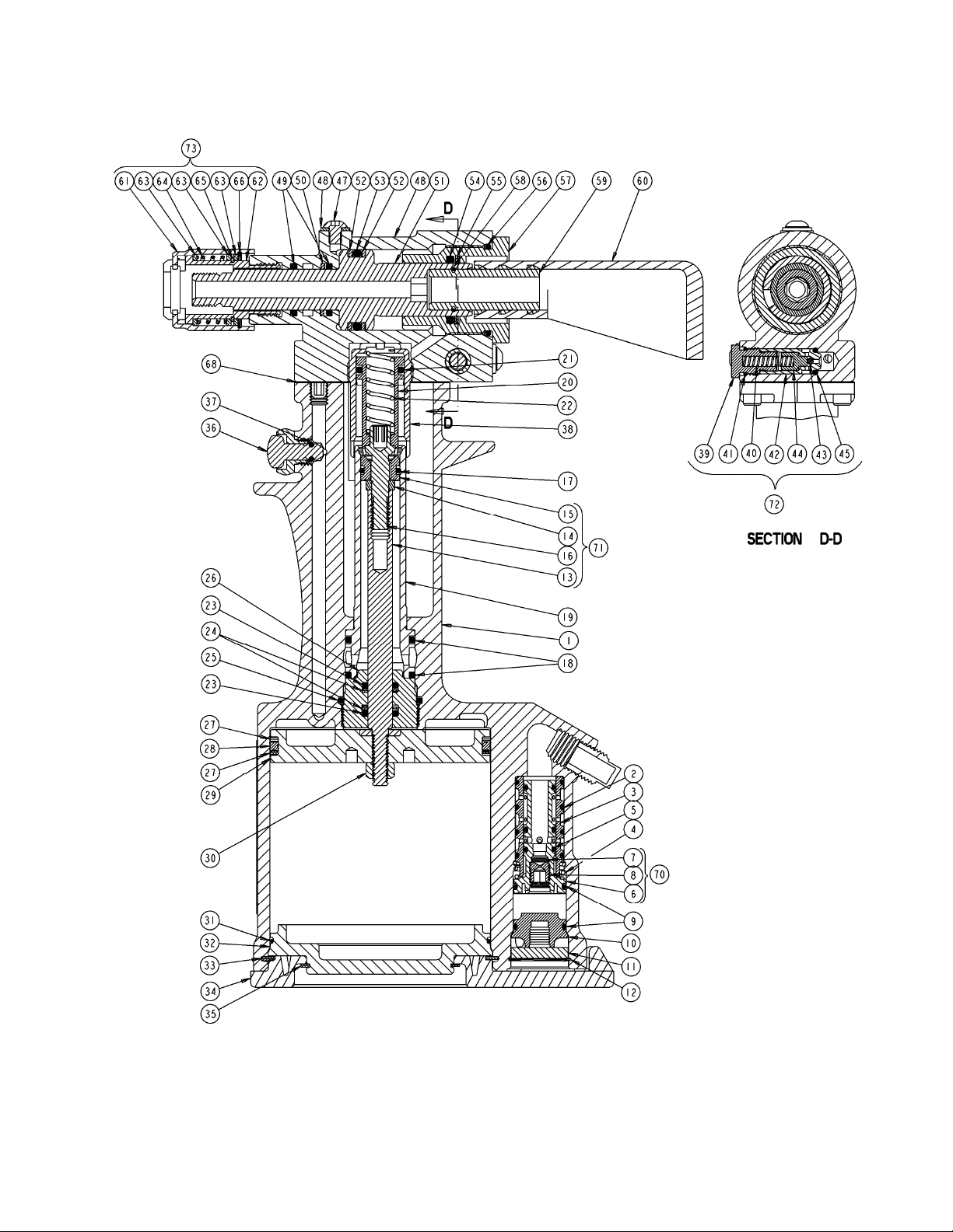
CROSS SECTION OF G83
THIS TOOL IS OBSOLETE; SEE G83A FOR REPLACEMENT
9
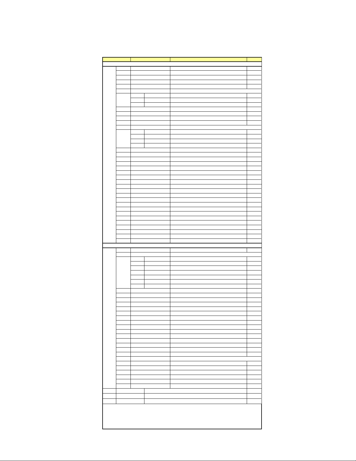
PART LIST FOR THE G83 (700-200) LOCKBOLT POWER TOOL ASSEMBLY
THIS TOOL IS OBSOLETE; SEE G83A FOR REPLACEMENT
ITEM NO. PART NUMBER DESCRIPTION QTY
700-216 SUB-ASSEMBLY, HANDLE
1 700-229 HANDLE, MACHINED 1
2 P-653 O-RING (.691, .551, .070) 4
3 700B73 SLEEVE, VALVE 1
4 700A67 SPRING 1
5 P-829* O-RING, DISOGRIN (.504, .364, .070) 3
70 700A15 SUB-ASSEMBLY, VALVE SPOOL
6 700D15-2 SPOOL, VALVE 1
7 700A18 FILTER, AIR VALVE 1
8 700A69 SCREW, METERING 1
9 P-834* O-RING, DISOGRIN (.816, .676, .070) 2
10 700A16 PLUG, VALVE 1
11 700A17 MUFFLER 1
12 P-279 RING, RETAINING (INT..906 DIA.) 1
71 700-219 POWER PISTON & ROD SUB-ASSEMBLY
13 700A10** ROD, POWER PISTON 1
14 702A12** STOP, PISTON 1
15 700B118** PISTON, POWER 1
16 700-202** CAP, PISTON ROD 1
17 P-830 O-RING (.629, .489, .070) 1
18 P-833 O-RING (1.068, .862, .103) 2
19 700C122 CYLINDER, POWER 1
20 700-205 PISTON, RETURN 1
21 P-508 O-RING (.755, .549, .103) 1
22 P-1367 SPRING 1
23 P-838* O-RING, DISOGRIN (.568, .362, .103) 2
24 P-115 RING, BACK-UP (.551, .375, .088) 2
25 P-727 O-RING (1.318, 1.112, .103) 1
26 700B93 PLUG, PACKING 1
27 P-731 RING, BACK-UP (3.365, 3.125, .120) 2
28 P-730 RING, QUAD (3.387, 3.109, .139) 1
29 700B6 PISTON, AIR 1
30 P-737 NUT, CONELOK, 1/4-20 1
31 P-725 O-RING (3.129, 2.989, .070) 1
32 700B4 BASE, HANDLE 1
33 P-735 RING, RETAINING (INT. 3.500 DIA.) 1
34 700B109 COVER, BASE 1
35 P-736 RING, RETAINING (EXT. 2.250 DIA.) 1
36 703A33 ASSEMBLY, TRIGGER (INCLUDES P-223) 1
37 P-223 O-RING (.285, .145, .070) 1
700-213 SUB-ASSEMBLY, HEAD CYLINDER
38 700-204 CYLINDER, RETURN 1
72 700-214 SUB-ASSEMBLY, RELIEF VALVE
39 700-218 SEAT, SPRING 1
40 P-1366 SPRING 1
41 P-383 O-RING (.441, .301, .070) 1
42 700-215 SEAT, BALL 1
43 P-688 BALL (3/32 DIA.) 1
44 700-217 PISTON, VALVE 1
45 P-111 O-RING (.379, .239, .070) 1
46 P-573 SCREW, BUTTON HD CAP, 10-32 X 1/4 3
47 P-572 STAT-O-SEAL (.430, .180, .125) 3
48 700-203 CYLINDER, HEAD 1
49 P-568 O-RING (.818, .612, .103) 2
50 P-242 RING, BACK-UP (.801, .625, .088) 1
51 700-210 PISTON, HEAD 1
52 P-932 RING, BACK-UP (1.242, 1.000, .121) 2
53 P-113 O-RING (1.262, .984, .139) 1
54 P-107 O-RING (1.074, .796, .139) 1
55 P-108 RING, BACK-UP (1.054, .812, .121) 1
56 P-1373 O-RING (1.403, 1.171, .116) 1
57 700-212 CAP, END 1
58 P-880 RING, RETAINING, NON-STANDARD 1
59 703A13 FITTING, DEFLECTOR 1
60 530A16 DEFLECTOR 1
73 700-211 SUB-ASSEMBLY, ADAPTER
61 700-256 SLEEVE, LOCKING 1
62 700-255 EXTENSION, HEAD 1
63 700-257 SPACER, ADAPTER 3
64 P-1372 SPRING 1
65 P-957 RING, RETAINING (EXT Ø.875) 1
66 P-699 RING, RETAINING (INT Ø1.125) 1
67 P-832* O-RING, DISOGRIN (.379, .239, .070) 1
68 700-230 GASKET 1
69 P-27 SCREW, SOCKET HEAD CAP, 8-32 X 1/2 4
*No substitutions.
** Not sold separately
*** Included in Air Piston Kit 700A115

10
EXPLODED VIEW OF G83
THIS TOOL IS OBSOLETE; SEE G83A FOR REPLACEMENT

For more information
p
lease contact our Technical Services De
p
artment at Tel. 714-850-6022
1224 East Warner Ave,
Santa Ana, CA 92705
Tel: 1-714-545-5511
Fax: 1-714-850-6093
www.cherryaerospace.com
© 2015 Cherry Aerospace
Seller warrants the goods conform to applicable specifications and drawings and will be manufactured and inspected according to generally accepted practices of
companies manufacturing industrial or aerospace fasteners. In the event of any breach of the foregoing warranty, Buyer’s sole remedy shall be to return defective
goods (after receiving authorization from Seller) for replacement or refund of the purchase price, at the Seller’s option. Seller agrees to any freight costs in
connection with the return of any defective goods, but any costs relating to removal of the defective or nonconforming goods or installation of replacement goods
shall be Buyer’s responsibility. SELLER’S WARRANTY DOES NOT APPLY WHEN ANY PHYSICAL OR CHEMICAL CHANGE IN THE FORM OF THE
PRODUCT IS MADE BY BUYER.
THE FOREGOING EXPRESS WARRANTY AND REMEDY ARE EXCLUSIVE AND ARE IN LIEU OF ALL OTHER WARRANTIES AND REMEDIES;
ANY IMPLIED WARRANTY AS TO QUALITY, FITNESS FOR PURPOSE, OR MERCHANTABILITY IS HEREBY SPECIFICALLY DISCLAIMED AND
EXCLUDED BY SELLER. THIS WARRANTY IS VOID IF SELLER IS NOT NOTIFIED IN WRITING OF ANY REJECTION OF THE GOODS WITHIN ONE
(1) YEAR AFTER INITIAL USE BY BUYER OF ANY POWER RIVETER OR NINETY (90) DAYS AFTER INITIAL USE OF ANY OTHER PRODUCT.
Seller shall not be liable under any circumstances for incidental, special or consequential damages arising in whole or in part from any breach by Seller, AND SUCH
INCIDENTAL
,
SPECIAL
,
OR CONSE
Q
UENTIAL DAMAGES ARE HEREBY EXPRESSLY EXCLUDED.
Declaration of Conformity
We, Cherry® Aerospace, 1224 E. Warner Ave., Santa Ana, CA 92705
declare under our sole responsibility that the product
type G83
Serial No.-
to which this declaration relates is in conformity with the following standards
EN292 part 1 and part 2
ISO 8662 Part 1
ISO 3744
following the provisions of the Machine Directive 89/392/EEC
(as amended by Directive 91/368/EEC) and 93/68/EEC
Santa Ana, CA -
date of issue
Original certification and signatures on file
TM-G83
Rev.: E
DCR# 15-0393
Date: 04/30/15
Supplier’s Federal Identification Code: 11815
WARRANTY
LOCTITE
®
is a registered trademark of Henkel Corporation
DEXRON®is a registered trademark of GM corporation.
PARKER®is a trademark of Parker Hannifin Corporation
LUBRRIPLATE®is a trademark of Fiske Brothers Refining Co.
This manual suits for next models
1
Table of contents
Other Cherry Aerospace Power Tools manuals


