Cherry Aerospace CHERRYLOCK G695B User manual

TM-G695B Rev.: D DCR# 16-0786 DATE: 10/13/16 Federal Identification Code: 11815 © 2016 Cherry Aerospace
1
Original Instructions
G695B
RIGHT ANGLE, DOUBLE ACTION
CHERRYLOCK®POWER TOOL

TM-G695B Rev.: D DCR# 16-0786 DATE: 10/13/16 Federal Identification Code: 11815 © 2016 Cherry Aerospace
22
LOCTITE® is a registered trademark of Henkel Corporation
DEXRON®is a registered trademark of GM Corporation.
PARKER®is a trademark of Parker Hannifin Corporation
LUBRRIPLATE®is a trademark of Fiske Brothers Refining Co.
THE G695B DOUBLE ACTION
RIGHT ANGLE RIVETER
TABLE OF CONTENTS
Description ........................................................................................................................................................................................ 3
Technical Specifications .................................................................................................................................................................... 3
Putting the Tool in Service................................................................................................................................................................. 3
Warranty Information ......................................................................................................................................................................... 3
General Operation Safety Warnings .................................................................................................................................................. 4
Operating Instructions ....................................................................................................................................................................... 5
Fastener / Pulling Head Selection......................................................................................................................................... 5
Installing H690 pulling head................................................................................................................................................... 5
Pulling Head Adjustment................................................................................................................................................. 5
Lock ring Anvil Setting Adjustment........................................................................................................................... 6
Shift Point Setting........................................................................................................................................................ 6
Riveter Repair and Maintenance ....................................................................................................................................................... 6
Tools and Service Kits Needed .............................................................................................................................................. 7
Service Procedure................................................................................................................................................................... 7
Head Cylinder Subassembly ......................................................................................................................................... 7
Power Handle Subassembly ......................................................................................................................................... 7
Air Valve Subassembly ................................................................................................................................................. 7
Component List....................................................................................................................................................................... 8
Exploded View ....................................................................................................................................................................... 9
Priming the Hydraulic System .............................................................................................................................................. 10
Recommended Hydraulic Fluids .................................................................................................................................. 10
Fluid Handling Safety .................................................................................................................................................. 10
Bleeding Instructions.................................................................................................................................................... 10
Troubleshooting Guide..................................................................................................................................................................... 11

TM-G695B Rev.: D DCR# 16-0786 DATE: 10/13/16 Federal Identification Code: 11815 © 2016 Cherry Aerospace
33
DESCRIPTION
The Cherry® G695B
riveter is a compact, right
angle riveter designed for
high productivity, reliable
installation of the short
grip double action
Cherrylock®fasteners (NAS1738 / NAS1739 bulb and NAS1398 /
NAS1399 wiredraw types).
The pulling heads (H690 Series) are not furnished with this tool and must
be ordered separately.
.
TECHNICAL SPECIFICATIONS
Cherry®Aerospace (CHERRY®) policy is one of continuous
development.
Specifications shown in this document may be subject to change
which may be introduced after publication. For the latest
information always consult CHERRY®.
AIR PRESSURE 90 to 110 PSI (6.2 to 7.6 bar)
STROKE 5/8 inch (15.8 mm)
PULLING-FORCE: 2000 lbs @ 90 psi
(8.9 kN @ 6.2 bar)
PUTTING THE TOOL IN SERVICE
Connect the tool to a dedicated line of clean air equipped with a pressure
regulator.
If necessary, a preset inline pressure regulator may be purchased and
mounted at the air inlet of the riveter (P1505, sold separately).

TM-G695B Rev.: D DCR# 16-0786 DATE: 10/13/16 Federal Identification Code: 11815 © 2016 Cherry Aerospace
4
SAFETY WARNINGS
•Wear proper PPE(Personal Protection equipment) when operating, servicing or repairing this tool
•Read Manual; operators must be trained in safety and correct tool operation
•Service and repairs shall be performed only by trained personnel.
•Do not pull rivet in the air or directed at any person.
•Do not use the tool with a damaged or missing stem deflector
•Make sure that the air muffler is not obstructed and is directed away from people.
•Do not exceed the recommended air pressure.
To ensure safety, use the pre-set air pressure regulator P/N P1505.
•Make sure to disconnect from the air supply before service or repair.
•Wash thoroughly after handling hydraulic fluid.
•Unauthorized modifications, including using substitute components will void warranty and
shall be at the customer's entire responsibility.
•Do not use any substitutions as they will impact the tool safety and reliability life.
OPERATING INSTRUCTIONS
Before using the tool:
CAUTION
•Read the tool manual instructions; before first using the tool.
•Read and comply to all safety instructions given in this document in addition to the general safety rules applicable
•Make sure the tool is connected to an air source operating within the recommended pressure range
•Before installing the permanent fasteners, make sure that the structure is properly clamped with temporary fasteners
•Make sure that the correct pulling head is selected for the fastener to be installed and that the tool is in good working condition
Installing Fasteners: Place the fastener into the prepared hole then place the pulling head over its stem and depress the trigger.

TM-G695B Rev.: D DCR# 16-0786 DATE: 10/13/16 Federal Identification Code: 11815 © 2016 Cherry Aerospace
5
PULLING HEAD SELECTION FOR BLIND FASTENERS
•The lists given below are for reference only; for more up to date and detailed information, please check on the
Cherry Aerospace webpage as following: Installation Tooling Manuals(links to current tool manuals) and
Product Expert (interactive database for tool recommendations)
INSTALLING THE PULLING HEAD ON RIVETER
1. Place anvil (B) into nose piece (C)
2. Pry the bottom leaf spring open, with the help of a flat
screwdriver, far enough to insert the anvil and nose
assembly. Release the leaf spring and allow it to snap
over the nose assy.
3. Remove the set screw (20) and thread the jaw holder
assembly (A) into upper frame (using flat wrench
690A62 included with tool) to about 1/16” protrusion
behind the upper frame.
4. Thread screw (20) back in without tightening; the pulling
head must be adjusted following the directions below.
5. In case an extension nose piece is being used (for example P/N H690-4C-15/16”) there is an additional part
(ring, shown in dotted line). This ring must be placed on top of the anvil (B) / nose piece assembly before
being placed into the leaf spring.
In this case, is advisable in this case to loosen the screws holding the leaf spring rather than forcing it open.
PULLING HEAD ADJUSTMENT
6. Prior to installing fasteners, the pulling head must be setup using the setup gages provided with the riveter.
The gages are color coded as following:
•Green for the -4 diameter, (P/N 628-4)
•Red for the -5 diameter (P/N 628-5)
•Blue for the -6 diameter (P/N 628-6)
•No color for the -8 diameter (P/N 628-8)
BULB TYPE CHERRYLOCK FASTENERS (NAS1738 & NAS1739)
RIVET
DETAILS
MATERIAL
ALUMINUM
MONEL
HEAD
STYLE
UNIVERSAL FLUSH UNIVERSAL FLUSH
BASE PART
NUMBER
CR22239
CR22238
CR2539
CR2538
CR2249
CR2248
PULLING
HEAD
PART
NUMBER
RIVET
DIA. CODE THIS TOOL INSTALLS UP
TO THE FOLLOWING GRIP CODE
H690-4
-4
ALL GRIPS
ALL GRIPS
ALL GRIPS
ALL GRIPS
H690-5
-5
ALL GRIPS
ALL GRIPS
ALL GRIPS
ALL GRIPS
H690-6 -6 - - - -
WIREDRAW TYPE CHERRYLOCK FASTENERS (NAS1398 & NAS1399)
RIVET
DETAILS
MATERIAL
ALUMINUM
MONEL
STAINLESS STEEL
HEAD
STYLE
UNIVERSAL FLUSH UNIVERSAL FLUSH UNIVERSAL FLUSH
BASE PART
NUMBER
CR2163 CR2162 CR2643 CR2642
CR2263
CR2262
CR2563
CR2562
CR2653
CR2652
CR2663
CR2662
PULLING
HEAD
PART
NUMBER
RIVET
DIA. CODE THIS TOOL INSTALLS UP TO THE FOLLOWING GRIP CODE
H690-4
-4
-04
-04
-04
-04
-04
-04
H690-5
-5
-04
-04
-04
-04
-04
-04
H690-6
-6
-04
-04
-04
-04
H690-8 -8 -04 -04

TM-G695B Rev.: D DCR# 16-0786 DATE: 10/13/16 Federal Identification Code: 11815 © 2016 Cherry Aerospace
6
LOCKRING ANVIL SETTING ADJUSTMENT
Note: All the item numbers refer to the exploded view from page 10.
1. Insert the short end of the setup gage into the nosepiece (C).
2. Loosen the Jam Nut (item 29) so set screw (item 28) can be
adjusted.
3. Thread the set screw (item 28) in or out until top of the gage is
flush with the gaging surface
4. Tighten the Jam Nut (item 29) while holding the Set Screw
(item 28) to prevent it from rotating.
SHIFT POINT SETTING
Before starting this set-up, make sure that the set screw (20) is loose.
1. Select the appropriate diameter gage and push the long, serrated end into the nosepiece (C); if the gage
falls freely,
2. Unthread (turn counter-clockwise) the jaw holder (A) with tool 690A62, until the gage pin get stuck inside the
nosepiece
3. Loosen the grip slightly by threading the jaw holder (A) in (turn clockwise) about a quarter turn.
4. Tighten the set screw (20).
To verify setup, install fasteners in a test plate; the fastener stems should break relatively flush with the top of
the rivet (see applicable procurement specifications). If high or low stem protrusion is observed, loosen the set
screw (20) and turn the jaw assembly holder (A) one-quarter of a turn at a time, in either direction, until desired
flushness is obtained. The position of the anvil (see above procedure) may also need to be fine-tuned.
RIVETER REPAIR AND MAINTENANCE
This riveter has been manufactured to give maximum service with minimum care.
In order to keep the tools in optimum operating condition, it
is advisable to set-up a Preventive Maintenance check list
including, at a minimum, the following:
•Visually inspect the tool to make sure it is in good working
condition and there are no fluid leaks
•Make sure the tool is bled regularly (page 12)
•Check the service sticker due date; service the tools on a
regular basis.
Should repair or service be necessary, follow the instructions given below.
CAUTION
•Read the tool manual instructions; it is advised that repair is conducted only by properly trained
personnel.
•Make sure the air is disconnected.
•Protect the sealing surfaces to avoid damage.
Tools and Service Kits Needed
•Make sure that the proper service kit (ordered separately) and tools are available.
oSERVICE KIT: G695KS –contains Springs, Seals, O-Rings and Back-up Rings
oTOOLS: G85KT – tool kit and a Needle Nose Pair of Pliers

TM-G695B Rev.: D DCR# 16-0786 DATE: 10/13/16 Federal Identification Code: 11815 © 2016 Cherry Aerospace
7
SERVICE PROCEDURE
HEAD SUBASSEMBLY
Disassembly Instructions:
•Remove the bleed screw (38) and drain the fluid.
•Loosen set screw (20) and remove the pulling head.
•Remove the screws (26) and the sides (17) and push out the pins (23 and 41).
This will allow frames (19 and 40) to fall free and rocker arm (24) may then be lifted out.
•Remove the screws (12) from top and bottom of the cylinder the remove the springs, spacers, and limit bars (13, 14, 15, 16 & 39)
•Unscrew the cap (9) and pull on the cam (11); remove the set screw (10) first should removing the cam from the piston (4) be
necessary
Assembly Instructions:
•Build the cylinder assembly first; assemble items (1) through (11) making sure the set screw (10) is tight against piston rod (4).
•Place frames (19 and 40) one on top of the other; they should fit together with no warping.
•Install rollers (18) in upper frame (19), using pin (23).
•Install bearings (22) in rocker arm (24), using pin (21) and install rollers (18) in lower frame (40), using pins (30).
•Place sleeve (25) in the large hole of the lower frame (40).
•Install the rocker arm (24) in the lower frame (40), using pin (23).
•Thread the adjustment-screw (28) in through the lower frame (40) and secure it with jam nut (29).
•Slide the lower frame (40) over cylinder assembly (36) making sure that cam (11) is in the correct position with the flat section at the
bottom as shown in sketch. Insert pin (41) through frame and through bottom hole in cylinder (36).
•Slide the upper frame (19) over the cylinder assembly (36) and hold in place with pin (41).
•Place sides (17) over the frames (19 and 40) and secure with screws (26), using washers (27) over the front two screws, between the
sides and the frames, for clearance.
•Attach leaf springs (39 and 16), spacer (14), and limit bar (13) starting with lower frame, using the screws (12).
Note: Leaf spring (39) should be all the way forward and aligned with large hole in lower frame. Repeat this operation with upper
frame. Make sure that all hoses and fittings are connected properly as shown in the exploded view.
POWER HANDLE SUBASSEMBLY
Disassembly Instructions:
•Remove the Manifold (49) and set it aside
•Drain all the fluid, then turn up-side down and remove the screws holding the bottom cover (87);
•Push the power piston all the way down, remove the cotter pin (82) and unthread the locknut (81) and then remove the air piston (80)
by using wrench 530A86 and a 9/16” socket wrench; hold the top of the piston with tool 530A86 to prevent it from turning. When
completely unthreaded, insert the thread end of too 530A88 into the bottom of air piston (80) and using it as a handle, pull the piston
out
•Remove packing plug (77) with the help of wrench 530A83 and a 1-1/16” socket wrench.
•Tap the power cylinder (70) from the top (use tool 530A88); when loosened, it will fall through the bottom of the handle.
•Remove all the seals and inspect all components for wear. Replace all seals and worn components
Assembly Instructions:
•The re-assembly sequence is the opposite of disassembly; to prevent damage to piston threads; suggested tightening torque for the
locknut (37) between 50 and 59 in-lb (5.65 and 6.67 N-m).
•After service, the riveter must be primed and bled (page 12)
AIR VALVE SUBASSEMBLY
Disassembly Instructions:
•Remove retaining ring (69) and muffler (68).
•Pull out the valve plug (67) and the Valve Spool (65) with the help of extractor P1178;
•Dislodge and pull the spring (63) out using needle-nose pliers
•In the unlikely event that you want to pull the Valve Sleeve (62), use the tool 837B530 (internal expansion collet).
Assemble Instructions:
•Replace all O-Rings and apply an O-ring lubricant (Parker® silicone lube or equivalent).
•To re-assemble, reverse the procedure given above; snap the Spring (63) into its groove with the help of tool 836B530

TM-G695B Rev.: D DCR# 16-0786 DATE: 10/13/16 Federal Identification Code: 11815 © 2016 Cherry Aerospace
8
G695B – COMPONENT LIST
REF
PART
DESCRIPTION
QTY.
REF
PART
DESCRIPTION
QTY.
1 P604 O-Ring 1
46 P463 Pipe Plug Dryseal 1
2 P603 Back-Up Ring 1
47 P225 Button Hd. Soc. Screw 1
3 P528 O-Ring 1
48 P670 Stat-O-SeaI 1
4 690A157 Piston 1
49 680A37-3 Manifold Assembly 1
5 690A8 Piston Spring 1
52
530A60 Power Piston & Rod Assembly 1
6 690A26 Stop 1
50
P209 Back-Up Ring 2
7 P921 O-Ring 1
51
P216 Quad Ring 1
8 P690 O-Ring 1
53 P194 O-Ring 1
9 690A29 Cap 1
54 530B8 Gasket 1
10 P842 Set Screw 1
55 530A113 Button Head. Cap Screw 1
11 690A105 Cam 1
56 530A146 Handle 1
12 P710 Button Head. Screw 4
57 P64 Socket Head. Cap Screw 6
13 690A60 Limit Bar 2
58 530A35 Swivel Bolt 1
14 690A61 Spacer 2
59 P195 0-Ring 2
15 690A25 Leaf Spring 1
60 530A34 Swivel 1
16 690A24 Leaf Spring 2
61 P848 0-Ring 4
17 690B114 Side 2
62 530B179 Valve Sleeve 1
18 690A156 Roller 4
63 590A178 Spring 1
19 690C103 Upper Frame 1
64 P701 O-Ring 3
20 P924 Soc. Hd. Set Screw 1
65 530B143 Spool Valve 1
21 690A23 Rear Bearing Pin 1
66 P244 O-Ring 2
22 P547 Roller Bearing 2
67 530A144 Valve Plug 1
23 690A121 Upper Bearing Pin 2
68 530A145 Muffler 1
24 690C104 Rocker Arm 1
69 P699 Retaining Ring 1
25 690A30 Sleeve 1
70 530A13B Power Cylinder 1
26 P413 Soc. Hd. Screw 4
71 P218 Quad Ring 2
27 P366 Washer 2
72 P204 Retaining Ring 2
28 P402 Set Screw 1
73 530A21-3 Washer 2
29 P923 Jam Nut 1
74 P213 Back-Up Ring 4
30 690A122 Lower Bearing Pin 2
75 P215 Quad Ring 2
33 690A 113 Handle 1
76 P196 O-Ring 1
34 703A33 Trigger Assembly 1
77 530B14 Packing Plug 1
35 P223 O-Ring 1
78 P214 Back-Up Ring 2
36 690A158 Cylinder Assembly 1
79 P222 Quad Ring 1
37 P572 Stat-O-Seal 1
80 530B15 Air Piston 1
38 P573 Button Hd. Soc. Screw 1
81 P302 Slotted Nut 1
39 690B28 Leaf Spring 1
82 P301 Cotter Pin 1
40 690C102 Lower Frame 1
83 P537 Retaining Ring 1
41 690Al27 Frame Pin 2
84 530B92 Bonded Cushion 1
42 530A123-8 Oil Hose Assembly 1
85 P197 O-Ring 1
43 530A119-8 Air Hose Assembly 1
86 530C141 Handle Base 1
44 P579 Steel Bushing 2
87 P700 Flat Head Socket Cap Screw 6
45 P456 Hose Fitting 2

TM-G695B Rev.: D DCR# 16-0786 DATE: 10/13/16 Federal Identification Code: 11815 © 2016 Cherry Aerospace
9
G695B – Exploded View
TM-G695B Rev.: D DCR# 16-0786 DATE: 10/13/16 Federal Identification Code: 11815 © 2016 Cherry Aerospace
10
PRIMING THE HYDRAULIC SYSTEM
RECOMMENDED HYDRAULIC FLUID
The riveter is supplied with Dexron® III ATF type “A”.
COMPATIBLE ALTERNATE FLUIDS
•Automatic Transmission Fluids: DEXRON IV, MERCON, Allison C4 or equivalent.
•Hydraulic Fluids: Hyspin® VG32 , Aeroshell fluid 4
CAUTION
•DO NOT MIX DIFFERENT TYPES OF HYDRAULIC OILS AND TRANSMISSION; HYDRAULIC AND TRANSMISSION
FLUIDS ARE NOT COMPATIBLE DIFFERENT TYPES OF FLUIDS MAY NOT BE COMPATIBLE WITH EACH OTHER.
•PHYSICAL PROPERTIES AND MATERIAL SAFETY DATA SHEETS FOR DIFFERENT FLUIDS MAY DIFFER FROM THE
ONE GIVEN BELOW, BUT THE SAFETY INFORMATION STILL APPLIES; CHECK WITH THE FLUID MANUFACTURER
FOR ADDITIONAL MSDS AND SPECIFIC PROPERTIES.
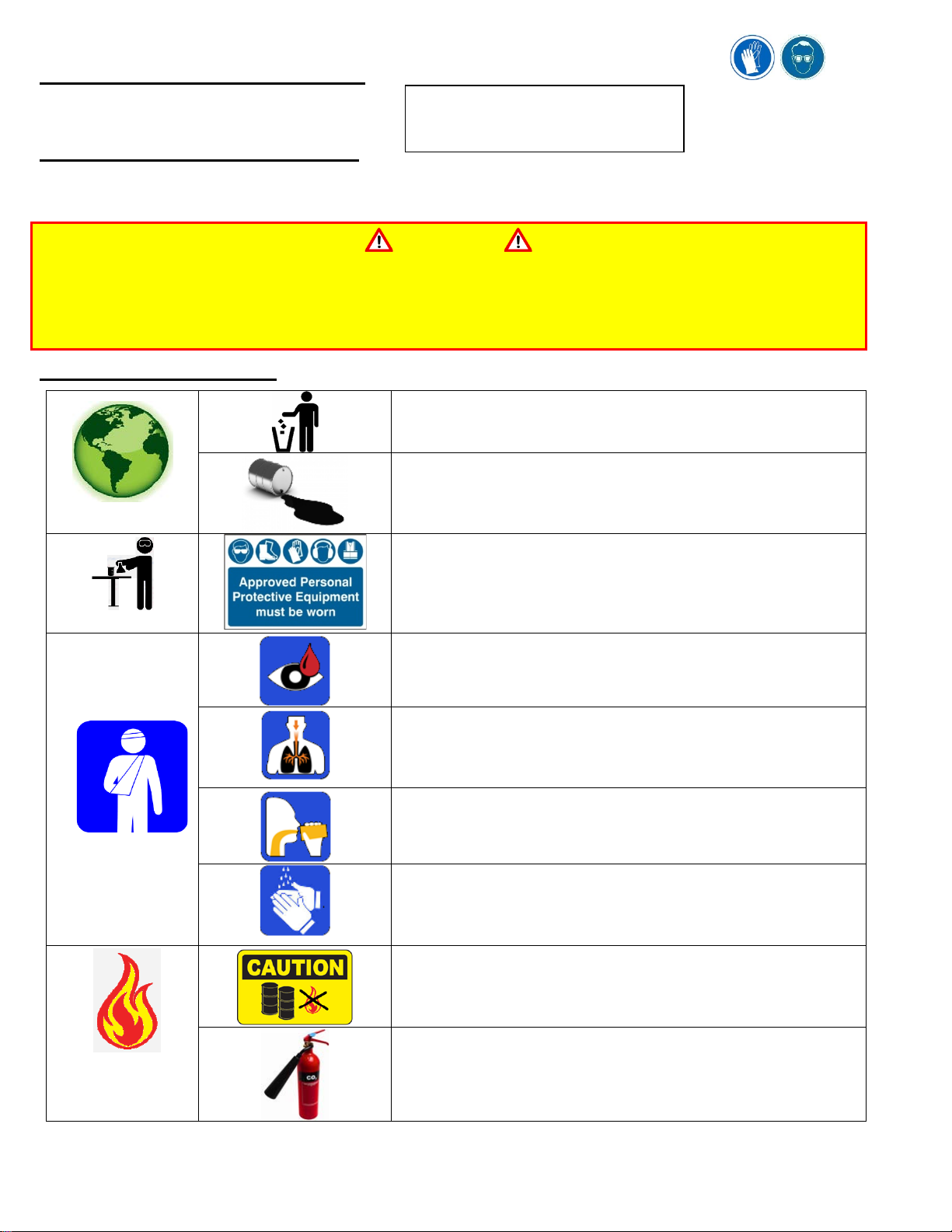
FLUID HANDLING SAFETY
ENVIRONMENTAL
•Waste Disposal in accordance with the applicable regulations
•Soak up spills with diatomaceous earth or other inert materials.
•Keep from drains, sewers and water courses.
•Filter and recycle used fluid; otherwise store and dispose of
according to the applicable regulations.
HANDLING
•Eye protection is required.
•Protective gloves, chemically resistant boots and apron are
recommended.
FIRST AID
•Flush eyes thoroughly with water.
•If irritation develops, consult a physician.
•To prevent inhalation, use in well-ventilated area.
•Short term exposure should pose no adverse health effects.
•If inhalation occurs, remove the affected person from the
contaminated area and apply artificial respiration if needed.
•DO NOT INDUCE VOMITING.
•Seek medical attention immediately.
In case of skin contamination:
•Wash thoroughly with soap and water as soon as possible.
•Brief skin contact requires no immediate attention.
•If irritation develops, consult a physician.
COMBUSTIBILITY
•It is slightly combustible when heated above flash point.
•It will release flammable vapors which can burn in open or be
explosive in confined spaces if exposed to source of ignition.
•Do not store near open flames or other sources of ignition.
•In case of fire, use only suitable extinguishing media:
CO2, dry powder, foam or water fog.
•CAUTION: DO NOT USE WATER JETS.
Specific gravity:
0.863
Weight per gallon:
7.18 lbs.
Open flash point:
>200°C (392°F)

TM-G695B Rev.: D DCR# 16-0786 DATE: 10/13/16 Federal Identification Code: 11815 © 2016 Cherry Aerospace
Seller warrants the goods conform to applicable specifications and drawings and will be manufactured and inspected according to generally accepted practices of
companies manufacturing industrial or aerospace fasteners. In the event of any breach of the foregoing warranty, Buyer’s sole remedy shall be to return defective
goods (after receiving authorization from Seller) for replacement or refund of the purchase price, at the Seller’s option. Seller agrees to any freight costs in
connection with the return of any defective goods, but any costs relating to removal of the defective or nonconforming goods or installation of replacement goods
shall be Buyer’s responsibility. SELLER’S WARRANTY DOES NOT APPLY WHEN ANY PHYSICAL OR CHEMICAL CHANGE IN THE FORM OF THE
PRODUCT IS MADE BY BUYER.
THE FOREGOING EXPRESS WARRANTY AND REMEDY ARE EXCLUSIVE AND ARE IN LIEU OF ALL OTHER WARRANTIES AND
REMEDIES; ANY IMPLIED WARRANTY AS TO QUALITY, FITNESS FOR PURPOSE, OR MERCHANTABILITY IS HEREBY SPECIFICALLY
DISCLAIMED AND EXCLUDED BY SELLER. THIS WARRANTY IS VOID IF SELLER IS NOT NOTIFIED IN WRITING OF ANY REJECTION OF
THE GOODS WITHIN ONE (1) YEAR AFTER INITIAL USE BY BUYER OF ANY POWER RIVETER OR NINETY (90) DAYS AFTER INITIAL USE OF
ANY OTHER PRODUCT.
Seller shall not be liable under any circumstances for incidental, special or consequential damages arising in whole or in part from any breach by Seller, AND
SUCH INCIDENTAL, SPECIAL, OR CONSEQUENTIAL DAMAGES ARE HEREBY EXPRESSLY EXCLUDED.
WARRANTY
PRIMING AND BLEEDING THE TOOL
After service, the riveter must be primed with hydraulic fluid before re-assembling the head
cylinder.
•Stand the base upright and fill the base handle (56) with fluid up to the top then
assemble and tighten the manifold.
•Stand the base upright with the hoses and head assembly above it and connect to an
airline. Caution: The tool will automatically trigger, so hold the head assembly firmly.
•Remove the screws (38) and (47) from cylinder (36) and manifold (49).
•Using a pressurized fluid source, circulate fluid until the it drains smoothly with no air
bubbles out of the bleed hole (where screw 38 was)
•Thread the screws back in and cycle the tool a few times to make sure it functions
properly.
•Redo this procedure if necessary to remove all the air pockets from the hydraulic fluid.
BLEEDING INSTRUCTIONS
This operation should be done as part of regular tool maintenance in order to replenish the
hydraulic fluid and remove the air bubbles from the hydraulic fluid.
What is needed:, an 1/8” Hex Key; 700A77 Bleed Bottle
•Place the hand held unit over an oil drip pan and remove the side Screw (38);
•Attach the Bleeder Bottle 700A77 and place the hand held unit in a vise making sure that
the bleeder bottle is upside down and it is the highest point of the system.
•Cycle several times; air bubbles from the system will be pushed up into bleed bottle,
being replaced by hydraulic fluid. Continue cycling until no more air bubbles are
released into the bottle.
•When done, carefully remove the bleed bottle and replace with Screw (38).
•Test for correct function; re-set if necessary.
TROUBLESHOOTING GUIDE
Should the riveter not operate properly,
1. Check that the tool is connected to an airline and the air pressure is within the recommended limits..
2. Bleed the system to eliminate air and replenish fluid.
3. Check for oil leakage.
a) Leakage around the cap screw (38) indicates that the screw is loose or the gasket (37) needs replacing.
b) Leakage through the by-pass hole at the base of the handle (56) indicate that the O-Rings (75) are worn or damaged.
4. Operate the trigger repeatedly to determine that it is working properly; this can be done by listening to the tool as the trigger is
depressed and released. If the valve is working properly the air piston (80) and power piston (52) can be heard traveling inside
the tool.
5. Check the piston stroke. If the tool is short of stroke, it may need to be serviced or at least bled properly.
6. Make sure the set screw (20) is tightened; if it gets lose, the jaw holder setting drifts during operation incapable of holding setup.
If the riveter still fails to operate properly, it may need to be serviced; we recommend contacting one of our authorized US or
international repair centers (http://cherryaerospace.com/contacts/distributors#tool-repair-us or
http://cherryaerospace.com/contacts/distributors#tool-repair-intl)
Table of contents
Other Cherry Aerospace Power Tools manuals


