19
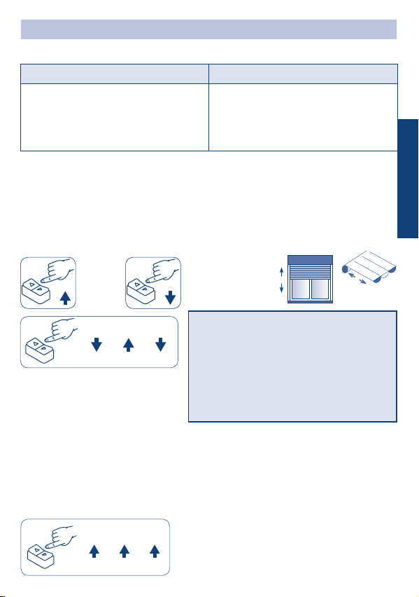
INSTRUCTION FOR USE IN MANUAL MODE
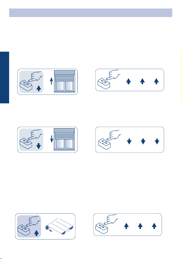
INSTRUCTION FOR USE IN MIXED MODE
COMAND SEQUENCES EXAMPLE
KEY TO SYMBOLS
UP DOWN
Press the
UP-button
Press the buttons quickly according to
the sequence indicated.
Press the
DOWN-button
DOWN DOWNUP
DOWN DOWN
UP
UP
UPUP UP
It is always possible to memorize limit switches of the rolling shutter/awning in mixed
mode, for example:
- Opening limit switch: automatic with mechanical blocks.
- Closing limit switch: manual with sequence on the button panel.
Most of the command sequences have three or six distinct steps.
The buttons must be pressed for less than 0.5 seconds as shown in the sequence, without
taking more than 1 second between one step and the next. If more than 1 second is taken,
the command is not accepted and the sequence must be repeated.
Command sequence example:
Attention! If the sequence requires a repetition
of the same commands (Up+Up/ Down+Down),
an interposition of the Stop position could be
necessary depending on the type of switch in use.
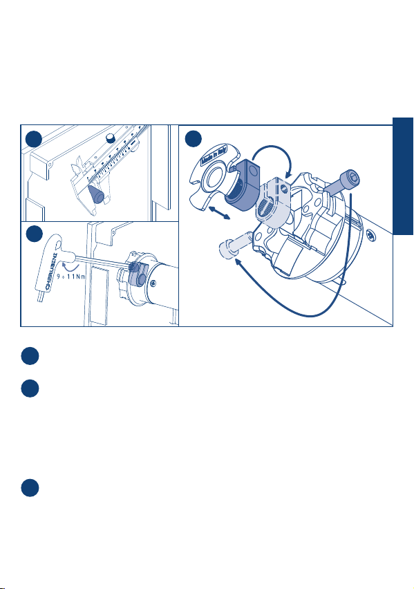
PLUG & PLAY Plus - WAVE WIRE
PLUG & PLAY Plus WAVE WIRE
In this mode the following devices are optional:
a) security locks or stiff xing springs,
b) xed or removable stoppers for end slats.
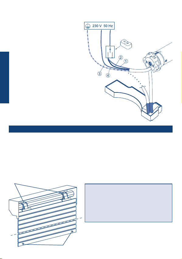
The motor Wave Wire is specic for use with
cassette awning: the upper limit switch (closing
position) can be set automatically. For other
types of awnings it’s possible to set both limit
switches manually.
PLEASE NOTE: Until both limit switch positions
have been memorized:
- PLUG & PLAY Plus at start up the motor
makes an initial brief movement with a 0.5
second delay and then it moves with a 0.5
second delay.
- Wave Wire at start up the motor moves with
a 0.5 second delay.
ENGLISH