Chesapeake & Midlantic BMT-70WAT User manual

Page 1of 4
INSTALLATION MANUAL –BMT-70WAT
Adjustable Wall Mount for Bosch™ Outdoor 6000 and 7000 Series Panoramic Cameras
WARNING: Before beginning installation of this product, carefully review the safeguards and precautions found on page 2 of this manual.
Unpacking
Unpack carefully. This is mechanical equipment and should
be handled with care. If an item appears to have been
damaged in shipment, replace it properly in its carton and
notify the shipper. If any items are missing, notify the
shipper. The shipping carton is the safest container in which
the unit may be transported. Save it for possible future use.
Service
If the unit ever needs repair service, the customer should
contact Chesapeake & Midlantic Marketing for a return
materials authorization (RMA) and shipping instructions.
Care and Maintenance
Perform routine maintenance to keep the unit dust free.
Model Designation
BMT-70WAT Wall Arm, Inverted, Adjustable, For Bosch
Outdoor 6000/7000 Series Panoramic
Cameras; White
Description
The BMT-70WAT accessory enables Bosch Outdoor 6000 and
7000 Series Panoramic Cameras (NDS-6004 and NDS-7004)
to be mounted to a wall and provide rotation and tilt
adjustment.
Hardware Kit
4 x Phillips Pan Head Screws
1 x 3/16” Allen Wrench
4 x Mounting Screws
4 x Plastic Wall Anchors
Tools Required
#2 Phillips Head Screwdriver/Bit
Certification
Camera installation should be performed by a licensed
professional and conform to the National Electrical Code
(NEC) and any applicable local codes.
Installation
1. Remove unit from packaging.
2. Hold mount up to installation side and use as a template
to mark mounting hole locations and cable entry hole
(see Figure 2).
3. Each fastener should have a minimum 200 lbs pull-out
strength. The mounting holes accept up to 1/4” diameter
fasteners. The mounting screws provided are not ideal
for all applications.
4. Feed wires through the mount, leaving enough slack to
route the cable through the housing to the camera.
5. Review the installation manual for the Bosch camera and
attach the camera to the mount accordingly using the
Phillips pan head screws from the mount’s hardware kit.
6. Adjust the mount to desired orientation; see Figure 2.
Figure 1
Rotation
adjustment
Tilt adjustment
Adapter Plate
Mounting Plate
from Bosch camera
Screws from mount
hardware kit
Bosch Camera
These Items
Sold Separately
Page 2of 4
IMPORTANT SAFEGUARDS
1. Read Instructions - All the safety and operating instructions should be read before the unit is operated.
2. Retain Instructions - The safety and operating instructions should be retained for future reference.
3. Heed Warnings - All warnings on the unit and in the operating instructions should be adhered to.
4. Follow Instructions - All operating and use instructions should be followed.
5. Cleaning - Unplug the unit from the outlet before cleaning. Do not use liquid cleaners or aerosol cleaners. Use a damp cloth for cleaning.
6. Attachments - Do not use attachments not recommended by the product manufacturer as they may cause hazards.
7. Accessories - Do not place this unit on an unstable stand, tripod, bracket, or mount. The unit may fall, causing serious injury to a person and serious
damage to the unit. Use only with a stand, tripod, bracket, or mount recommended by the manufacturer or sold with the product. Any mounting of the
unit should follow the manufacturer's instructions and should use a mounting accessory recommended by the manufacturer.
An appliance and cart combination should be moved with care. Quick stops, excessive force, and uneven surfaces may cause the appliance and cart
combination to overturn.
8. Ventilation - Openings in the enclosure, if any, are provided for ventilation, to ensure reliable operation of the unit, and to protect it from overheating.
These openings must not be blocked or covered. This unit
should not be placed in a built-in installation unless proper ventilation is provided or the manufacturer's instructions have been adhered to.
9. Power Sources - This unit should be operated only from the type of power source indicated on the marking label. If you are not sure of the type of power
supply you plan to use, consult your appliance dealer or local power company. For units intended to operate from battery power or other sources, refer
to the operating instructions.
10. Grounding or Polarization - This unit may be equipped with a polarized alternating-current line plug (a plug having one blade wider than the other). This
plug will fit into the power outlet only one way. This is a safety feature. If you are unable to insert the plug fully into the outlet, try reversing the plug. If
the plug should still fail to fit, contact your electrician to replace your obsolete outlet. Do not defeat the safety purpose of the polarized plug.
Alternatively, this unit may be equipped with a 3-wire grounding-type plug, a plug having a third (grounding) pin. This plug will only fit into a grounding-
type power outlet. This is a safety feature. If you are unable to insert the plug into the outlet, contact your electrician to replace your obsolete outlet. Do
not defeat the safety purpose of the grounding-type plug.
11. Power Cord Protection - Power supply cords should be routed so that they are not likely to be walked on or pinched by items placed upon or against
them, paying particular attention to cords and plugs, convenience receptacles, and the point where they exit from the appliance.
12. Power Lines - An outdoor system should not be located in the vicinity of overhead power lines or other electric light or power circuits or where it can fall
into such power lines or circuits. When installing an outdoor system, extreme care should be taken to keep from touching such power lines or circuits as
contact with them might be fatal. U.S.A. models only - refer to the National Electrical Code Article 820 regarding installation of CATV systems.
13. Overloading - Do not overload outlets and extension cords as this can result in a fire or electric shock.
14. Object and Liquid Entry - Never push objects of any kind into this unit through openings, as they may touch dangerous voltage points or short out parts
that could result in a fire or electric shock. Never spill liquid of any kind on the unit.
15. Servicing - Do not attempt to service this unit yourself as opening or removing covers may expose you to dangerous voltage or other hazards. Refer all
servicing to qualified service personnel.
16. Damage Requiring Service - Unplug the unit from the outlet and refer servicing to qualified service personnel under the following conditions:
a. When the power supply cord or plug is damaged.
b. If liquid has been spilled or objects have fallen into the unit.
c. If the unit has been exposed to rain or water.
d. If the unit does not operate normally by following the operating instructions. Adjust only those controls that are covered by the operating instructions,
as an improper adjustment of other controls may result in damage and will often require extensive work by a qualified technician to restore the unit to
its normal operation.
e. If the unit has been dropped or the cabinet has been damaged.
f. When the unit exhibits a distinct change in performance--this indicates a need for service.
17. Replacement Parts - When replacement parts are required, be sure the service technician has used replacement parts specified by the manufacturer or
have the same characteristics as the original part. Unauthorized substitutions may result in fire, electric shock, or other hazards.
18. Safety Check - Upon completion of any service or repairs to this unit, ask the service technician to perform safety checks to determine that the unit is in
proper operating condition.
19. Coax Grounding - If an outside cable system is connected to the unit, be sure the cable system is grounded. U.S.A. models only--Section 810 of the
National Electrical Code, ANSI/NFPA No.70-1981, provides information with respect to proper grounding of the mount and supporting structure,
grounding of the coax to a discharge unit, size of grounding conductors, location of discharge unit,connection to grounding electrodes, and requirements
for the grounding electrode.
20. Lightning - For added protection of this unit during a lightning storm, or when it is left unattended and unused for long periods of time, unplug it from
the wall outlet and disconnect the cable system. This will prevent damage to the unit due to lightning and power line surges.
FCC NOTICE
This equipment generates and uses radio frequency energy and if not installed and used properly, that is, in strict accordance with the manufacturer's
instructions, may cause interference to radio and television reception. It has been type tested and found to comply with the limits for a Class B computing
device in accordance with Part 15 of FCC Rules, which are designed to provide reasonable protection against such interference in a residential installation.
However, there is no guarantee that interference will not occur in a particular installation. If this equipment does cause interference to radio or television
reception, which can be determined by turning the equipment off and on, the user is encouraged to try to correct the interference by one or more of the
following measures:
Relocate the monitor away from the TV/radio receiver.
Plug the monitor into a different wall outlet so that the console is on a different branch circuit.
Re-orient the TV/radio antenna.
If necessary, the user should consult the dealer or an experienced radio/television technician for additional suggestions.
NOTE: Changes or modifications to the unit may void FCC compliance.
Page 3of 4
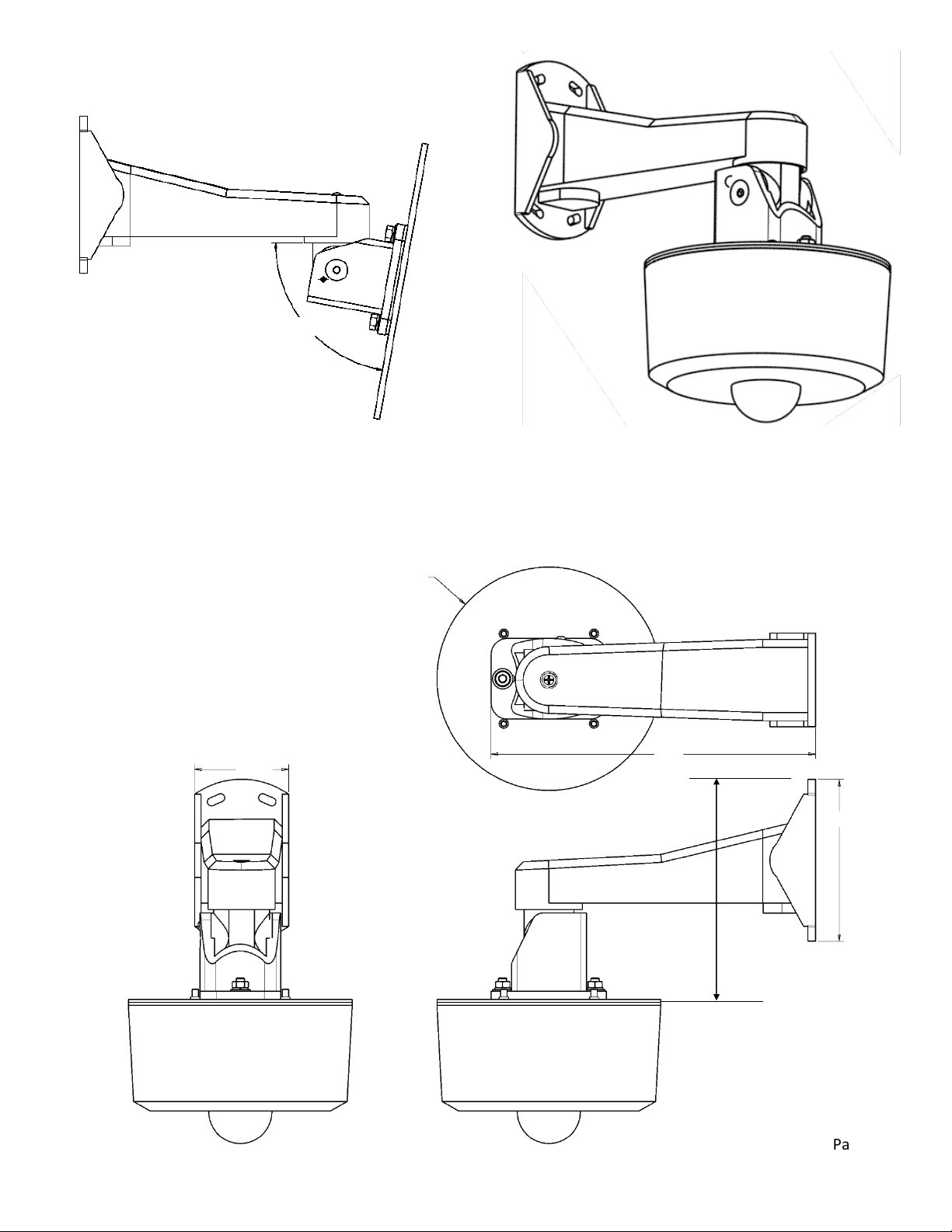
Max
80-deg
Figure 2 –
Assembled &
Side Views
10.0”
254mm
6.9”
176mm
2.9”(74mm)
Figure 3 –
Dimensional
Drawings
5.0”
127mm
7.0”
(178mm)

Page 4of 4
Table of contents
Other Chesapeake & Midlantic Camera Accessories manuals

Chesapeake & Midlantic
Chesapeake & Midlantic BMT-70PM User manual

Chesapeake & Midlantic
Chesapeake & Midlantic BMT-75CM User manual

Chesapeake & Midlantic
Chesapeake & Midlantic BRMT-G5ENV Series User manual

Chesapeake & Midlantic
Chesapeake & Midlantic BMT-52WAT User manual

Chesapeake & Midlantic
Chesapeake & Midlantic BMT-75W Series User manual

Chesapeake & Midlantic
Chesapeake & Midlantic BMT-70A10 User manual

Chesapeake & Midlantic
Chesapeake & Midlantic BMT-H4FA10 User manual

Chesapeake & Midlantic
Chesapeake & Midlantic BMT-M30A10 User manual

Chesapeake & Midlantic
Chesapeake & Midlantic BMT-75PM User manual


