manuals.online logo
Brands
  1. Home
  2. •
  3. Brands
  4. •
  5. Manfrotto
  6. •
  7. Camera Accessories
  8. •
  9. Manfrotto 535 User manual

Manfrotto 535 User manual

INTRODUCCIÓN
Trípodes ligeros de video fabricado en fibra de carbono que combinan una gran
estabilidad con una alta capacidad de carga
y una gran altura máxima con un diseño compacto, ergonómico y fácil de usar.
CARACTERÍSTICAS RESALTABLES
• semiesfera de 75mm (versión 535)
• semiesfera de 75/100mm (versión 536)
• Cada pata se puede configurar independientemente a 3 ángulos (23° - 50° - 70°)
• Pies de goma con pinchós retráctiles
• Conexión para correa de transporte (opcional)
CONFIGURACIÓN
Abra las 3 patas del trípode.
Para ajustar la altura del trípode, cada pata tiene extensiones telescópicas que se
pueden liberar abriendo la pinza “A” sobre el collar de bloqueo “B”. Cuando se
alcanza la altura requerida, cierre el bloqueo de la pinza “A”.
PIES
El trípode tiene pies de goma “Q” con pinchos retráctiles “R” para uso en exteriores.
AJUSTE DEL ÁNGULO DE LA PATA Y
Cada pata se puede configurar a 3 ángulos (X -Y- Z) – ver figura 2
Para cambiar el ángulo de una pata, cierre la pata ligeramente, presione el botón
“C” para seleccionar el nuevo ángulo, luego abra la pata.
El ángulo de cada pata se puede ajustar independientemente de las otras dos
patas.
La última posición permite alcanzar el nivel del suelo.
MONTANDO LA RÓTULA – MODELO 535
El trípode tiene la semiesfera “P” para montar la rótula
MONTANDO LA RÓTULA – MODELO 536
El trípode está diseñado para rótulas con semiesfera de 100mm o 75mm. Para
montar la rótula con semiesfera de 75mm, instale el adaptador “N“ (proporcionado)
al trípode con los tres tornillo “M”.
El adaptador de 75 mm “N” no se incluye si el trípode viene preensamblado con una
rótula de 100mm.
NOTA
También es posible montar una rótula sin semiesfera (base plana con fijación
hembra de 3/8”) en el trípode mediante una semibola que está disponible
opcionalmente:
- 520BALL Ø75 para el trípode 535
- 500BALL Ø100 o 520BALL Ø75 para el trípode 536
TRANSPORTE
El conector “T” para una correa de transporte opcional
AJUSTE DE LA TENSIÓN DEL BLOQUEO DE LAS PATAS
Si las extensiones telescópicas de las patas no quedan bien fijadas, incluso
después de haber cerrado la pinza de bloqueo“A”,
la tensión de bloqueo necesita ser ajustada.
Para hacerlo:
- quite el tapón “K”
- libere la pinza de bloqueo “A”
- atornille la rosca “V” en el sentido de las agujas del reloj, usando la llave especial
“W” que se proporciona en una de las patas del trípode.
Normalmente un tercio de rosca será suficiente para conseguir una tensión de
bloqueo correcta.
1
1
2 3
4
5
6
7
MANTENIMIENTO
Para reemplazar el collar de bloqueo “B” (fig. 1), por favor, use una llave TORX del
número 25 (no proporcionada con el producto).
INTRODUZIONE
Leggero treppiede in fibra di carbonio che combina grande stabilità, elevata portata
e notevole altezza massima, di concezione compatta, ergonomica e di facile uso.
CARATTERISTICHE PRINCIPALI:
• Culla da 75mm (versione 535)
• Culla da 75/100mm (versione 536)
• Apertura indipendente delle gambe su 3 angolazioni (23° - 50° - 70°)
• Piedini in gomma retraibili su puntali
• Attacco per cinghia da trasporto (opzionale)
PREPARAZIONE
Divaricare le 3 gambe.
Per regolare l’altezza del treppiede, ogni gamba dispone di allungamenti telescopici
che si possono liberare ruotando la leva “A” sul manicotto “B”. Ottenuta l’altezza
desiderata, bloccare la leva “A”.
PIEDINI
Il treppiede è dotato di piedini in gomma “Q” con puntai retraibili “R” per l’uso in
esterni.
REGOLAZIONE DELL’ANGOLAZIONE DELLE GAMBE E
Ciascuna gamba prevede 3 angolazioni d’apertura (X -Y- Z) - vedere figura 2.
Per cambiare l’angolazione di una gamba, chiuderla leggermente verso la colonna
centrale e premere il pulsante di bloccaggio “C”. Selezionare la nuova angolazione
e poi rilasciare il pulsante aprendo la gamba verso la posizione desiderata.
Ogni gamba può essere angolata in modo indipendente dalle altre due. La
posizione di massima divaricazione consente le riprese raso terra.
MONTAGGIO DI UNA TESTA – MODELLO 535
Il treppiede è dotato di culla “P” per montare la testa
MONTAGGIO DI UNA TESTA – MODELLO 536
Il treppiede è progettato per teste con semisfera da 100mm oppure 75mm.
Per montare una testa da con semisfera da 75mm, attaccare l’adattatore “N” (in
dotazione) al treppiede con le tre viti “M”.
L'adattatore “N” da 75mm non è incluso se il treppiedi è fornito come kit
preassemblato con testa dotata di semisfera da 100mm.
NOTA
É anche possibile montare teste senza semisfera (base piatta con attacco femmina
da 3/8”) impiegando un adattatore a semisfera, opzionale.
- Semisfera 520BALL Ø75 per treppiede 535
- Semisfera 500BALL Ø100 o semisfera 520BALL Ø75 per treppiede 536
TRASPORTO
Il treppiede è dotato di attacco “T” per cinghia da trasporto opzionale
REGOLAZIONE DELLA TENSIONE DI BLOCCO DELLE GAMBE
Se le sezioni telescopiche tendono a scivolare anche dopo aver serrato le leve “A”,
occorre ripristinare un’adeguata forza di bloccaggio.
A questo scopo:
- rimuovere la protezione “K”
- allentare la leva di bloccaggio “A”
- avvitare la vite “V” in senso orario con la speciale chiave “W” fissata ad una delle
gambe del treppiede.
Normalmente sarà sufficiente la rotazione di un terzo di giro per ripristinare la
corretta tensione di bloccaggio.
1
1
2 3
4
5
6
7
MANUTENZIONE
Per la sostituzione del manicotti “B” (fig. 1), utilizzare una chiave TORX N° 25 (non
fornita con il prodotto).
Cod. 535,51 - 02/12 Copyright © 2008 Manfrotto Bassano Italy
536535
203 cm 3,25 kg 25 kg
80” 7.1 lbs 55.1 lbs
171 cm 2,3 kg 20 kg
67.3” 5 lbs 44.1 lbs
EINFÜHRUNG
Leichtes Video-Stativ aus Kohlenstofffaser, das hohe Stabilität, Belastungsfähigkeit
und große Maximalhöhe mit einem ergonomischen, einfach zu bedienenden und
kompakten Design verbindet.
HAUPTEIGENSCHAFTEN
• 75 mm Schale (Version 535)
• 75/100 mm Schale (Version 536)
• jedes Stativbein kann individuell auf 3 verschiedene Winkel eingestellt werden
(23° - 50° - 70°)
• Gummifüße mit ausziehbaren Spikes
• Gewinde zur Befestigung eines Trageriemens (optional)
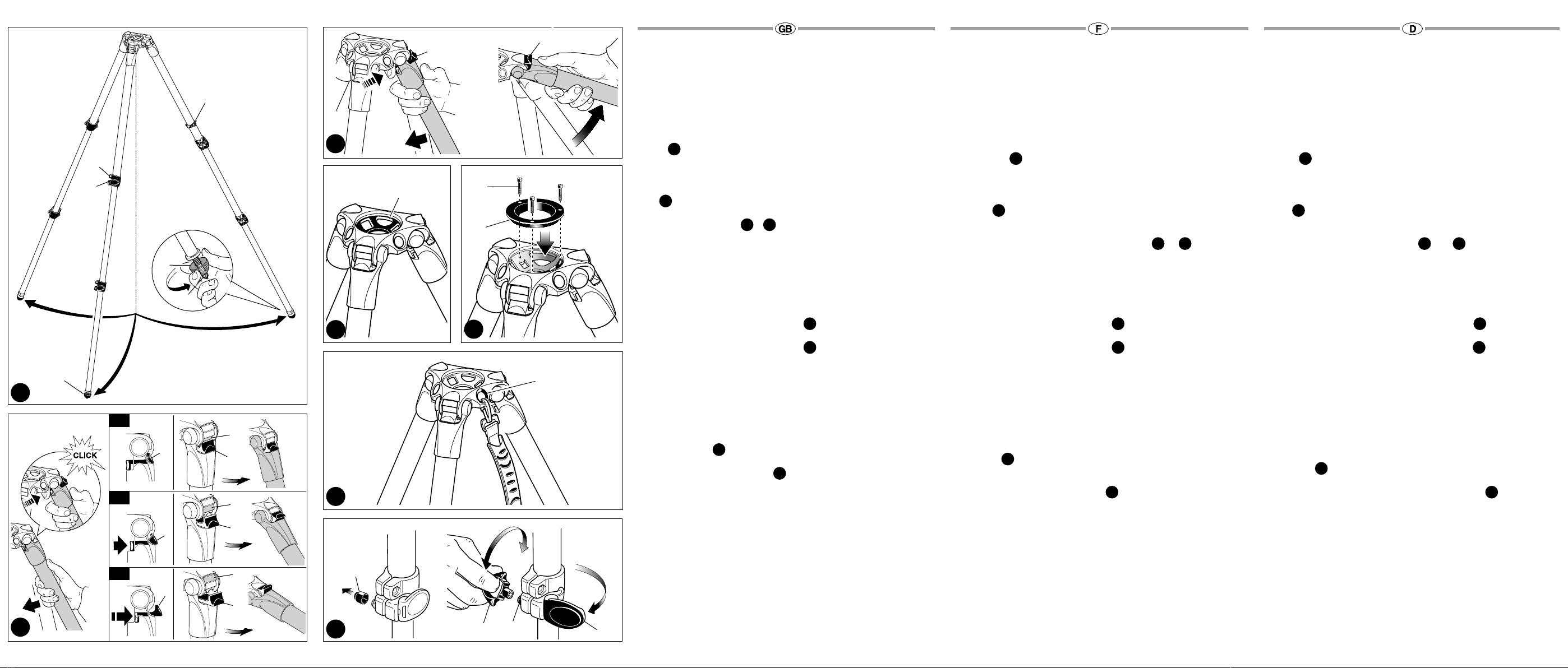
AUFBAU
Ziehen Sie die 3 Stativbeine auseinander.
Um die Höhe des Stativs einzustellen, ist jedes Teleskop-Bein ausziehbar, indem
der Hebel “A” an dem Sicherungsring “B” verstellt wird. Ist die gewünschte Höhe
erreicht, stellen Sie Hebel “A” fest.
FÜSSE
Das Stativ verfügt zur Nutzung im Außenbereich über Gummifüße “Q” mit
ausziehbaren Spikes “R”.
EINSTELLUNG DER WINKEL DER BEINE UND
Jedes Bein kann auf 3 verschiedene Winkel eingestellt werden (X -Y- Z) – siehe Abb. 2
Um einen anderen Winkel einzustellen, ziehen Sie das entsprechende Bein leicht
an, drücken den Knopf “C” zur Wahl des gewünschten Winkels und ziehen das Bein
wieder auseinander.
Der Winkel kann bei jedem Bein individuell eingestellt werden.
Mit dem größten Winkel wird der Boden erreicht.
BEFESTIGUNG EINES KAMERAKOPFES – MODELL 535
Das Stativ verfügt über eine Schale “P” zur Befestigung eines Kamerakopfes.
BEFESTIGUNG EINES KAMERAKOPFES - MODELL 536
Das Stativ ist für Kugelköpfe von 100 mm oder 75 mm konzipiert. Um einen
Kugelkopf von 75 mm anzubringen, befestigen Sie den mitgelieferten Aufsatz “N”
mit den drei Schrauben “M” an dem Stativ.
Der 75mm-Adapter “N” ist nicht im Lieferumfang enthalten, wenn es sich um ein
Stativ in einem vormontierten Bausatz mit einem 100mm-Kugelkopf handelt.
HINWEIS
Es ist ebenfalls möglich, Köpfe, die keine Kugelköpfe sind (Flachboden mit
3/8”-Schrauben), an dem Stativ zu befestigen, indem Halbkugeln verwendet
werden, die optional erhältlich sind.
- 520BALL Kugel Ø75 für Stativ 535
- 500BALL Kugel Ø100 oder 520BALL Kugel Ø75 für Stativ 536
TRANSPORT
Das Stativ verfügt über die Befestigung “T” für einen optionalen Trageriemen
EINSTELLUNG DER VERSCHLUSSSPANNUNG DER BEINE
Wenn die ausziehbaren Teleskop-Beine nicht halten, obwohl der Sicherungshebel
“A” festgestellt wurde, muss die Verschlussspannung eingestellt werden.
Dazu:
- Nehmen Sie den Deckel “K” ab
- Lösen Sie den Sicherungshebel “A”
- Drehen Sie die Schraube “V” an einem der Beine mit dem mitgelieferten
Spezialschlüssel “W” im Uhrzeigersinn.
Meist genügt eine Drittelumdrehung, um die richtige Verschlussspannung zu
erhalten.
1
1
2 3
4
5
6
7
INSTANDHALTUNG
Zum Austausch der Beinklemme “B” nutzen Sie bitte einen TORX Schlüssel Nr. 25
(nicht im Lieferumfang enthalten).
INTRODUCTION
Ces trépieds vidéo légers en fibre de carbone combinent une grande stabilité,
une capacité de charge élevée et une hauteur maximale élevée avec un design
ergonomique, compact et facile à utiliser.
CARACTÉRISTIQUES PRINCIPALES
• Bol de 75mm (modèle 535 uniquement)
• Bol de 75/100mm (modèle 536 uniquement)
• 3 angles d’ouverture possibles des jambes (23° - 50° - 70°), de façon
indépendante
• Embouts en caoutchouc et pointes rétractables
• Anneau pour sangle de transport (en option)
PRÉPARATION
Ouvrez les 3 jambes du trépied.
Pour régler la hauteur du trépied, déployez les sections télescopiques des jambes en
ouvrant les leviers de blocage "A" situés sur les bagues "B". Une fois votre trépied à
la hauteur souhaitée, bloquez les jambes à l’aide des leviers "A".
EMBOUTS
Les trépieds sont équipés d’embouts en caoutchouc "Q" avec pointes rétractables
"R" spécialement conçus pour une utilisation en extérieur.
RÉGLAGE DE L’ANGLE D’OUVERTURE DES JAMBES ET
Chaque jambe peut être ouverte à 3 angles différents (X -Y- Z) (voir figure 2).
Pour modifier l’angle d’ouverture d’une jambe, repliez légèrement la jambe vers le
centre du trépied, appuyez sur le bouton "C" afin de sélectionner l’angle d’ouverture
souhaité, puis ouvrez à nouveau la jambe.
L’angle d’écartement de chaque jambe peut être réglé indépendamment des autres.
L’angle d’écartement le plus grand permet des prises de vues à ras du sol.
MONTAGE D’UNE ROTULE – MODÈLE 535
Le trépied 535 est doté d’un bol "P" permettant la fixation d’une rotule.
MONTAGE D’UNE ROTULE – MODÈLE 536
Le trépied 536 est conçu pour les rotules livrées avec une boule de 100mm ou
75mm. Pour monter une rotule à boule de 75mm, fixez l’adaptateur "N" (fourni) au
trépied à l’aide des trois vis "M".
L'adaptateur 75 mm "N" n'est pas fourni si le trépied est livré sous forme de kit pré-
assemblé avec une rotule 100 mm.
REMARQUE
Il est également possible de fixer des rotules plates (comprenant un filetage de 3/8")
au trépied à l’aide d’une demi-boule (en option).
- 520BALL boule de Ø75 pour le trépied 535
- 500BALL boule de Ø100 ou 520BALL boule de Ø75 pour le trépied 536
TRANSPORT
Les trépieds sont équipés d’un anneau "T" auquel une sangle de transport peut être
attachée.
RÉGLAGE DU BLOCAGE DES SECTIONS
Si après avoir bloqué les jambes avec le levier de blocage "A", les sections
télescopiques glissent légèrement, il faut procéder au réglage du système de
blocage des jambes.
Pour cela:
- retirez le cache "K",
- débloquez le levier "A",
- tournez la vis "V" dans le sens des aiguilles d’une montre à l’aide de la clé spéciale
"W" fournie.
Un tiers de tour doit suffire pour rendre le système de blocage à nouveau efficace.
1
1
2 3
4
5
6
7
ENTRETIEN
Pour remplacer la fonderie de blocage “B”(fig. 1), utilisez une clef TORK N°25
(nonincluse)
INTRODUCTION
Lightweight carbon fiber video tripod that combines great stability, high load
capacity and great max height with an ergonomic and easy-to-use and compact
design.
KEY FEATURES
• 75mm bowl (535 version)
• 75/100mm bowl (536 version)
• Each leg can be independently set at 3 angles (23° - 50° - 70°)
• Rubber feet with retractable spikes
• Attachment thread for carrying strap (optional)
SET UP
Open the 3 tripod legs.
To adjust the height of the tripod, each leg has telescopic extensions that can be
released by rotating lever “A” on the locking collar “B”. When the required height is
achieved, lock lever “A”.
FEET
The tripod has rubber feet “Q” with retractable spikes “R” for external use.
LEG ANGLE ADJUSTMENT &
Each leg can be set at 3 spread angles (X - Y - Z) - see figure 2
To change the angle on a leg, close the leg towards the centre slightly, press button
“C” to select the new leg angle, then open the leg.
The angle of each leg can be adjusted independently of the other two legs.
The last position allows to achieve the floor level.
The angle of each leg can be adjusted independently of the other two legs.
The last position allows to achieve the floor level.
MOUNTING A CAMERA HEAD - 535 MODEL
The tripod has bowl “P” for mounting head
MOUNTING A CAMERA HEAD - 536 MODEL
The tripod is designed for 100mm or 75mm ball heads. To mount 75mm ball heads,
attach the adapter “N” (provided) to the tripod with the three screws “M”.
The 75mm adapter “N” is not included if the tripod is supplied as a pre-assembled
kit with a 100mm ball head.
NOTE
It is also possible to mount non ball (flat base with 3/8” female fitting) heads on the
tripods by using a half ball, which is available as option.
- 520BALL Ø75 ball for 535 tripod
- 500BALL Ø100 ball or 520BALL Ø75 ball for 536 tripod
TRANSPORTATION
The tripod has an attachment “T” for optional carrying strap
LEG LOCK TENSION ADJUSTMENT
If the telescopic leg extensions slip even after having tightened the locking lever “A”,
the locking tension will need to be adjusted.
In order to do this:
- remove cap “K”
- release lock lever “A”
- turn the screw “V” clockwise using the special key “W” provided on one of the
tripod legs.
Normally a third of a turn will be sufficient to achieve the correct locking tension.
1
1
2 3
4
5
6
7
MAINTAINANCE
In order to replace locking collar “B” (fig. 1), please use a TORX key number 25 (not
supplied with product).
1
3
2XA
V
1
1
1
2
3
2
3
K
C
C
C
C
C
C
X
Y
Z
W
A
Q
CC
N
M
P
Q
R
T
B
45
6
7
Z
X
Y

This manual suits for next models

1

Other Manfrotto Camera Accessories manuals

Manfrotto 528X User manual

Manfrotto

Manfrotto 528X User manual

Manfrotto 724B User manual

Manfrotto

Manfrotto 724B User manual

Manfrotto MVG220 User manual

Manfrotto

Manfrotto MVG220 User manual

Manfrotto Joby Pixi Plus User manual

Manfrotto

Manfrotto Joby Pixi Plus User manual

Manfrotto 303SPH User manual

Manfrotto

Manfrotto 303SPH User manual

Manfrotto 330B User manual

Manfrotto

Manfrotto 330B User manual

Manfrotto 131D User manual

Manfrotto

Manfrotto 131D User manual

Manfrotto 350MV User manual

Manfrotto

Manfrotto 350MV User manual

Manfrotto MVH612AH User manual

Manfrotto

Manfrotto MVH612AH User manual

Manfrotto 132 User manual

Manfrotto

Manfrotto 132 User manual

Manfrotto 482LCD User manual

Manfrotto

Manfrotto 482LCD User manual

Manfrotto 678 User manual

Manfrotto

Manfrotto 678 User manual

Manfrotto MH293D3-Q2 User manual

Manfrotto

Manfrotto MH293D3-Q2 User manual

Manfrotto 357 User manual

Manfrotto

Manfrotto 357 User manual

Manfrotto HiLite LL LB8803 User manual

Manfrotto

Manfrotto HiLite LL LB8803 User manual

Manfrotto 560B User manual

Manfrotto

Manfrotto 560B User manual

Manfrotto MT190GOA4 User manual

Manfrotto

Manfrotto MT190GOA4 User manual

Manfrotto MKC3-H01 User manual

Manfrotto

Manfrotto MKC3-H01 User manual

Manfrotto 405 User manual

Manfrotto

Manfrotto 405 User manual

Manfrotto 685B Quick start guide

Manfrotto

Manfrotto 685B Quick start guide

Manfrotto ART. 190CXPRO3 User manual

Manfrotto

Manfrotto ART. 190CXPRO3 User manual

Manfrotto MVM500A User manual

Manfrotto

Manfrotto MVM500A User manual

Manfrotto 7301YB User manual

Manfrotto

Manfrotto 7301YB User manual

Manfrotto MTWISTGRIPH User manual

Manfrotto

Manfrotto MTWISTGRIPH User manual

Popular Camera Accessories manuals by other brands

Ikelite 200DL manual

Ikelite

Ikelite 200DL manual

Robus Vantage 3 Series user manual

Robus

Robus Vantage 3 Series user manual

Gerbing B7V-2500 user manual

Gerbing

Gerbing B7V-2500 user manual

Intermec CK30 instructions

Intermec

Intermec CK30 instructions

Okina USA SIR-754AILP-IO Operation & installation manual

Okina USA

Okina USA SIR-754AILP-IO Operation & installation manual

Autel Robotics Dragonfish Lite quick start guide

Autel Robotics

Autel Robotics Dragonfish Lite quick start guide

DesQ 327 operation instruction

DesQ

DesQ 327 operation instruction

KATA AB-301 quick start guide

KATA

KATA AB-301 quick start guide

Eco 30 P Series Installation manual and comissioning

Eco

Eco 30 P Series Installation manual and comissioning

Blueshape MVQUICK operating instructions

Blueshape

Blueshape MVQUICK operating instructions

Philips SJB2142 Specifications

Philips

Philips SJB2142 Specifications

ABB 83327-500 manual

ABB

ABB 83327-500 manual

Ryobi GDM610 Owner's/operator's manual

Ryobi

Ryobi GDM610 Owner's/operator's manual

Nauticam NA-R7 user manual

Nauticam

Nauticam NA-R7 user manual

Avalon AFB2 Installation and operation manual

Avalon

Avalon AFB2 Installation and operation manual

First National Battery RAYLITE M-SOLAR Installation and maintenance instructions

First National Battery

First National Battery RAYLITE M-SOLAR Installation and maintenance instructions

Viewpro Q10F user manual

Viewpro

Viewpro Q10F user manual

Fotima FTF-160 user manual

Fotima

Fotima FTF-160 user manual

manuals.online logo
manuals.online logoBrands
  • About & Mission
  • Contact us
  • Privacy Policy
  • Terms and Conditions

Copyright 2025 Manuals.Online. All Rights Reserved.