manuals.online logo
Brands
  1. Home
  2. •
  3. Brands
  4. •
  5. Nauticam
  6. •
  7. Camera Accessories
  8. •
  9. Nauticam 26350 User manual

Nauticam 26350 User manual

Current as of 2020-03-16
26350 Flash Trigger for Nikon
(Compatible w/ NA-
5/ 500/ 850/Z7)
Instruction Manual
F
OREWOR
Thank you for your purchase of a NAUTICAM product.
At NAUTICAM, we pride ourselves in the ability to recogni e the
requirements of professional as well as amateur underwater photographers
and fulfill them through the innovative designs of our products. We strive to
achieve a high level of user-friendliness by allowing stress-free installation
and easy operation of all important functions of the camera.
Please read this manual carefully before using the product, this will maximi e
its performance as well as its lifetime.
W
ARRANTY
All NAUTICAM Products are warranted against any material and
manufacturing defects for two years from the date of purchase for consumer
use.
This warranty only applies to products purchased from authori ed
NAUTICAM dealers and does not extend beyond the original retail purchaser.
To return your product for service, please contact your regional authori ed
service center(s). Please note that this warranty only applies when the
product is purchased in the territory where the service center is located.
NAUTICAM does not hold responsibility for damage, of any nature, to any
equipment used with and/or placed within our products.
NAUTICAM accepts no liability for any loss of captured images or the inability
to capture images even if it is due to the malfunctioning of our products.
Unauthori ed modifications and/or repairs of our products will automatically
invalidate the warranty.
Product photos may differ from actual products.
P
RECAUTIONS
•Use only batteries approved for use in this product, do not mix old and
new batteries.
•Check the battery terminals before installing into the product.
•Remove batteries for storage, do not store the product in an environment
of high humidity.
•Do not leave the product in direct sunlight for prolonged periods.
•Keep out of reach of children, failure to do so could result in injury.
•Defective products should be shipped to our distributors for service,
unauthori ed disassembling and/or modifications could result in mal-
function.
I
ENTIFICATION OF
P
ARTS
I
NSTALLATION
Remove the original LED flash trigger from the housing by unscrewing the
two screws as indicated above.
Install the TTL converter and simultaneously insert both LEDs into the optical
bulkheads.
ATTENTION: Using any thin long tool (for e ample a small allen key) to push
both LEDs as deep inside the optical bulkheads as possible. The LED must be
close to the transparent optical element inside the bulkhead to get normal
quality of TTL work, otherwise you will get a wrong e posure of underwater
shots.
Insert CR2032 batteries into battery holders. Before installation check that
“plus” terminal of each battery is in Up position.
Carefully check fiber optical cables. Recommended to use only original
NAUTICAM fiber optical cables. In case of using bad quality or damaged
cables you will get a wrong exposure of underwater shots.
C
ABLE
C
ONNECTIONS
TTL-Converter maintains synchroni ation for underwater strobes by
Fiber Optical cable connection and by electric cable connection as well.
Maximum 2 pcs Nauticam Fiber Optic cables can be connected (via
housing optical bulkheads).
IMPORTANT! Nauticam Dual fiber optic cables cannot support reliable
TTL operation at optical bulkheads in this system, because of their
connector construction. Please use only single fiber optic cables.
Maximum 2 pcs Electric cables can be connected (via housing electric
bulkheads).
Dual electric cables (“Sea&Sea”, “Ikelite”) are supported by system at
each electric bulkhead as well.
TTL
-
converter switch
Battery compartment
LED
Socket for electric
bulkhead
Status Indicator
Remove
Socket for electric
bulkhead
NA
-
5
NA
-
500
Remove
Trigger connector
TTL on/off
connector
connector
TTL Data
connector
connector
Ready Clock
connector
Ground connector
Current as of 2020-03-16
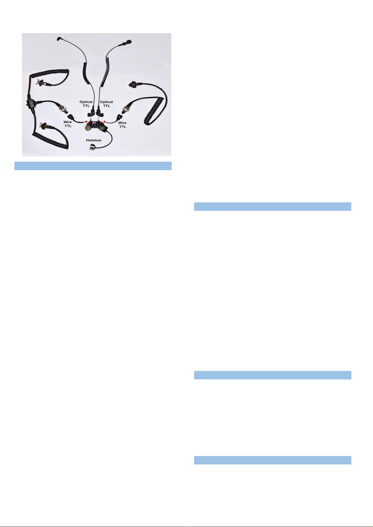
Scheme of available cable connections:
S
HOOTING IN
TTL
M
O E
•Set and check camera settings before underwater shooting:
-Set appropriate camera’s Exposure Meter Type (“Matrix”, “Central-
weighted, “Point”) according your shooting tasks. Right type of
exposure metering is the key setting for accurate TTL work. In case
of wrong setting, the shot may be overlighted, or underlighted.
-For TTL operation user can set desired sync speed by camera menu,
excluding sync speeds marked as “Auto FP”. According the
construction underwater strobes cannot work in FP synchroni ation,
that is why “Auto FP” camera command is free for them, and it is
assigned in TTL Converter firmware for switching system to
“Controlled Manual Mode”. Photographer should use it to switch
TTL / M underwater.
- Set “exposure compensation” and “flash exposure compensation”
to “0ev”, as initial settings.
- Set appropriate ISO. TTL-Converter can work in ISO range
50….25600. Recommended to use ISO 50….400 for best resolution
and TTL accuracy underwater. For Macro shooting recommended
ISO 50-100.
Be careful choosing extremely high ISO or “Auto-ISO” mode, it may
cause overlighting by underwater strobes.
- Set camera aperture and shutter speed according real underwater
conditions and shooting task.
- Set recommended apertures F8-F16 for wide angle photo, and F16-
F22 for Macro photo, as initial settings.
- Use other settings recommended by your camera User’s Manual.
•For normal TTL accuracy the minimum distance from strobe to an
underwater subject must be no closer than 0.35 m.
•Set underwater strobe dial switch to desired TTL mode. Please refer to
strobe User’s Manual to choose appropriate mode. Usually it marked
“S-TTL” (“TTL”, “DS-TTL”) on the strobe’s body.
•Set (+/-Ev) dial switch on the strobe body to “0ev” position, as initial
setting for Optical TTL usage.
•For Z-240 electric wire TTL usage set (+/-Ev) dial switch to position “TTL”
(another words “9 o’clock” position)
•Set TTL-Converter rotary switch according your strobes type:
o0 – Simple Manual Mode (no TTL, pre-flashes are disabled)
o1 – Inon Z-240 / Z330
o2 – Sea&Sea YS-D1
o3 - Sea&Sea YS-D2
o4 - Sea&Sea YS-250
o5 - IkeliteDS-161/160
o6 - Inon D200/S2000
o7 - F1-SF150-SF160
o8 - reserved
o9 - reserved
•Slide Hot Shoe connector into the camera Hot Shoe socket.
•Camera recogni es Nikon compatible TTL device on its HotShoe and
confirms it by appropriate symbol “Flash”on the service screen.
•Dive and make TTL underwater photo, checking image quality and
histogram via camera LCD.
•Dependently of concrete underwater subject type, strobes condition,
ambient light underwater and etc., photographer should use +/- TTL
correction (“Flash Exposure Compensation”) to reach balanced TTL
lighting.
•Photographer can adjust +/-TTL correction by 2 ways:
- Use optical +/- TTL correction (+/-Ev) dial switch on the
underwater strobe body (available for Fiber-optical connection
only).
- Use camera’s “flash exposure compensation” function for +/- TTL
correction (available for both Fiber-optical TTL and Electric Wire
TTL connections). Available range for Nikon cameras “Flash
exposure compensation”: -3ev…0...+1ev. User can adjust it by
steps 0.3ev or 0.5ev (set by camera menu), viewing +/-Ev value on
the camera screen.
•TTL-Converter maintains normal accuracy TTL lighting control only for
underwater conditions. Land tests may give little bit different results.
•Continuous shooting in CL/CH camera modes are available for all
modes of TTL Converter. But, underwater strobe usually recycles a
significant time, so the shots in series will have different lighting. To
reach a constant lighting for few shots in series, user should shoot in
Manual mode at minimum strobe powers.
•TTL-Converter activates automatically (switch ON) when user pushes
camera’s Shutter Release Button for focusing or shooting. Device goes
to standby mode (switch OFF) also automatically few seconds later,
according the camera command, or after disconnection of camera’s
HotShoe.
•IMPORTANT! In some shooting conditions TTL may be not effective or
out of working range. This case please use Manual modes.
S
HOOTING IN
C
ONTROLLE
M
ANUAL
M
O E
•Switching to Controlled Manual mode during the dive (underwater) is a
useful feature. It gives possibility to set strobe power manually by the
camera controls. User need not to set power manually on underwater
strobe body, he can keep hands on the housing.
•Underwater strobes must be set in “S-TTL” (“DS-TTL II”) mode. Strobe’s
dial (+/-Ev) corrector set to “0” position.
•Switch TTL-Converter to Controlled Manual Mode using the camera
menu:
Bracketing/flash >> Flash sync speed >> 1/200 (Auto FP).
Camera setting for any sync speed marked as “Auto FP”, points TTL-
Converter to Controlled Manual Mode without pre-flashes. Then
underwater strobe light power can be adjusted by camera controls,
using “flash exposure compensation” function.
•Available adjustment range for underwater strobe: from Minimum
strobe’s power (displays as “-3ev” on camera screen) to Maximum
strobe’s power (displays as “+1ev” on camera screen). Possible to set
step 0.3ev or 0.5ev, by menu.
•TTL-Converter does not make pre-flashes in this mode.
•Pay attention, that “Auto FP” function also makes available to set very
fast shutter speeds on the camera. To avoid mistakes for lighting using
underwater strobes, set shutter speeds not faster than speed of
synchronization for your camera. Most Nikon cameras with mechanical
shutter have maximum sync speed 1/200 or 1/250 (without Auto FP).
Some old Nikon cameras have electronic shutter and maximum
synchroni ation speed up to 1/500 (without Auto FP).
S
HOOTING IN
S
IMPLE
M
ANUAL
M
O E
Switch system to “M” mode by setting TTL-Converter onboard rotary
switch to “0” position. This operation can be done only before
submerging, when the housing is open. The constant Manual mode will
be set in the system.
TTL protocol is totally disabled. In this mode TTL-Converter makes fixed
pulse at each shutter release of the camera.
Such mode is recommended for creative shooting with long fiber optic
cables (up to 40 m length).
In this Manual mode all Pre-flashes are disabled in system. User should
set “M mode without Pre-flashes” by the dial switch on the strobe body,
and adjust strobe light intensity by the second dial switch on the strobe
body.
S
HOOTING IN
M
ANUAL
M
O ES OF
U
N ERWATER
S
TROBE
•Photographer can easy set Manual mode using the main dial switch on
the strobe body, independently of TTL-Converter current mode. This is
simple classic way to switch for shooting in Manual mode.
•Set appropriate type of M mode on the strobe body:
If TTL-Converter is in TTL mode, then set “Manual mode with pre-
flashes” by the switches on the strobe body.
Current as of 2020-03-16
If TTL-Converter is in “Controlled Manual Mode” or “Simple
Manual Mode”, then set “Manual mode without pre-flashes” by
the switches on the strobe body.
•Adjust strobe light power by the second dial switch on the strobe body.
S
HOOTING WITH
F
LASH
O
FF
•Photographer can assign “Fn“ button to option “flash off” (by camera
menu).
•Pushing the “Fn” button, user can shoot with flash off.
S
TATUS
I
N ICATOR
The status indicator will display the battery status as well as modes selected.
It will flash GREEN/BLUE/RED when shutter release is triggered.
GREEN – In TTL mode, battery OK.
BLUE – In Manual mode, battery OK.
RE – Battery low, replace battery.
S
TORAGE
After shooting please switch off the camera.
Slide off TTL-Converter’s connector from the camera’s Hot Shoe socket.
This way you defend the TTL-Converter from any accidents. Also, you
save TTL-Converter’s battery, because its current consumption is
minimum then.
For a long time storage remove batteries from TTL-Converter.
O
PTIONAL
A
CCESSORIES
26704 M14 Nikonos 5-pin Bulkhead with Micro Connector for Nikon TTL
Converter (Compatible with NA-D5/D500)
26705 M14 Ikelite Style Bulkhead with Micro Connector for Nikon TTL
Converter (Compatible with NA-D5/D500)
26216 Universal Optical Fiber Cable
S
PECIFICATIONS
Compatible Cameras:
All Nikon DSLR
Compatible Housings:
Nauticam NA
-
D5 / NA
-
D500
/ NA
-
D850
Compatible TTL Strobes:
INON: Z
-
240 type4
, Z330,
D200/S2000
Sea&Sea: YS-D1, YS-D2, YS-250
Ikelite: DS-161, DS-160
F1-SF150-SF160
TTL Outputs:
2 Optical, 2 Electric wire
Camera ISO range:
50 ~ 25600
Continuous Shooting:
Compatible
Rear Curtain Sync:
Compatible
Switching TTL/M modes
underwater: Yes, by camera menu
TTL
Flash Exposure
compensation: Yes, by camera controls
Maximum
Fiber
optic
cable length for “TTL”
operation:
3meters
On/Off switch:
Automatic
Battery Type:
CR 2032 x2pcs
Battery Capacity:
5
-
7
years or 75000 flashes
Dimensions:
85mm x 45mm x 13mm
Weight:
Approx. 25g (without batteries)

Other Nauticam Camera Accessories manuals

Nauticam 16335 User manual

Nauticam

Nauticam 16335 User manual

Nauticam NA-EM5 User manual

Nauticam

Nauticam NA-EM5 User manual

Nauticam 36060 User manual

Nauticam

Nauticam 36060 User manual

Nauticam N85 User manual

Nauticam

Nauticam N85 User manual

Nauticam NA-S1H User manual

Nauticam

Nauticam NA-S1H User manual

Nauticam NA-G7XII User manual

Nauticam

Nauticam NA-G7XII User manual

Nauticam NA-RX100 User manual

Nauticam

Nauticam NA-RX100 User manual

Nauticam NA-SHINOBI-H User manual

Nauticam

Nauticam NA-SHINOBI-H User manual

Nauticam 26301 User manual

Nauticam

Nauticam 26301 User manual

Nauticam 18809 User manual

Nauticam

Nauticam 18809 User manual

Nauticam NA-DP4 User manual

Nauticam

Nauticam NA-DP4 User manual

Nauticam 16347 User manual

Nauticam

Nauticam 16347 User manual

Nauticam SFE2470GM-Z User manual

Nauticam

Nauticam SFE2470GM-Z User manual

Nauticam SFE1224-F User manual

Nauticam

Nauticam SFE1224-F User manual

Nauticam NA-OM-1 User manual

Nauticam

Nauticam NA-OM-1 User manual

Nauticam N105VR-F User manual

Nauticam

Nauticam N105VR-F User manual

Nauticam 16120 User manual

Nauticam

Nauticam 16120 User manual

Nauticam 83222 User manual

Nauticam

Nauticam 83222 User manual

Nauticam 26306 User manual

Nauticam

Nauticam 26306 User manual

Nauticam 16301 RC815-Z CANON EF 8-15MM F/4L FISHEYE USM ZOOM... User manual

Nauticam

Nauticam 16301 RC815-Z CANON EF 8-15MM F/4L FISHEYE USM ZOOM... User manual

Nauticam NA-GX85 User manual

Nauticam

Nauticam NA-GX85 User manual

Nauticam C1635III-Z User manual

Nauticam

Nauticam C1635III-Z User manual

Nauticam 19598 User manual

Nauticam

Nauticam 19598 User manual

Nauticam NA-LX100II User manual

Nauticam

Nauticam NA-LX100II User manual

Popular Camera Accessories manuals by other brands

CamRanger CamRanger user manual

CamRanger

CamRanger CamRanger user manual

Custom Brackets HDV CAGE KIT Instructions for use

Custom Brackets

Custom Brackets HDV CAGE KIT Instructions for use

Aegis ABL052010P user manual

Aegis

Aegis ABL052010P user manual

Saft SRA Series Installation and operating instructions

Saft

Saft SRA Series Installation and operating instructions

Kodak TIB5200 technical information

Kodak

Kodak TIB5200 technical information

Videotec HEG instruction manual

Videotec

Videotec HEG instruction manual

Ikelite 6171.11 manual

Ikelite

Ikelite 6171.11 manual

Pentax Auto Bellows Slide Copier K user manual

Pentax

Pentax Auto Bellows Slide Copier K user manual

Nikon UT-1 user manual

Nikon

Nikon UT-1 user manual

dji RONIN 4D quick start guide

dji

dji RONIN 4D quick start guide

SLIK ABLE 300DX user manual

SLIK

SLIK ABLE 300DX user manual

Rebelcell 36V70 user manual

Rebelcell

Rebelcell 36V70 user manual

Trojan GC2 48V quick start guide

Trojan

Trojan GC2 48V quick start guide

Calumet 7100 Series CK7114 operating instructions

Calumet

Calumet 7100 Series CK7114 operating instructions

Ropox 4Single Series User manual and installation instructions

Ropox

Ropox 4Single Series User manual and installation instructions

Cambo Wide DS Digital Series Main operating instructions

Cambo

Cambo Wide DS Digital Series Main operating instructions

Samsung SHG-120 Specification sheet

Samsung

Samsung SHG-120 Specification sheet

Ryobi BPL-1820 Owner's operating manual

Ryobi

Ryobi BPL-1820 Owner's operating manual

manuals.online logo
manuals.online logoBrands
  • About & Mission
  • Contact us
  • Privacy Policy
  • Terms and Conditions

Copyright 2025 Manuals.Online. All Rights Reserved.