ESPER TriggerBox User manual


Table of Contents
Overview 2
Accessories 4
Safety Warning 4
Connecting the TriggerBox to Cameras 5
Trigger Modes 7
Connecting the TriggerBox in 'All Trigger' (GREEN MODE) 7
Connecting the TriggerBox in 'Smart Trigger' (BLUE MODE) 8
Connecting the TriggerBox in 'Hybrid Trigger' (GREEN & BLUE MODES) 10
TriggerBox Controller Software 11
Download TriggerBox Software 13
Installing the software 14
Interval Mode 15
Delay Mode 17
Serial Instruction Set 18
Set-up procedure 18
Camera trigger notes 18
TriggerBox command modes 19
Complete commands list 20
Using Flashes 23
Camera combination 27
Troubleshooting 30
Steps to take before contacting support 30
Hardware issues 32
Software issues 32
Firmware 35
Technical Specifications 36
Compatibility 36
Two-Year Warranty 37
1

Overview
Thank you for buying an ESPER TriggerBox. The TriggerBox allows multiple camera shutters to be
released from a computer or a single hardware release cable. Please refer to the instructions below to
properly understand the functionality of hardware in your multi-camera setup.
Front
1. Input: 3.5mm 3 Pole Jack Opto-Isolated
for connecting the remote shutter
release
2. Link: 3.5mm 3 Pole Jack Opto-Isolated
for connecting multiple units
3. Mode Switch: Green (All Trigger) / Blue
(Smart Trigger)
4. USB-C: Control, Program and Power the
TriggerBox via a computer
2
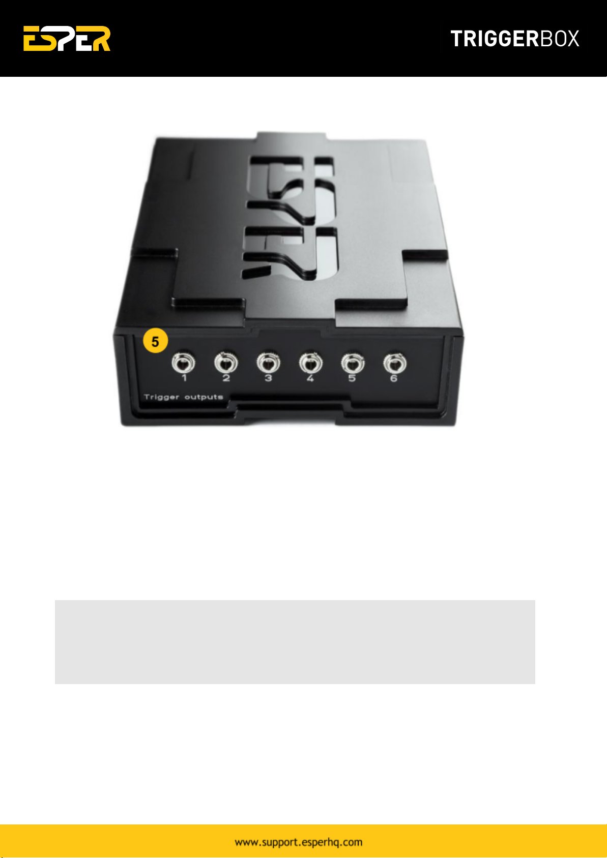
Back
5. Outputs: 6 x Opto-isolated 3.5mm 3 Pole Jacks for connecting cameras and flashes
What is included:
●ESPER TriggerBox
●1m USB-A to USB-C cable
●Multi-region universal power supply
If you purchased the ESPER TriggerBox as a bundle it may include additional cabling.
Note: Please check all the contents of your order upon receipt of goods. If you receive a delivery
and an item is missing, please notify us within 48 hours of your order collection. Issues raised after
this period are subject to possible rejection, resulting in the denial of a replacement of the missing
item. You can still return your item/s within 30 days of the date of receipt of your order and receive
a refund.
3

Accessories
Multiple TriggerBox units can be used to trigger an unlimited number of cameras and flashes.
Additional triggers can be purchased at
https://www.esperhq.com/product/multiple-camera-trigger-triggerbox/.
Camera connecting cables are available for many different cameras makes and models. Additional
camera cables can be purchased at https://www.esperhq.com/products/?show=all.
TriggerBox is designed to stack neatly together with the PowerBox units. Multi-camera power solution
can be purchased at https://www.esperhq.com/product/multi-camera-power-supply-powerbox/.
Safety Warning
To prevent injury to yourself or to others make sure to read the following safety precautions before
using the equipment. Please read and follow these instructions:
●Do not disassemble or modify the product.
●Do not expose the product to high temperatures, severe cold or high humidity.
●Keep out of the reach of children.
●Turn off immediately in the event of a malfunction.
●Do not operate the unit in the presence of flammable gas or vapours.
●Do not attempt to disassemble or perform any unauthorised modification.
●Turn off the power of the camera before inserting or removing the trigger cables.
●Make sure the item is intact and that there are no missing parts.
●Turn off the camera and flash, before attaching or removing the ESPER TriggerBox.
4

Connecting the TriggerBox to
Cameras
Follow these 3 steps and you'll get your Esper TriggerBox up and running in no time. By the end, you'll
have your cameras connected and ready to start using.
Step 1. Connecting your cameras to the TriggerBox
Each camera is connected to a single output socket of the TriggerBox (fig.1 a) via a 3.5mm adaptor
cable.
Figure 1. ESPER TriggerBox - Trigger outputs.
Step 2. Linking multiple TriggerBoxes together
Multiple TriggerBoxes can be connected together to allow for the triggering of more than 6 cameras to
create larger multi-camera setups. Multiple TriggerBoxes are linked by connecting a 3.5mm stereo
cable to the link socket (fig.2 a) of the first TriggerBox and then to the input (fig.2 b) of the next unit
and repeating down the line.
Figure 2. ESPER TriggerBox front panel.
5

Step 3. Switching between TriggerBox modes
The TriggerBox is switchable between two modes of operation. Switch between the two modes by
pressing the 'Mode' LED button (see fig. 3) on the front of the unit.
Figure 3. Mode LED switch
●LED is Green (fig.3 a) : All Trigger mode – all 6 outputs and the link socket fire at once when
a shutter release is connected to the input socket.
●LED is Blue (fig.3 b) : Smart Trigger mode – all 6 outputs and the link socket can be fired from
a computer or a shutter release plugged into the TriggerBox input. All the outputs can be
individually turned on and off, delayed and programmed in sequences, via the USB connection.
6

Trigger Modes
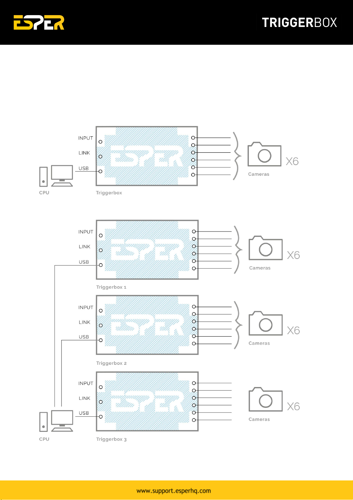
Connecting the TriggerBox in 'All Trigger' (GREEN
MODE)
1. Connecting a Single TriggerBox - in All Trigger (GREEN MODE)
2. Connecting Multiple TriggerBoxes - in All Trigger (GREEN MODE)
7
Connecting the TriggerBox in 'Smart Trigger' (BLUE
MODE)
1. Connecting a Single TriggerBox - in Smart Trigger (BLUE MODE)
2. Connecting Multiple TriggerBoxes via CPU - in Smart Trigger (BLUE MODE)
8

3. Connecting Multiple TriggerBoxes - in Pre-Programmed Smart Trigger (BLUE MODE)
Tip: When in 'Smart Trigger' (BLUE) Mode, it is possible to programme the TriggerBox with a
computer and then store the setting 'in memory' for triggering at a later time by a computer or
remote shutter release.
9
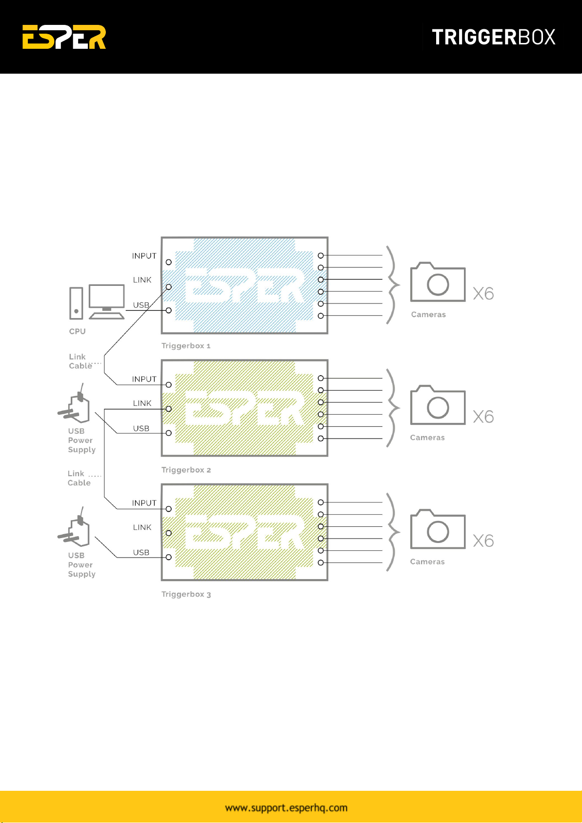
Connecting the TriggerBox in 'Hybrid Trigger' (GREEN &
BLUE MODES)
1. Connect Multiple TriggerBoxes as a Hybrid Trigger (GREEN & BLUE MODES)
Switch the first TriggerBox in the chain to 'Smart Trigger' Mode (BLUE) and connect to a Computer.
Connect flashes and / or camera models and link together with your remaining TriggerBoxes and switch
them to 'All Trigger' Mode (GREEN).
10

TriggerBox Controller Software
The TriggerBox Controller software allows firing the TriggerBox outputs from a computer as well as
accessing the advanced features of the box.
●Outputs - 1-6 and the link socket can be selectively turned on and off.
●Delay - values can be assigned to outputs 1-6 allowing tighter synchronization between
different camera models and with flash/strobe lighting.
●Sequencing - sequence up to 8 stages with different settings for a more creative shot.
●Bulb mode timer – assigns a fixed length of time to the trigger button press.
●Intervalometer – fires all 6 outputs at pre-determined intervals or time periods with bulb
ramping.
11

Top menu:
Function
Description
Connect
Connects all TriggerBoxes switched to 'Smart Trigger' (Blue mode).
Reset
Boxes
Resets all TriggerBoxes settings to default.
Select All
boxes
Selects all the connected TriggerBoxes. Any changes made on the screen will be
made to all the selected boxes.
Copy
screen to
Selected
The current screen settings will be copied to the selected TriggerBoxes.
Send to
box
memory
Saves the current settings to the selected boxes memory, when in blue mode the
TriggerBox will start up with these settings. Use this to store settings for a
permanent fixed installation where there is no need to change settings.
Box Lights
On
Switches the mode light on or off for all the selected TriggerBoxes. Useful should a
mode light be visible in the shot.
Identify
Selected
Trigger
Boxes
Flashes the mode light of the selected TriggerBoxes to aid identification and
naming.
Outputs 1-6:
Function
Description
Join
Links the toggling of Shutter and Focus operations across all outputs.
Shutter
Turns the shutter release off and on for each output.
Focus
Toggles the autofocus line off and on for each output.
Shutter -
All
Toggles outputs 1-6 shutters on/off.
Focus - All
Toggles output 1-6 Focus on/off.
12
Bottom:
Function
Description
Pre-Focus
Toggles the camera to focus before the closing of the shutter - please note if this
is running on a battery this will increase the power consumption considerably.
Half Press
Simulates holding down the camera shutter release button to the halfway point.
Big Red
Button
Fires the Shutters.
Download TriggerBox Software
To download the TriggerBox Controller software 1.6 click here:
https://s3-us-west-1.amazonaws.com/espercontrollersoftware/Triggerbox/TriggerBoxController-1.6.zip
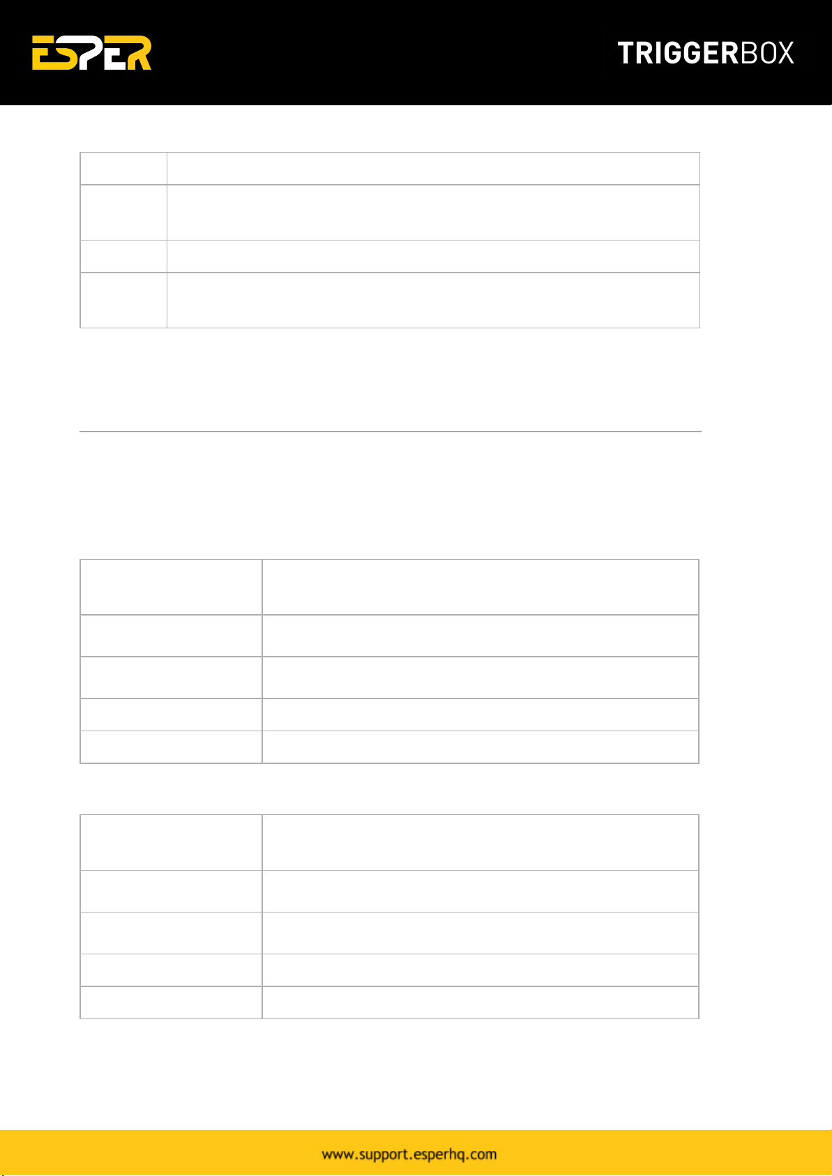
The following are the system requirement for installing ESPER TriggerBox Controller Software and
operating and setting the cameras from your PC.
Windows System Requirements
Operating System
Windows XP SP2, Windows Vista, Windows 7, Windows 8, Windows
10. USB with 2.0 port must be standard equipment.
CPU
Processor with 2GHz or faster.
RAM
A minimum of 512 MB of RAM.
Monitor
Monitor Resolution 1024 X 768 or higher.
Free Storage
250 MB or more.
Macintosh System Requirements
Operating System
Mac OS X 10.3.9 or later preinstalled. USB with 2.0 port must be
standard equipment.
CPU
PowerPC G4 1GHz or faster.
RAM
A minimum of 512 MB of RAM.
Monitor
Monitor Resolution 1024 X 768 or higher.
Free Storage
250 MB or more.
13
Installing the software
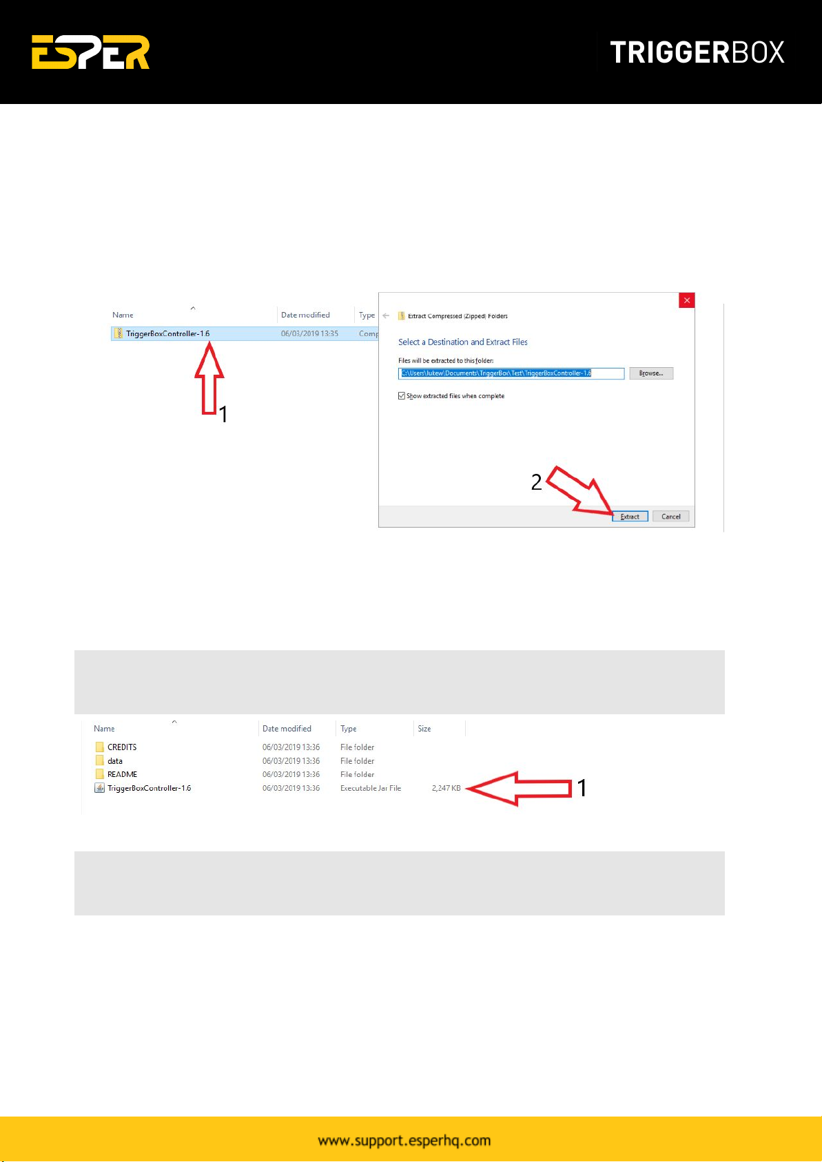
1. Download the latest version of the ESPER TriggerBoxController software here. The software will
download within a zip file (fig. 4.1). Once it has finished downloading right click and extract all to
'TriggerBoxController-1.6' folder (fig. 4.2).
Figure 4. TriggerBoxController software zip file
2. Once extracted, you will see 3 folders and the TriggerBoxController-1.6.jar file. Keep all files &
folders in this folder. Double click the TriggerBoxController-1.6.jar file to open the software (fig. 5.1).
Note: When you first run the software it will check you have an up to date version of Java and
prompt a download if you don’t.
Figure 5. TriggerBoxController Software Extracted
Tip: If the application won’t open then check that your version of Java is up to date here
http://www.java.com/en/download/installed.jsp
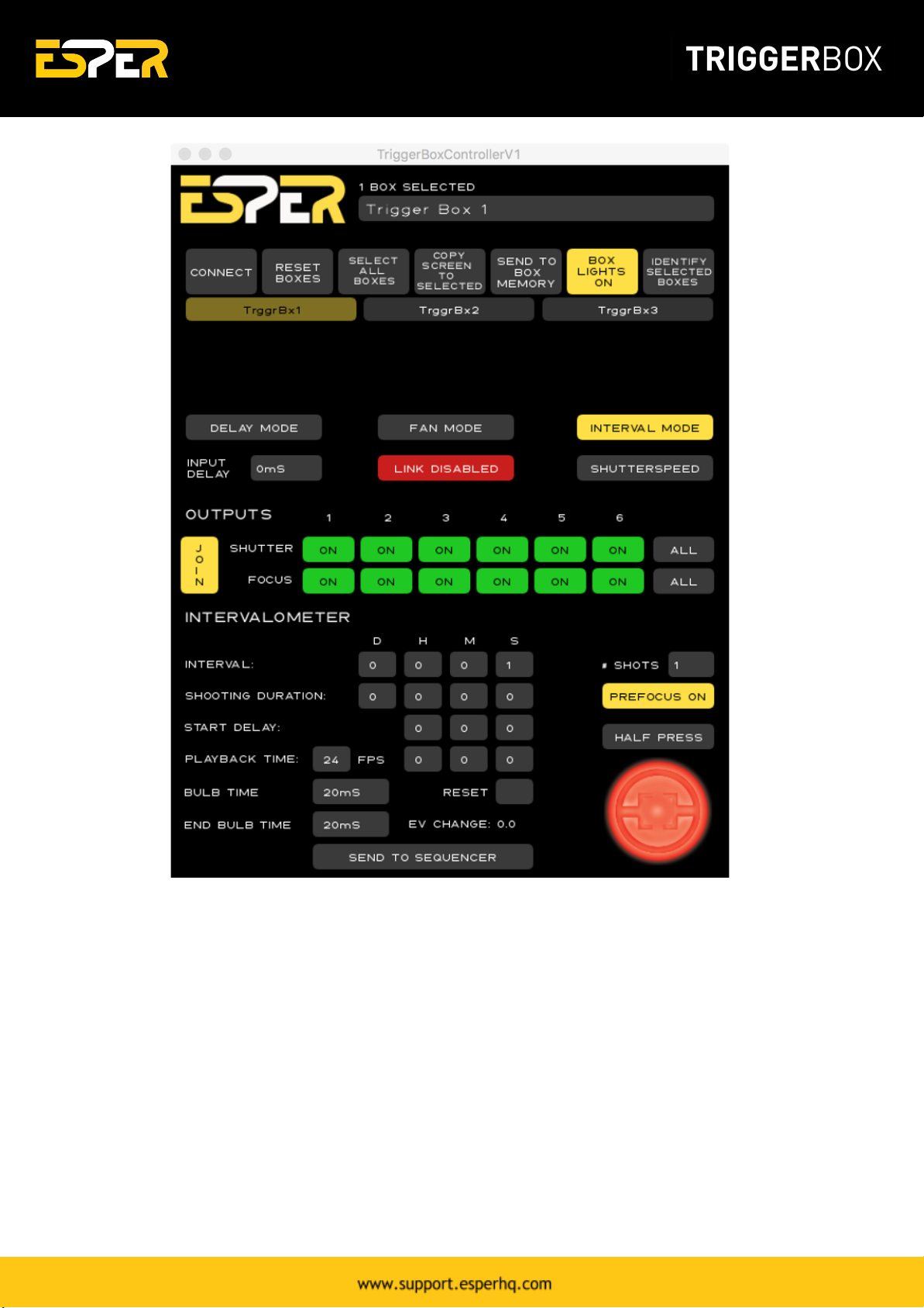
3. Once open you need to press 'Connect' on the ESPER software and the available boxes will appear
under the 'Connect' button. You can then select one or multiple boxes and alter each boxes settings
and fire using the big red button located in the bottom right corner.
14

Figure 6. TriggerBoxController software - connecting a TriggerBox
Interval Mode
Interval Mode allows the TriggerBox to be used as a multi-channel intervalometer all 6 outputs fire at
once on all the connected TriggerBoxes. To allow for the creation of multi angle time lapse sequences,
useful in both research and creative applications.
The intervalometer can set the interval between shots, the total duration of shooting, the total
number of shots, the total playback time of the clip, delaying the start of shooting, exposure ramping
by varying the bulb time over the duration of shooting.
The intervalometer can also be used to step between sequence stages in delay mode allowing for the
construction of complex sequences of images from different angles over a period of time.
15
●Interval – the interval between shots.
●Shooting duration – the total duration of shots.
●Start Delay – Delay the start of intervalometer shooting by up to 23 hrs 59 mins and 59 secs.
●Playback Time – set the frame rate (fps) and total playback time of the sequence.
●Bulb Time – set the length of the shutter button press- note this setting is carried across to
both delay mode and fan mode.
●End Bulb Time – set the length of the bulb time.
●Reset – zeros intervalometer settings.
●Send to sequencer – the fire signal from the intervalometer is sent to the sequencer to allow
the automatic stepping through of sequencing settings.
●# shots – total number of shots.
16

Delay Mode
Sequencer
The TriggerBoxController can run an 8 step sequencer – the sequencer moves to the next step by either
pressing the red button or connecting an external trigger to the input connection.
Add Sequence Stage
Add another sequence stage. Once added, you are able to add in delays different from the previous
sequence.
Remove Sequence Stage
Removes the last sequence added. All settings will also be removed once the sequence is deleted.
Repeat Stage
Repeats stage – Please Note stage repeats are only available when controlling the TriggerBox from the
TriggerBox Controller software – if the sequence settings are saved to the box memory and the
TriggerBox is triggered using a wire remote the TriggerBox will cycle to the next sequence step when it
receives a signal at its input.
17

Serial Instruction Set
Everything you need to know about controlling ESPER TriggerBox from your own software. Learn about
set-up procedure, camera trigger notes and command modes.
Set-up procedure
1. Connect TriggerBox to the computer.
2. Ensure box switch is set to blue mode.
3. Ensure OS has identified TriggerBox as USB Serial Port (Windows)/ FT232R USB UART (Mac).
4. Drivers should install automatically. If not, the latest COM port drivers can be found at:
www.ftdichip.com/Drivers/VCP.htm?
Any TriggerBox running firmware 1.2 will communicate at 115200baud, no stop bits, no parity bit.
Instructions to the TriggerBox must be printed using standard ASCII encoding. Any instructions sent to
the box must end with a \n (newline) character. The TriggerBox acts as a basic COM port, which must
be opened and closed after every session. The specifics of opening and closing COM ports are
platform/software dependant, refer to your software/library user guide.
The first character of an instruction specifies either an action to be performed immediately, e.g. "S" to
fire shutters, or defines a programmable parameter, e.g. "s000111" to enable only the last three
shutter outputs. TriggerBox settings can be saved to the internal memory (EEPROM) through the "O"
command. Upon power-up the box will recall saved settings, negating the need to program again.
Any timing value sent to the TriggerBox is in milliseconds, and has a valid range of 0 to 30,000
milliseconds.
Camera trigger notes
Many cameras require that their focus input is asserted before they will react to a shutter signal. This
depends on the make, model and camera settings. If possible, it is advised to set the camera to full
manual exposure mode and disable autofocus to achieve the most consistent timings.
Different cameras respond at different rates to the combination of asserting the focus line followed by
the shutter line. Therefore, it is sometimes required to insert a delay between the focus command and
shutter command.
Tip: Many common camera model performance values can be found at
http://www.imaging-resource.com/cameras/reviews/. While these values may not be definitive for
every use case, they are a good starting point.
18

While the focus line is asserted, most cameras will not respond to communication via USB or physical
button presses on the camera. Therefore, it is critical that the focus line is de-asserted using "F0"
before attempting to download images or change settings. Some camera models require that the focus
line is de-activated between each shot when using mirror-lockup or bulb mode.
TriggerBox command modes
The TriggerBox has two command modes, Simple Mode and Sequence Mode.
Simple Mode
Simple mode allows the user to enable individual focus and shutter outputs and upon receipt of an "S"
command will release the enabled outputs.
Example Simple Mode six camera command string:
<set-up>
m0 (set box to Simple Mode)
s111111 (enable all shutter outputs)
f111111 (enable all focus outputs)
<each shot>
F1 (focus camera)
<wait camera response time value> (allow camera to respond to half button press)
S (release shutter)
F0 (release focus)
Sequence Mode
Sequence mode allows the user to specify up to eight stages. Each stage allows every output's shutter
and focus line to be enabled as well as an assignable output delay. The default sequencer setting only
has one sequence stage. The first stage is labelled zero. Up to seven subsequent stages can be added
using the command "P".
A shutter release command will cause the sequencer to advance to the next stage.
A select stage command "jx" allows the sequencer to be started from stage x.
Example Sequence Mode command string:
<set-up>
m2 (set box to Sequencer Mode)
19
Table of contents


