CHESTER U.K. B-Super 3-in-1 User manual

ModelBSuper3in1
InstructionManual
ChesterUKLtd
ClwydClose,HawardenIndustrialPk
Hawarden,NrChester
Flintshire.CH53PZ
Tel:01244531631
Email:sales@chesteruk.net
www.chesteruk.net

IMPORTANT
SAFETYFIRST
ALLMACHINESAREDANGEROUS
1.Usethecorrecttoolforthejobathandnevermakeamachinedoajobitwasnotdesignedfor.
2.Neverforcethe toolinthemachineitwilldothequickerandsaferatthecorrectrate.
3.Alwaysuseclampsorvicestosecurework– yourhandisnotstrongenough!
4.Whenchangingtoolsorworkpiecesalwaysdisconnectthemachinefirst.
5.Servicethemachineregularly;acorrectlyoperatingmachineisasafermachine.
6.Alwaysreplacebeltcoversbeforestartingthemachine.
7.Understandthemachinefullybeforeoperationandalwaysreadthemanual.
8.Gettoknowthemachineslimitationsandapplications.
9.Ensurethatthemachineissecurelyboltedtothebenchandthatthebenchissecurelyboltedtothe
ground.
TAKEGREATCAREWHENOPERATINGTHISMACHINETOPROTECTYOURBODY
1.Alwayswearsafetyglasses–everydayglassesarenotsuitable.
2.Dustcanbecausedwhenmachiningcertainmaterials,alwayswearamask.
3.Makesureyouarenotwearinganylooseclothingsuchasties,rings,braceletsthatmaygetcaughtin
themovingpartsofthemachine.
4.Keepaproperfootingandbalancewhilstoperatingthemachine.
5.Neverleavecleaningrags,etconornearthemachine.
ChesterUKModelB
1.

SAFETYFIRST
ELECTRICS
1.Allelectricaltoolsmustbeearthed.
2.Neveruseelectricaltoolsindamporwetenvironment.
3.Makesurethemachineisintheoffpositionbeforeswitchingonatthemains.
4.Alwaysimmobilisethemachinebeforeservicingorsettingupworkinthemachine.
5.Greatcareshouldbetakenwhenusingcoolantfluidwithmachinetools.
6.Ensurethemachineiscorrectlyconnectedandafuseoftheproperratingisused.
CHILDREN
1.Keepchildrenawayfrommachines,ifnecessaryfitsafetylockstothemachineandmainsswitches.
2.Neverusemachinerywhilsttalkingtovisitors,alwaysconcentrateonthejobinhand!
REMEMBERALLMACHINESARE
DANGEROUSIFNOTUSED
CORRECTLY!
ChesterUKModelB
2.
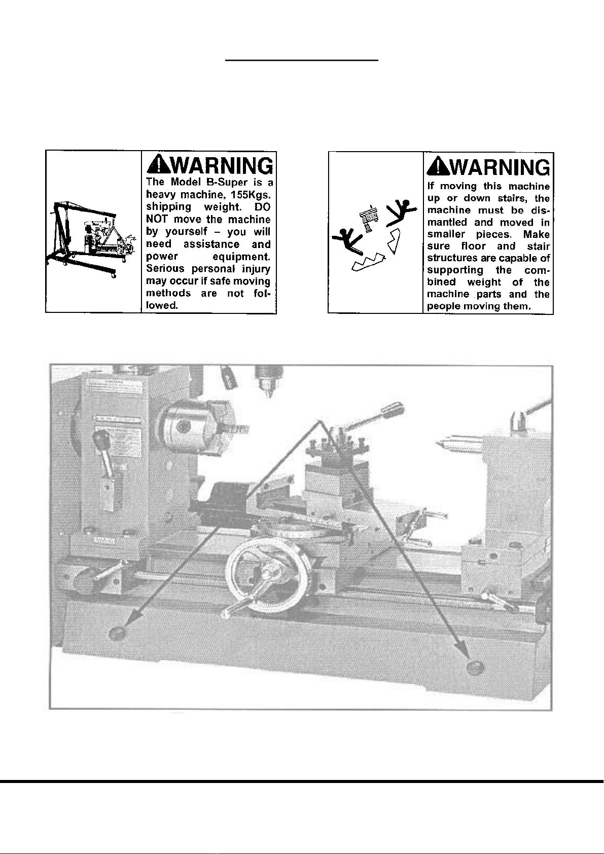
LIFTINGMACHINE
TheModelBrequirestheuseofliftingequipmentsuchasaforklift,enginehoistorboomcrane.Donot
liftmachinebyhand.Seethewarningbelow.Usedinconjunctionwithliftingstrapsandfollowingsafe
liftingproceduresasdetailedbythemanufacturesofthese liftingdevices,thelathe/ millcanbesafely
liftedoffofthepalletandplacedonasturdyworkbench.
Donotliftthemachinefromanyotherpointsthanthosepicturedin Figure2.
ChesterUKModelB
3
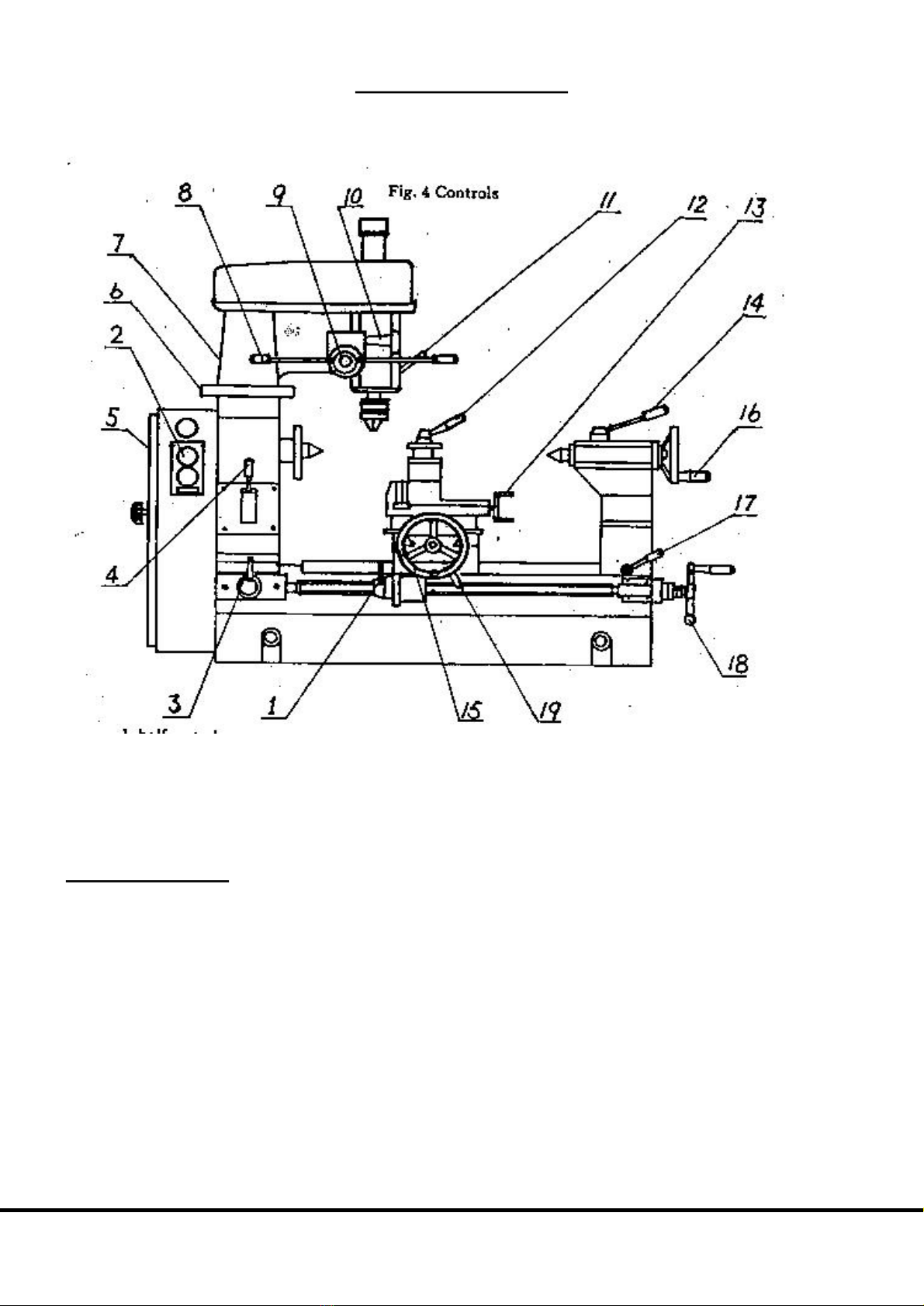
IDENTIFICATION
Figure4.ThefollowingisalistofcontrolsandcomponentsontheModelB.Pleasetaketimetobecome
familiarwitheach item and its location.These terms will beused throughoutthemanual andknowing
them will aid in comprehension. Most of these terms will be shown in italics (italics) throughout the
manual.
MACHINETERMS
1.Halfnutslever 10.Microfeedhandle
2.Powerswitch 11.Drillingmillingclamplever
3.Screwclutchlever 12.Toolpostlocklever
4.Speedchangelever 13.Machinevicehandle
5.Clutchhandle 14.Tailstockbarrelclamplever
6.Thedrillingmillingunit 15.Transversemotionhandle
updownhandle 16.Tailstockbarrelhandwheel
7.Theunitlocklever 17.Tailstocklocklever
8.Drillingoperatinglever 18.Longitudinalmotionhandle
9.Clutchhandle 19.Carriagelocklever
ChesterUKModelB
4
ASSEMBLY&SETUP
Thissectionwillcoverthebasicsinassemblyandsetup.Werecommendyoucompleteassemblyinthe
orderinwhichitispresentedtoachievethebestresults.
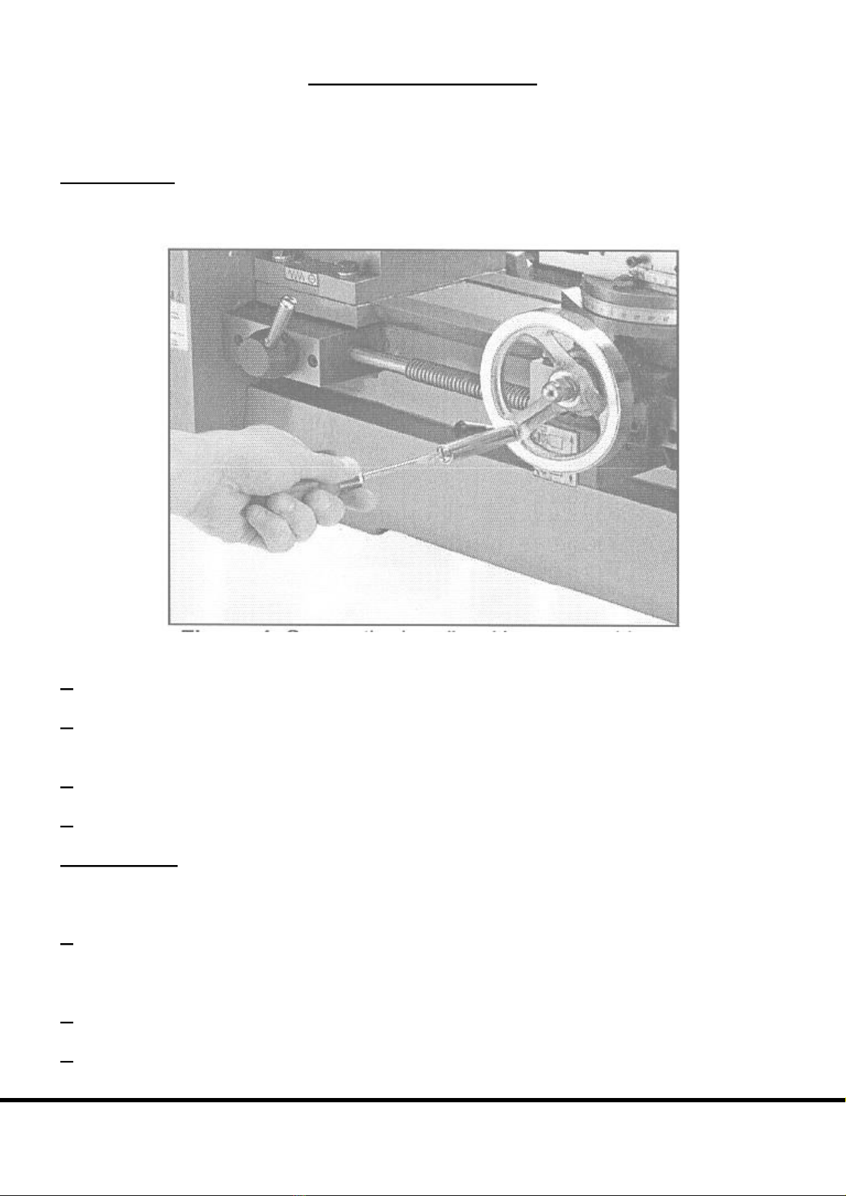
HANDWHEEL
Thehandwheelfortheapronmustbeinstalled.
Figure5.Securethehandlewithascrewdriver.
1.RemovetheacornnutandwasherfromthecrossfeedLeadScrew.
2. Slide the handwheel onto the cross feed Lead Screw. Note the key way that is in the bore of the
handwheelandorientitsoitalignswiththekeyonthecrossfeedLeadScrew.
3.Securethehandwheelwiththeacornnutandwasher.
4.SecurethehandleforthehandwheelwithascrewdriverasinFigure5.
HANDCRANK
Thehandcrankforthelongitudinalmanualfeedmustbeinstalled.
1. Theendofthe LeadScrew has asmall holethat iscrossdrilled near itsend.The handcrank has a
similarholedrilled intotheedgeofthecentreball.Orienttheseholestoeachotherandslidethehand
crankontotheendoftheshaft.
2.Rotatethehandcrankontheshaftuntiltheholesalign.
3.Placethe4mmrollpinintotheholeasin Figure6anddriveitinwithahammer.
ChesterUKModelB
5
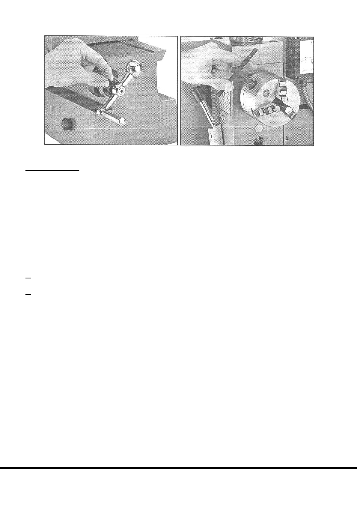
Figure6.PlacerollpininholeandtapwithhammerFigure7.Rotatechuckkeytoopen/closejaws
LATHECHUCK
TheModelBLathe/Millcomesequippedwitha3jaw(alreadyinstalled).
The3jawchuckisascrolltypechuck,meaningthatallthreejawsmoveinunisonwhenadjustmentsare
made. Most 4jaw chucks, on the other hand, feature jaws which are adjusted independently. A 4jaw
chuckcanbeusedtoholdsquareorrectangularstock.
The3 jaws,ona3JawChuck,openandcloseusingthechuckkeyprovided.Pleasereferto Figure7.
Rotatingthekeyclockwiseclosesthejaws.
Tousethismountingplate:
1.Fastentheplatetothe4jawchuckusingthescrewsprovidedwiththechuck.
2.Fastentheplattothespindleusingthe3screwsthatwereremovedfromthe3jawchuck.
DONOTmountchucksmeasuringlargerthan5”indiameteronthisspindle.
Some4jawchucksmaynotreadilymounttothebackplateprovided.Itmaybenecessarytodrillnew
mounting holes and/or resurface and shoulder the plate so the chuck may be mounted accurately and
safely. Should you have questions regarding this, please consult your local technical school, trained
expertorothertraderesources.
ChesterUKModelB
6

LATHECHUCKREMOVAL
Toremoveachuck:
1.Placeapieceofplywoodacrossthelathebedandpositionitjustunderthechuck.Theboardshouldbe
atleast8”wideand10”long.
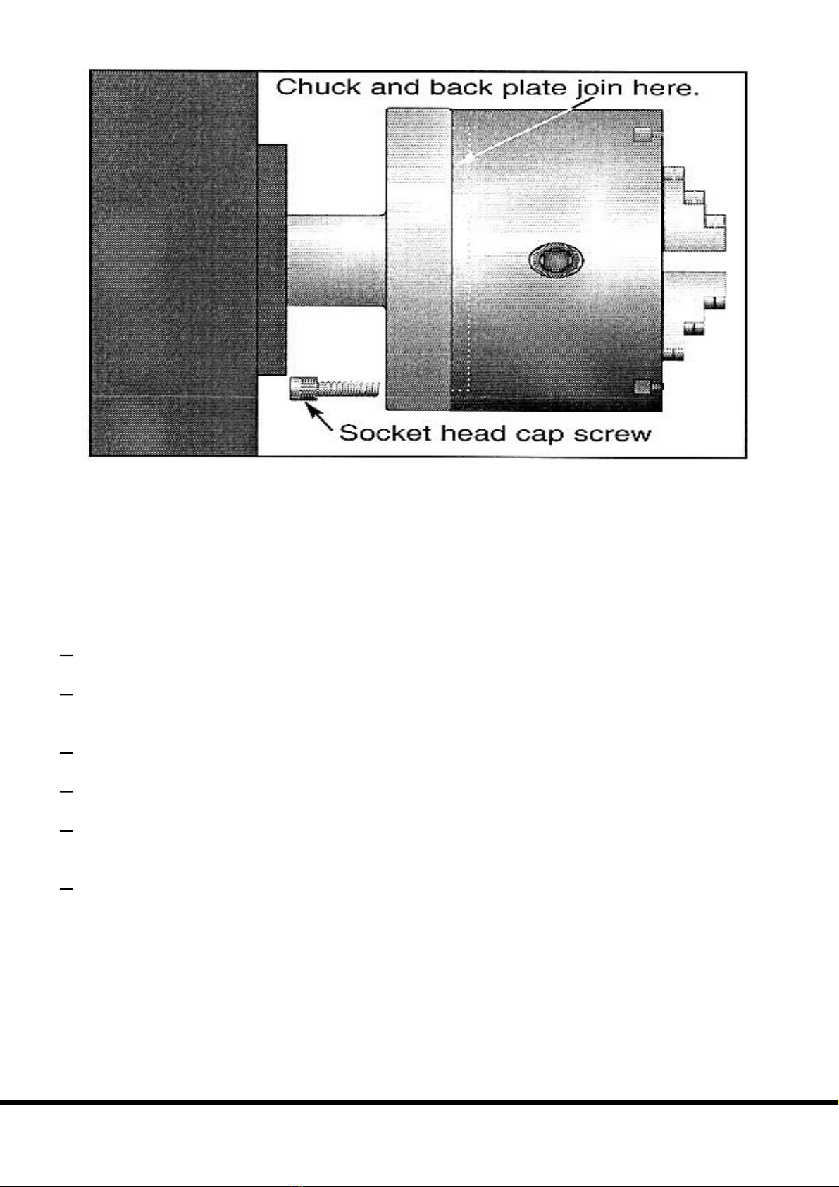
2.Locatethe3socketheadcapscrewsonthebackofthebackplateandremove2ofthem.Pleasesee
Figure8.
3.Removethelastscrew,whilstmakingsuretosupportthechuckwithonehand.Thechuckmaycome
offasthelastscrewisremoved,soitisimportantthatyouarereadytosupportitsweight.
4.Removethechuck.
ChesterUKModelB
7
Ifthechuckisstilltightonthespindle:
Taptheedgeofthechuckwitharubberorwoodenmalletwhilesupportingthebottomofthechuckwith
yourfreehand.Ifthechuckdoesnotimmediatelycomeoff,rotatethespindleapproximately60ºandtap
again.
Toinstallachuck:
1.Placeapieceofplywoodacrossthelathebedandpositionitjustunderthespindle.
2.Placeasocketheadscrewintooneoftheholesinthebackplate.Liftthechuckuptothespindleand
alignthethreadedholeinthebackofthechuckwiththescrew.
3.Whilesupportingtheweightofthechuck,turnthescrew3turns.Donottightenatthistime.
4.Rotate thespindleandrepeatstep3 onthelasttwoscrews.
5.Returntothefirstscrewandtightenitalittlemore.Tightentheotherscrewsaswellbutonlyenough
thatthegapbetweenthechuckandthebackplateremainseven.
6.Finally,tightenallthreescrewsuntilthegapbetweenthechuckandthebackplateisclosed.
ChesterUKModelB
8

DEADCENTRE
The dead centre is used to support stock that is too long to be supported by the chuck alone. Stock
protrudingmorethan2½timesitsdiameter,shouldbesupportedbyadeadorrollingcentre.
Figure9.Deadcentreinstalledintailstock.
Thetailstockbarrelandcentrehavea MorseTaper#3.Beforeassemblingthese, insurethatthemating
surfaces are“white glove” clean. Cleanthe matingsothey are freeofdirt and oil. Theseparts will last
longerandremainaccuratewhenproperlycleanedbeforeassembly.Morsetaperswillnotinterlockwhen
dirtoroilarepresentonthemountingsurfaces.
Insert the end of the centre into the tailstock bore until it seats. The force of the centre contacting a
mountedworkpiecewillfullyseatthetaperwhenthehandwheelistightened.
When using a centre, the tailstock barrel should protrude about ½” and not more than 1¼” out of the
tailstockbody.SeeFigure9.
Toremovethelivecentre,backthetailstockbarrelallthewayintothecastingbyturningthehandwheel,
on the end of the tailstock, counterclockwise. The live centre will pop out. Besure to hold it before it
comesoutlestitdroponthelathebed.
ChesterUKModelB
9

TOOLPOST
TheModelB comes supplied with a4 wayturret tool post. It isdesignedto accept upto 14tool bits.
OtherdevicesandholdersmaybeinstalledintothetoolpostandarrangedasinFigure10.Whenmore
thanonetoolissecuredintothetoolpost,changingfromonetooltoanotherisquicklydonebyloosening
thelock lever(5)androtatingtheposttothedesiredtool. Aspringloadedcatchisinstalledbelowthe
toolpost.Thisallows motioninonlythecounterclockwisedirection.Thecatchcausesthetoolpostto
stop at the same rotational point for each tool placement. This feature can be used for some types of
machiningsetups.Pleasenotethatthesecurenessofthetoolpostisnotdependentuponthecatch.Thus,
thetoolpostcanbepositionedatanyrotationallocationandproperlysecuredwiththelocklever.
If using tool bits that require shimming, be sure to use steel shims as opposed to aluminium or brass
shims.Softshimsmaygive,allowingthetoolbittobecomeloose!
Figure10.Fourtoolsmountedintothetoolpost:
1.BoringBar 2.LeftCuttingToolBit
3.ThreadingToolBit 4.RightTurningToolBit
5.LockLever
Whensecuringatoolbitintothetoolpost,alwaysremembertheserules:
· Securethetoolbitwithatleast2boltsonthetoolpost
· Make sure the top of the tool bit is at the lathe spindle centre line or just below. The tailstock
centrecanbeusedasin Figure11.
· Neverextendthetoolbitmorethan2½timesitsthicknessfromedgeofthetoolrest,i.e.a3/8”
toolbitshouldonlyextend15/16”pastthebottomofthetoolrest.Lessisbest!
· Alwaysusesharptoolbits.
Figure11.Usingacentretochecktoolbitheight.
ChesterUKModelB
10
DRILLCHUCK
TheModelBcomessuppliedwithadrillchuckandarborthatcanbeusedinthetailstockonthelatheor
inthespindleforthepress.Thearboranddrillchuckareassembledandinstalledintothespindleforthe
drillpressspindleatthefactory.
DRILLCHUCKREMOVAL
Toremovethedrillchuckfromthedrillpress:
1.Unplugthemachine.
2.Returnthespindletothehighestposition.
3.Removethesmallplasticcapontopofthebeltguard.
4.Graspthedrillchuckwithonehandandunscrewthedrawbar3 turnswiththeother.
5.Securethequillwiththequilllock.
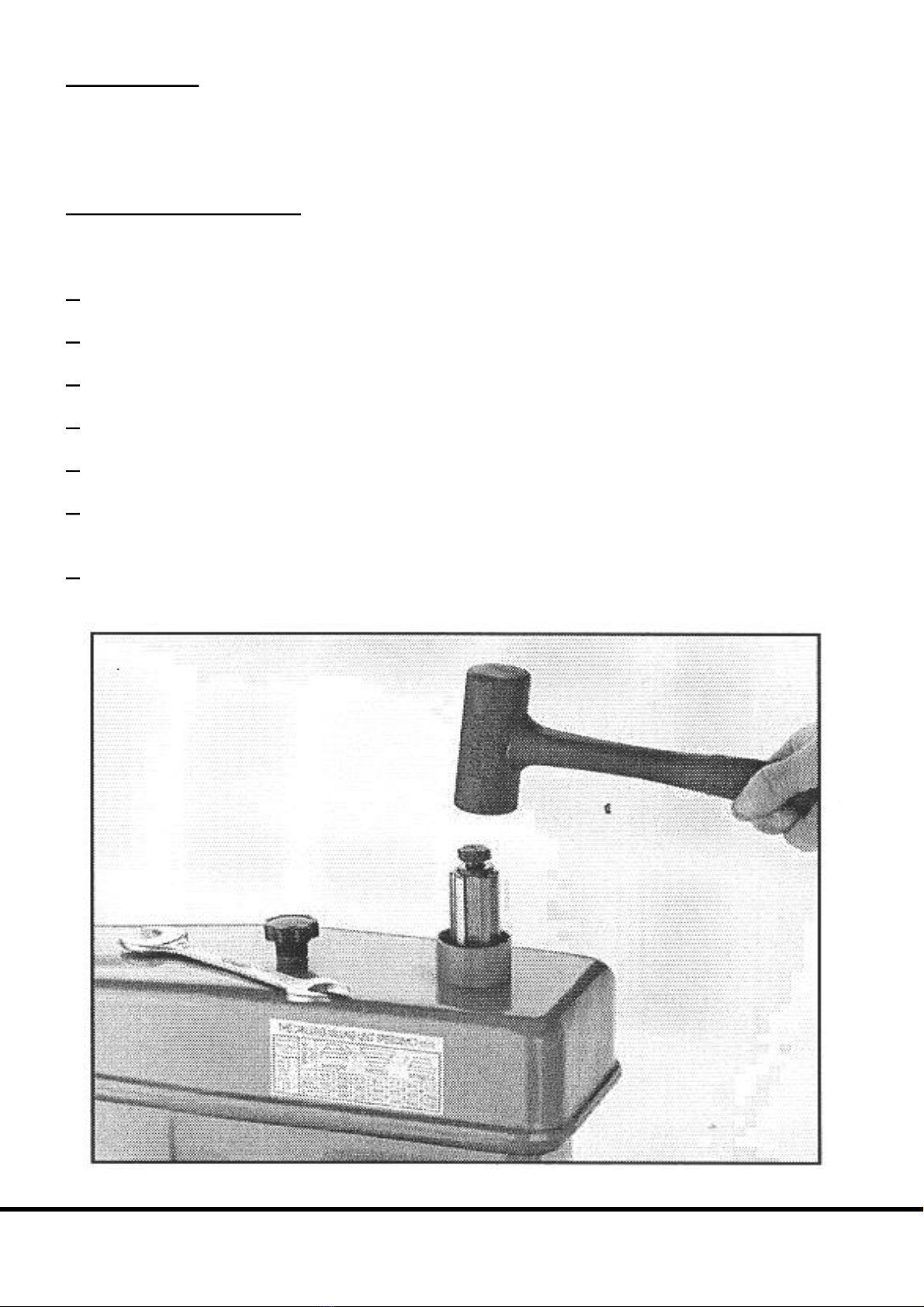
6.TapontheendofthedrawbarwithasoftfacedmalletasinFigure12.Donotuseasteelhammer!
Damagetothedrawbar,suchaschipping,mayoccur.
7.Oncethearborhasbecomeloose,holdthedrillchuckwithonehandwhileunthreadingtheremainder
ofthedrawbolt.
Figure12.Removingdrillchuck
ChesterUKModelB
11
DRILLPRESSMOUNTING
Tomountthedrillchuckintothedrillpress:
1.Removethesmallplasticcapontopof thebeltguardandslidethedrawbaroutofthespindlethrough
thetop.
2.Insertthearborhalfwayintothedrillpressspindle,thenquicklyslideitinplace.
3.Replacethedrawbarandthreaditintothearbor.Donotovertighten!Thedrawbaronlyneedstobe
lightlytightened.Tighteninganyfurtherwillmakeitdifficulttoremovethearbor!
LATHEMOUNTING
Priortomountingthedrillchuckintothetailstockwipetheinsideofthetailstockbarrelandarbordown
withacleanclothandinspectthemfornicksorscratches.Anyirregularitiesonthesurfaceofthearboror
inside thetailstock barrel will hinder thelocking capabilityofthetaper andshould bedressed smooth
withafinefile.
Tomountthedrillchuckintothetailstockofthelathe,slidethearborintothetailstockbarrelaboutone
halfoftheway.Withaquickmotion,finishslidingthechucktherestoftheway.Thisshouldseatitwell
intothetailstockbarrel.
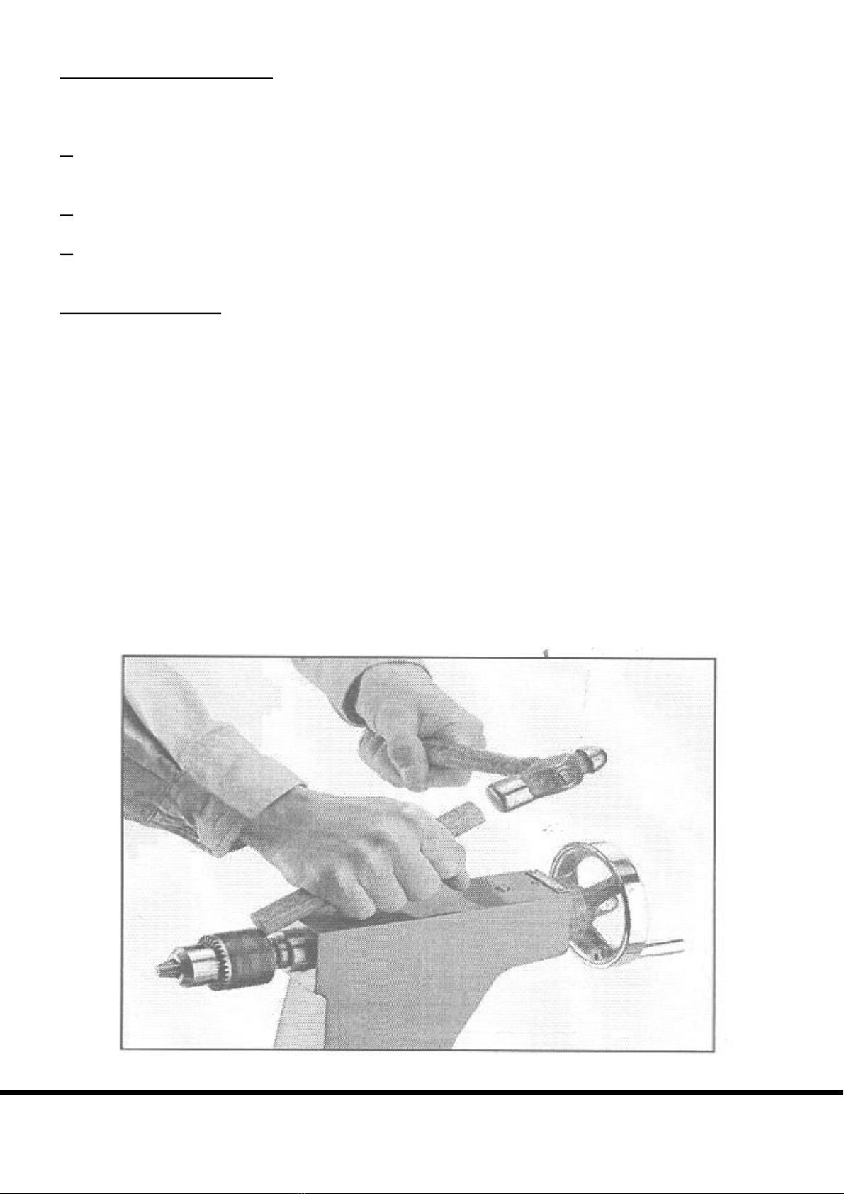
Becausethedrill chuckarbor isthreadedon thesmall end, removalrequiresthe use of amallet and a
woodendowelasinFigures13.Tapalongthebackedgeofthedrillchuckontheleftandthentheright.
Thedrillchuckandarborwillpoploosefromthetailstockbarrel.
Drillchuckarbors withastandardtang(or flat)onthesmall endallow theoperatortosimplyturnthe
tailstock handwheel counterclockwise until the drill chuck and arbor pop loose. Chester UK offers a
varietyofchucksandarbors.Pleaseseeourcurrentcatalogueformoreinformation.
Figure13.Seatingthearboranddrillchuck.
ChesterUKModelB
12
MACHINEVICE
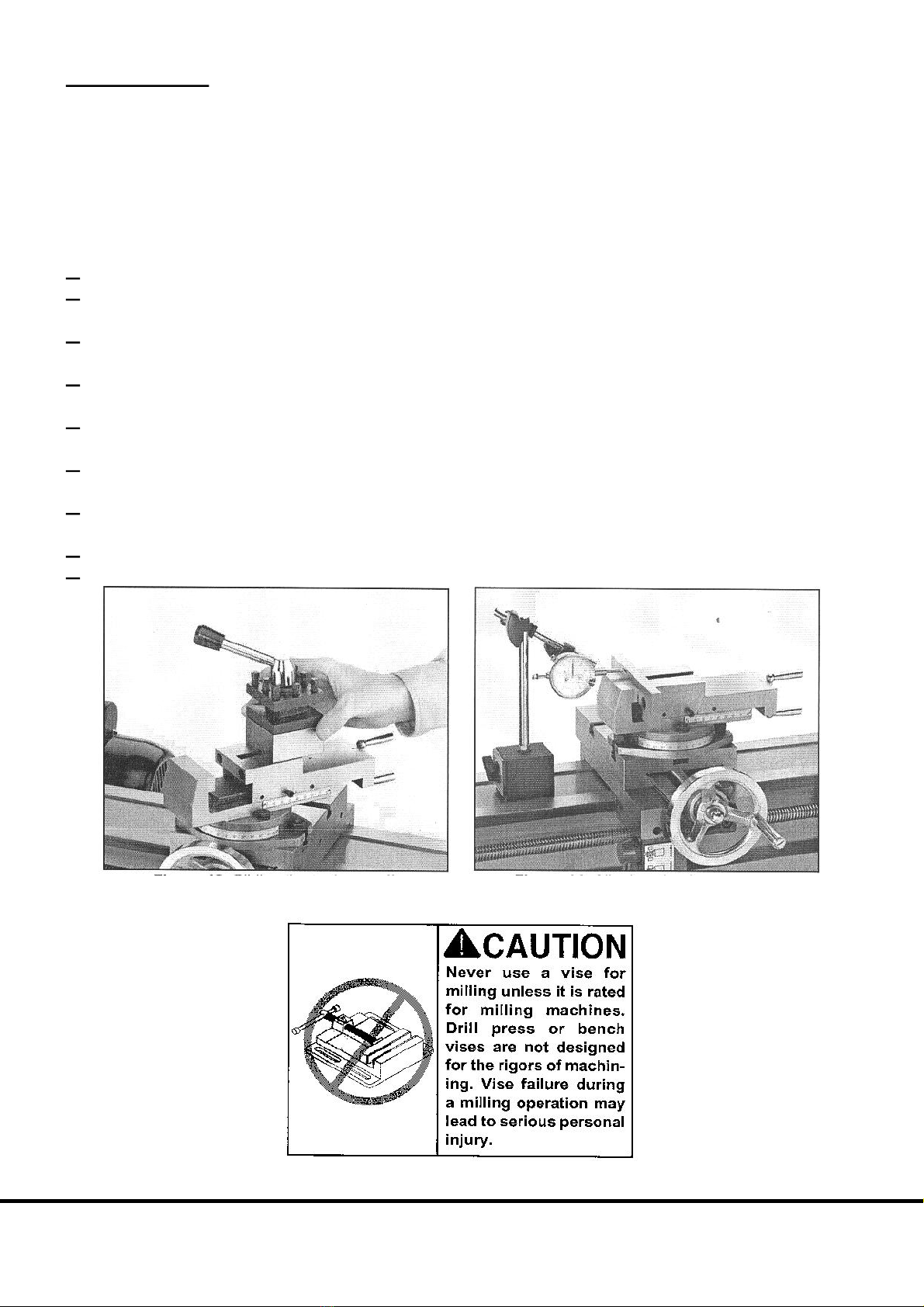
TheModelBcomessuppliedwithamillingvicethatalsoservesasthecompoundforthelathe.The4
waytoolpostmustberemovedbeforeusingthevice.Loosenthelockhandleandslidethetoolpostoffof
thecompound/viceasFigure14.
Themillingvicecanbealignedto1ofthe2axisofthelatheoratanyangledesired.Caremustbegiven
tosettingthevice ifaprecisionangleisneeded.Thefollowinginstructionsaregiventomakethejaws
paralleltothetravelofthecrossslide.
1.Removethetoolpostasdescribedabove.
2.Loosentheswivelboltsonthecompound/vicesoitcanswivelfreely.Pivotthecompound/viceso
thejawsoftheviceareroughlyalignedwiththecrossslide.
3.Mountthedrillchuckintothemillingspindleandsecureanindicatorintoitor,placeadialindicator
mountedtoamagneticbaseonthebedasin Figure15.
4.Positionthecrossslideandapronsotheindicatorpointcontactsthestationaryvicejaworaparallel
mountedintothevice.
5.Movethecrossslidewiththehandwheelandwatchthedial.Notethedirectiontheneedleismoving
onthedialandbyhowmuch.
6.Whenthevicehasmovedsotheindicatorisattheotherendoftheparallel,pivottheviceonehalfthe
amountofmotiondetectedin step6.
7. Move the vice to the starting position and note the difference. Again, pivot the vice one half the
difference.
8.Repeatsteps6 through 8untilthedialremainsstationarywhentheviceismoved.
9.Tightenthepivotboltsonthebaseofthecompound/vice.
Figure14.Slidingthetoolpostoff. Figure15.Aligningviceforprecision.
ChesterUKModelB
13
LATHECONTROLS
LATHESPEEDS
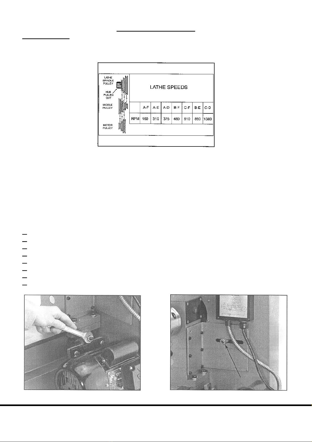
Beforeusingthelathe,thehubontheendofthelathespindlemustbepulledoutasshowninFigure16.
Toeaseengagementofthishub,slowlyrotatethespindlebyhandwhilegentlypullingthehub.
Figure16.Speedchart
Thespeedof the lathe is controlled by the position of thebelts onthepulleys.Thechart inFigure16
showsthevariouscombinationsofbeltpositionsforachievingarangeof6speeds.
Example:
Toselectaspindlespeedof310R.P.M.,placeabeltonthe3
rd sheave(fromtheoutermostsheave)ofthe
middlepulleyandthe2
nd sheaveofthespindle pulley. Place abelt fromthe first sheaveonthemotor
pulleytothefirstsheaveofthemiddlepulley.
Tochangebeltposition:
1.Unplugthemachine.
2.Loosenthetensioningnutlocatedjustabovethemotor.SeeFigure17.
3.Loosenthenutonshaftforthemiddlepulley.SeeFigure18.
4.LiftthemotorandremovethelowerbeltfromtheModelBmotorpulley.
5.Placetheupperbeltinthedesiredposition.
6.Placethetensionbeltinthedesiredpulleys.
7.Pulltensionontheupperbeltwiththemiddlepulleyandtightenthenutloosenedin step3.
8.Tightenthetensioningnutjustabovethemotoruntilthereis¼”deflectionwithmoderatepressure.Do
notovertighten.
Figure17.Tensionnutshown Figure18.Loosenthisnuttoadjustpulley.
ChesterUKModelB
14

FEEDSELECTION
Nevermovethefeedrateleverwhilethemachineisrunning.
TheModelBLathe/Millhas2feedcontrolleverswhichmustbeengagedinordertousethepowerfeed
orthreading feature.TheFeedRateLever,showninFigure19,controlsinternalgearsthatchangethe
feedratebyafactorof2.Turningthelevertoposition“l”willcausetheLeadScrewtoturnattwicethe
rateas whenit isinposition“ll”. Whenthis lever is straight up,thegearing is in neutraland no power
feedisavailable.
Figure19.Feedrateselectionlever
Important
Do not force any lever on the machine. If the lever will not engage, rotate the chuck by hand while
keepinglightpressureontheselector.Asthechuckrotatesitalignsthegearteethinsidetheselectorbox
andtheselectorwillengage.
Figure20.FeedLeverindicatedbyarrow
FEEDLEVER
While the Lead Screw can be placed in neutral with the feed selection lever, another lever allows the
powerfeedingfeatureofthelathetobeturnedonandoff.Whenturnedtotheleft,asinFigure20,the
FeedLeverconnectspowertotheapron.Whenturnedtotheright,theaproncanebefedmanuallyand
thehandcranknolongerturnsbyitself.TheaproncannotbemovedmanuallyunlesstheFeedRateLever
isinneutralortheFeedLeveristurnedtotheright.Pleaseseethecautionbelow.
ChesterUKModelB
15
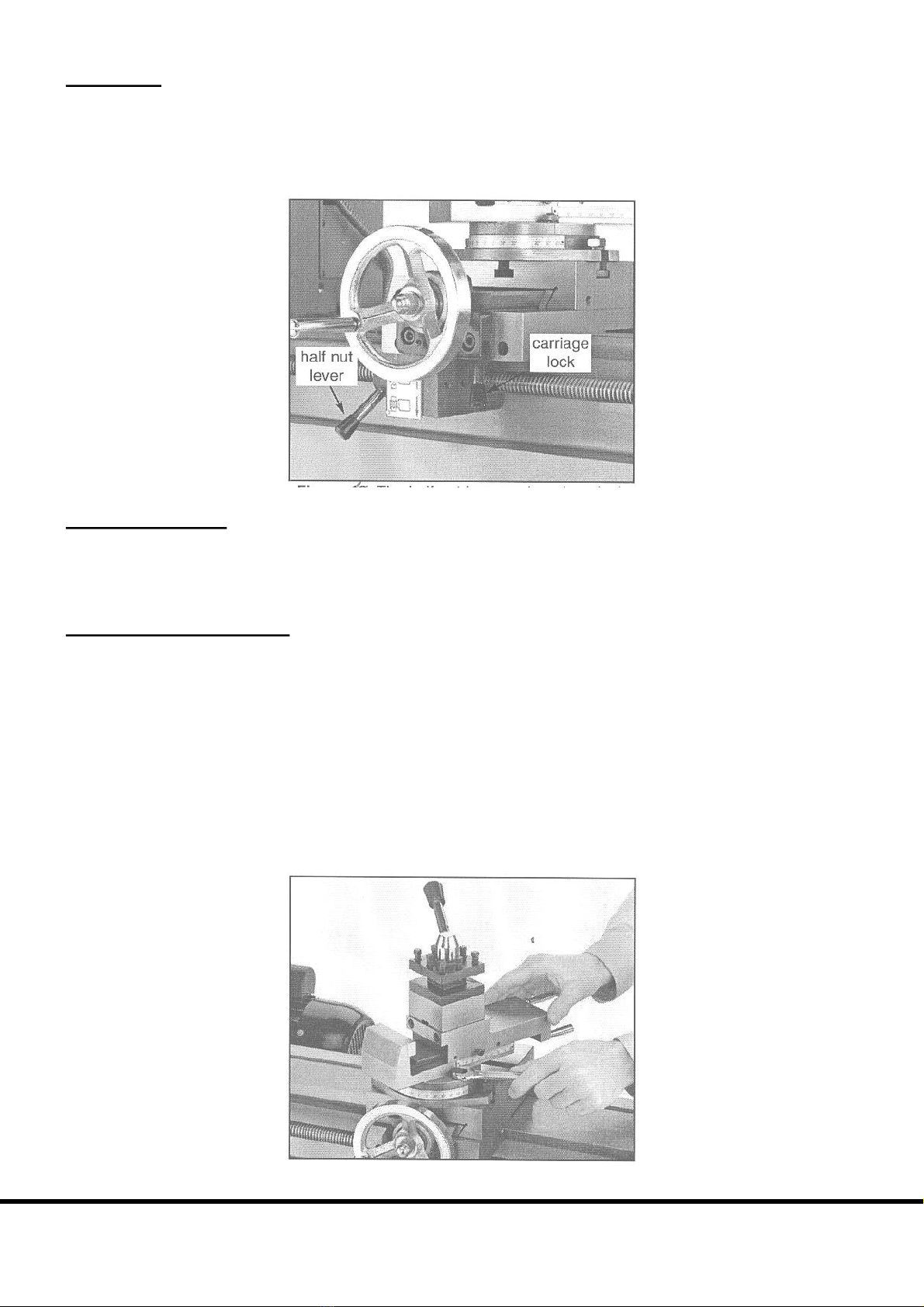
HALFNUT
ThehalfnutleverislocatedunderthelefthandsideapronasshowninFigure21.Thishandlemaybe
engagedanddisengagedwhilethemachineisstillrunningandwhilemakingacut.Movethelevertothe
downpositionandthehalfnutisengaged.BecausethethreadsofthenutandLeadScrewwillnotalways
bealigned,engagingthehalfnutmayrequirewaitinguntiltheyare.Donotforcethehandle.Applylight
pressuretothehandleandwhenthethreadsarealignedthehandlewillengage.
Figure21.Thehalfnutleverandcarriage
CARRIAGELOCK
The carriage lock lever is located under the right hand side of the apron as shown in Figure 21. This
allowsthecarriagetobelockedinplaceforprecisionfacingoperationswhileusingthelatheortomakea
setinamillingoperationmorerigid,amongotherthings.
CARRRIAGECONTROLS
Thelathehas3handlesformanualcontrolofthetoolbitduringmachiningoperations.Onefullturnon
thecrossslideorlongitudinalhandcrankswillproduce0.100”(onetenthofaninch)ofmotion.Thecross
slide and apron crank have dials with divisions showing relative motion. The compound has a direct
readingscaleonitssidewhichiscalibratedin1millimeterincrements.Thefollowingisadescriptionof
eachslideandtheirmeasuringcharacteristics.
Compound Slide – This slide is adjustable to any angle. By loosening the bolts at the swivel base as
shownin Figure22,thecompoundmaypivottoanyanglerelativetotheturningaxisofthelathespindle.
Thisfeatureallowstaperedcutstobeproducedonaworkpiece,andwhensetto60º,ishelpfulincutting
threads, etc. The scale on the side of the slide has divisions in millimeters and is 80 millimeters long.
Eachlinemarks1millimeter(orabout0.03937”).Thetoolpostismountedtothetopofthecompound
slideandwhenremovedallowstheslidetobeusedasavice.
Figure22.Changingtheangleoncompound.
ChesterUKModelB
16

CrossSlide–Thehandwheelmovesthecompoundslideacrossthelathebed.Turningthedialclockwise
movestheslideawayfromtheoperator.Themotionofthisslideisusedforfacingaworkpieceandwhen
advancing a cut for reducing a diameter. The dial has 100 divisions with each division representing
0.001”(onethousandthsofaninch)ofmotionfortheslide.Thelabelabovethedialreportsthateachline
represents0.002”.Itisbesttothinkofthisastheamountofreductionindiameteronthepartperlineon
thedial.Therefore,rotatingthedial10markswillmovetheslide0.010”andmultiplyingthisamountby
0.002”equals0.020”.Therefore,thediameterofthepartwillbereducedby0.020”
Apron–Thelongitudinalmotionoftheaproniscontrolledbythehandcrankattheendofthelathebed.
SeeFigure23.Themotionofthisslideisusedwhencuttingalongthelengthofaworkpiece.Thisslide
canalsobeoperatedwiththepowerfeedfeature.
Figure23.Handcrankfortheapron,
GraduatedDials–Eachdialcanberotatedwithoutturningthehandcrank.Thisishelpfulbecausethe
dialcanbesettozeroafterthetoolbittouchesthepartandthelocationoftheslideandtoolbitwillbe
known.Thegraduateddialcanbeadjustedbyholdingthehandcrankwithonehandandturningthedial
withtheother.
TAILSTOCKCONTROLS
Thetailstockcomessuppliedwithahandwheelwithgraduateddial,barrellock,tailstocklockandoffset
feature.Figure24showsthelocationsofeach.
Tailstock Handwheel – Turning the handwheel advances or retracts the barrel in the tailstock. The
graduateddialonthehandwheelisadjustable.
BarrelLockLever –Thisleverlocksthetailstockbarrelinplace.
TailstockLockLever –Thisleverlocksthetailstockinplaceonthelathebed.
Offset Mechanism – Loosening these bolts allows the tailstock to be offset from centre by turning a
screw.Thisfeaturewillallowtaperturningwhenaworkpieceisheldbetweencentres.
Figure24.Detailoftailstockcontrols
1.TailstockHandwheel 2.BarrelLockLever
3.TailstockLockLever 4.OffsetMechanism
ChesterUKModelB
17
DRILLPRESSCONTROLS
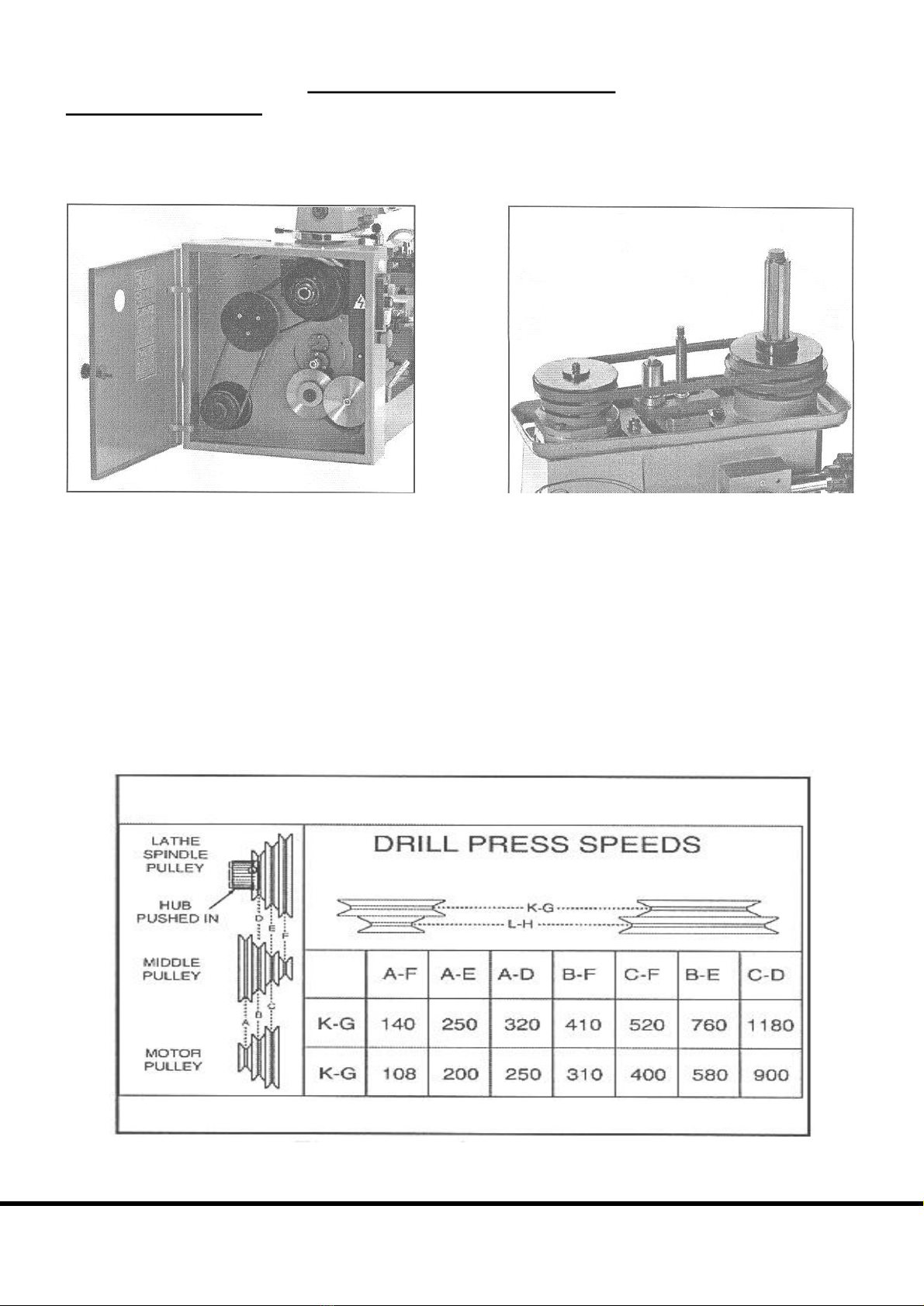
DRILLPRESSSPEEDS
Thespeedofthedrillpressspindleiscontrolledby2groupsofbeltsandpulleys.Thebeltpositionson
theendofthelathecontrolonespeedrange.See Figure25.Thebeltsandpulleysabovethedrillpress
controltheotherrange.SeeFigure26.
Figure25.Lowerpulleysforspeedchanges Figure26.Upperpulleysforspeedchanges
Unplug the Lathe/Mill! Before using the drill press, the hub at the end of the lathe spindle must be
adjusted to the “in” position. See Figure 27. To ease engagement of this hub, slowly rotate the drill
spindlebyhandwhileapplyingpressuretothehub.
Thechartalsoshowsthevariouscombinationsofbeltpositionsforachievingadesiredspeed.
Example:
Toselectaspindlespeedof310R.P.M.,startbymovingthebeltsattheendofthelathe.Movethelower
belttothe“B”position.Movetheupperbelttothe“F”position.Followthebeltchangingproceduresin
thesectiontitledLatheSpeeds.Next,movethebeltlocatedabovethedrillpresstothe“KG”position.
Figure27.Speedchart.
ChesterUKModelB
18
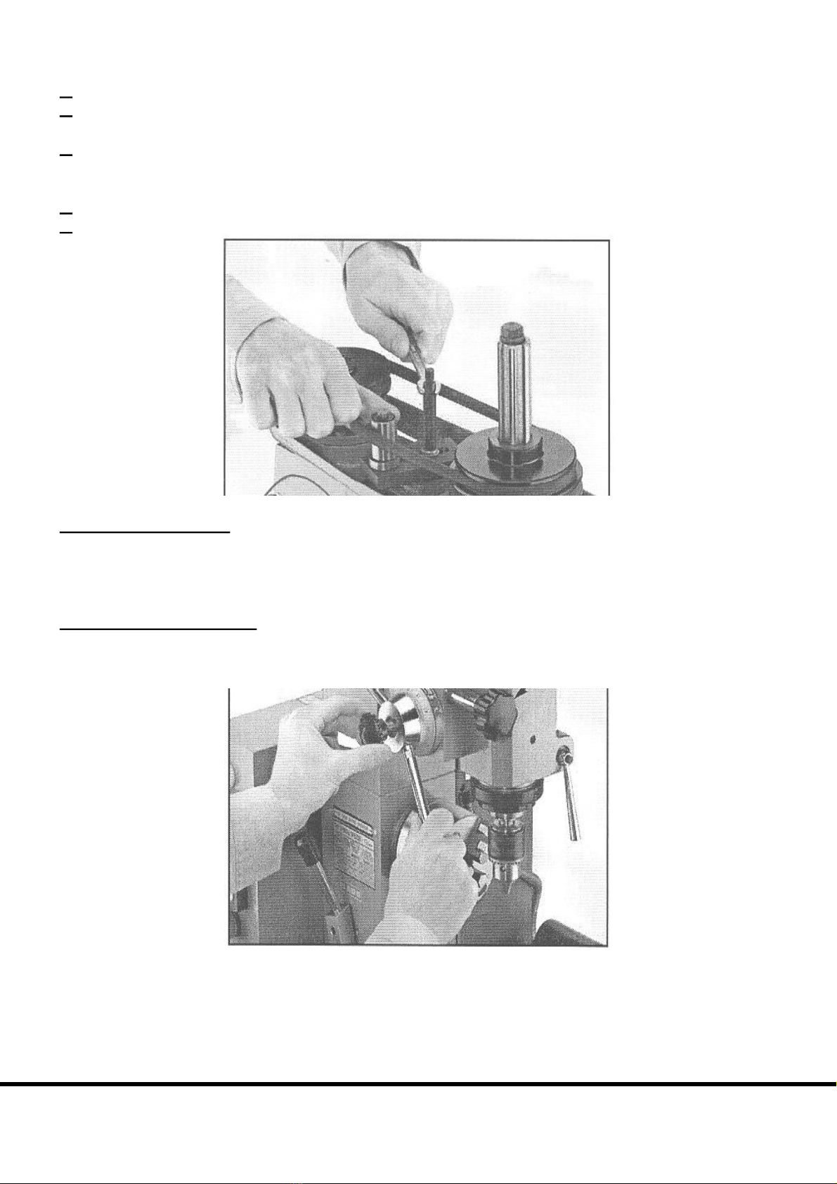
Tochangebeltposition:
1.Unplugthemachine.
2.RemovetheUpperBeltGuard,loosenthecoversecuringthestudandpivotthebelttensionertorelax
tensiononthebelt.SeeFigure28.
3.Whileslowlyturningapulley,rollthebeltupordowntothedesiredsheave.Itisalwayseasiertoroll
offofthelargerpulleyontoasmallerpulley.Donotallowfingerstobecometrappedbetweenbeltand
pulley.
4.Pivotthebelttensioneruntilthebeltistightandsecurethetensionerbytighteningthestud.
5.Replacebeltguard.
Figure28.Loosenstudtopivotbelttensioner.
QUILLLOCKLEVER
TheheightofthespindlecanbelockedwiththeQuillLockLever.SetthedesiredheightwiththeQuill
Leverandturntheleverdown.ThelevercanbeclearlyseenonthebottomrighthandcornerofFigure
29.
FINEFEEDDOWNFEED
TheupanddownmotionofthedrillpressspindleiscontrolledjustlikeanyotherdrillpresswithaQuill
Lever.Butunlikemostdrillpresses,theModelBissuppliedwithaFineDownFeedKnob,indicatedby
thearrowin Figure29.
Figure29.Movethehandlewhiledepressingknob.
Toactivatethisfeature,rotatetheQuillLeverwhiledepressingtheblackknobinthemiddleofthecentre
ofthehubas inFigure29. Theknobwill engage and thespindlewill no longer moveusingtheQuill
Lever.RotatingtheFineDownFeedknobinaclockwisedirectionwillcausethespindletogodown.To
disengagethis feature, rotatetheFineDownFeed knobandpull ontheknob in thecentre ofthe hub.
Rotatingthehandwheelwillalwaysaidinengaginganddisengagingthisfeature.
ChesterUKModelB
19
Table of contents
Other CHESTER U.K. Lathe manuals

Popular Lathe manuals by other brands


IGM
IGM LAGUNA Revo 1836 operating instructions

Bochi Machine Tool Group Co.
Bochi Machine Tool Group Co. CS6140 Series Operator's manual

LNS
LNS HYDROBAR SPRINT 555 Troubleshooting and Spare Parts Manual

Jet
Jet ZH Series Operation and maintenance instructions

Teknatool
Teknatool NOVA DVR XP instruction manual

MiniMax
MiniMax T 124 instruction manual