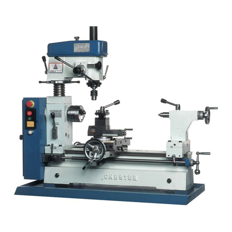
CHESTER U.K. Cobra User manual

Contents
1. Introduction 2
2. Health&Safety 35
3. MachineSpecification 6
4. Testing 7
5. Operation 816
6. Maintenance 17
7. OilingPoints 18
8. ChangeGearTable 19
9. PartsList&Diagrams 2025
10.WiringDiagrams 2627
11.CEDocument 28
ChesterUKCobraLathe
1

Introduction
ChesterUKLimitedisaspecialistcompanythathasbeensupplyingthemachinetoolindustryfor
over15years.TheChesterUKHeadOfficecomprisesofa30,500sq.ftfactorycompletewithofficesand
a showroom. Specialising in conventional machine tools, Chester has built a reputation for quality and
reliability,whichishighlyregardedinthemachinetoolindustryandthemodelengineeringmarket.
Thereareseveraldivisionswithin thecompany;Export, Education,ModelEngineering&UKSales,all
withdedicatedsalespersonnelwhoaretrainedtoansweryourquestions.
When buying from Chester you can be assured of a complete backup service with mechanical and
electricalengineersthatareavailabletogiveadviceifrequired.
StockisalargepartofanybusinessandChesterhavealwaysinvestedsubstantiallyinbuildingalarge
quantity of machines and spares, ready to satisfy customer requirements. Chester UK has one of the
largest stocks ofconventional new machinesand accessories within Great Britain. Please taketime to
visitourwebsite: www.chesteruk.net
ChesterUKCobraLathe
2

Health&Safety
Aswithallmachinerytherearecertainhazardsinvolvedwiththeoperationanduseofthelathe.
Using the machine with respect and caution will considerably lessen the possibility of person injury.
However, if normal safety precautions are overlooked or ignored, personal injury to the operator may
result.
Thismachinewasdesignedforcertainapplicationsonly.Westronglyrecommendthatthemachineisnot
modified,and/orusedforanyapplicationotherthanwhichitwasdesigned.Ifyouhaveanyquestions
relativetoitsapplicationdonotusethemachine,untilyouhavefirstbeenincontactwithChester
UK.
The lathe may not arrive with a power socket or plug. In the event of this happening, please inform
ChesterUKonTel:(01244)531631.
Safetyrulesforalltools
User
1. Wearcorrectapparel
Nolooseclothing,gloves,rings,braceletsorotherjewellerytogetcaughtinmovingparts.Non
slipfootwearisrecommended.Wearprotectivehaircoveringtocontainlonghair.
2. Alwaysweareyeprotection
Refer to ANSLZ87.1 standard for appropriate recommendations. Also use face and / or a dust
maskifthecuttingoperationisdusty.
3. Don’toverreach
Keepaproperfootingandbalanceatalltimes.
4. Neverstandonatool
Seriousinjurycouldoccurifthetoolistippedorifthecuttingtoolisaccidentallycontacted.
5. Neverleavethetoolrunningunattended
Turnpoweroff.Leavetooluntilitcomestoacompletestop.
6. Drugs,alcoholandmedication
Donotoperatethetoolwhileundertheinfluenceofdrugs,alcoholoranymedication.
7. Makesurethetoolisdisconnectedfromthepowersupply
Whilemotorisbeingmounted,connectedorreconnected.
8. Always
Keephandsandfingersawayfromanymovingparts.
9. Stop
Themachinebeforemovingchips.
10.Shutoff
Powerandcleanthelatheandworkareabeforeleavingthemachine.
Useofthemachine
1. Removeadjustingkeysandwrenches
Form a habit of checking to see that keys and adjusting wrenches are removed from the tool
beforeturningit‘on’.
2. Don’tforcethetool
Itwilldothejobbetterandbesaferattherateforwhichitwasdesigned.
3. Usetherighttool
Don’tforcethetoolorattachmenttodoajobforwhichitwasnotdesigned.
4. Securework
Useclampsoravicetoholdworkwhenpractical.It’ssaferthanusingyourhands,andfreesboth
tooperatethemachine.
ChesterUKCobraLathe
3

5. Maintaintoolsintopcondition
Keeptoolssharpandcleanforthebestandsafestperformance.Followinstructionsforlubricating
andchangingaccessories.
6. Userecommendedaccessories
ConsultChesterUKforrecommendedaccessories.Theuseofimproperaccessoriesmaycause
hazards.
7. Avoidaccidentalstarting
Makesuretheswitchisinthe‘OFF’positionbeforeplugginginpowercord.
8. Stop
Themachinebeforeputtingmaterialinthevice.
9. Always
Havestockfirmlyclampedinthevicebeforestartingthecut.
10. Groundalltools
If the tool is equipped with a threeprong plug, it should be plugged into a threehole electrical
receptacle.Ifanadapterisusedtoaccommodateatwoprongreceptacle,theadapterplugmust
beattachedtoaknownground.Neverremovethethirdprong.
Adjustment
Make all adjustments with the power off. When assembling follow the manuals instructions, this
willensurecorrectinstructionandasafestructure.
Workingenvironment
1. Keeptheworkareaclean
Clutteredareasandbenchesinviteaccidents.
2. Don’tuseinadangerousenvironment
Don’tusepowertoolsindamporwetlocations,orexposetorain.Keeptheworkareawelllit.
3. Keepchildrenetcatasafedistance.
Allchildrenetcshouldbekeptatasafedistancefromtheworkarea.
4. Don’t
Install&usethismachineinanexplosivedangerousenvironment.
Maintenance
1. Disconnect
Machinefromthepowersourcewhenmakingrepairs.
2. Checkdamagedparts
Beforefurtheruseofthetool,aguardorotherpartthatisdamagedshouldbecarefullycheckedto
ensure that it would operate properly and perform its intended function check for alignment of
movingparts,bindingofmovingparts,breakageofparts,mountingandanyotherconditionsthat
may affect its operation. A guard or other part that is damaged should be properly repaired or
replaced.
3. Disconnecttools
Beforeservicingandwhenchangingaccessoriessuchasbladesbits,cutters,etc.
4. Toprevent
Thecorrosionofmachinedsurfaceswhenasolubleisusedascoolant,payparticularattentionto
wipingdrythesurfaceswherefluidaccumulatesanddoesnotevaporatequickly,suchasbetween
themachinebedandvice.
ChesterUKCobraLathe
4

SafetyDevice
1. Interlockswitchonpulleycover.Assoonasthepulleycoverisopen,themachinewillcometo
a stop with the function of this switch. Do not remove this switch from the machine for any
reason,andcheckit’sfunctionfrequently.
2. Interlockswitchoncuttingarea.Assoonasthepulleycoverisopen,themachinewillcometo
a stop with the function of this switch. Do not remove this switch from the machine for any
reason,andcheckit’sfunctionfrequently.
ChesterUKCobraLathe
5

MachineSpecification
DrillingCapacity 10mm
EndMillCapacity 10mm
FaceMillCapacity 20mm
SpindleStroke 30mm
Throat 140mm
TableWorkingSurface 50x145mm
LongitudinalTravel 180mm
CrossTravel 90mm
Max.DistanceSpindleToTable 220mm
No.OfSpindleSpeeds Variable
RangeOfSpeeds 1002000rpm
SpindleTaper MT2
Motor 150W
Supply 240V50Hz
Weight(nw/gw) 47/60Kg
Dimensions(LxWxH) 540x380x680mm
ChesterUKCobraLathe
6

Testing
Whenthelatheismountedtoyoursatisfaction,proceedasfollows:
a) Closethechuckjaws.
b) Checkthetailstockis‘nipped’andthebarrellockistightened.
c) Checkalllooseitemsareremovedfromthelathe.
d) Setthesaddleapproximatelymidwayalongthebed.
e) PresstheEmergencyStopButtonIN(EmergencyStopON).
f) ChecktheAutofeed/ManualLeverissettomanual(Handlogo).
g) Closethechuckguard.
h) CheckthespeedcontrolisswitchedOFF(fullyanticlockwise).
i) ChecktheForward/Off/ReverseSwitchisintheOFFposition.
j) ConnectthemachinetothemainssupplyandswitchpowerON.
k) TurnEmergencyStopswitchtotherightandallowittospringoutandreset.
l) ChecktheGreenPowerLEDisilluminated.
m) TurntheSpeedControlSwitchOn(ClicksOn).
n) ChecktheAmberLED(FaultLight)isilluminated.
o) SwitchtheSpeedControlSwitchOFF(ClicksOFF)andtheAmberLEDisnowoff.
p) SelectForwardontheForward/Off/Reverseswitch.
q) TurntheSpeedControlSwitchOnandadvanceuntiltheChuckstartstorotate.
r) LifttheChuckGuard;checkthespindlestopsandtheAmberfaultLEDilluminates.
s) ResettheChuckGuard,checkthespindledoesNOTrestartandtheAmberfaultLEDremains
On.
t) TurntheSpeedControlSwitchOFF,andthattheAmberLEDgoesoff.
u) TurntheSpeedControlSwitchON,advanceuntilthespindlestartstorotate.
v) Overaperiodofapproximately5minutesadvancethespeedinstagestomaximum,runat
maximumforatleast2minutes,checkthatthereisnothinguntoward(noexcessivevibration,
speedprogressionissmoothetc).
w) Ifalltheabovechecksarecorrect,stopthespindle;selecttheAutofeedfunction(ifnecessary
‘jog’theleadscrewhandletoenablethegearstomesh).Switchonandadvancetoa
reasonablespeed,checkthesaddledrivessmoothlytowardsthechuck.
x) Stopthespindle,selectreverse,switchONandadvancetoareasonablespeed,checkthe
chuckdrivessmoothlytowardsthetailstock.
y) Ifalltheabovechecksarecorrect,thefinalcheckistosetthespindlerunning,thenhitthe
EmergencyStopswitch.CheckthespindlestopsandallpowerindicationsgoOFF.
z) Yourlatheisnowreadyforuse.Enjoy.
ChesterUKCobraLathe
7

Operation
Definitions
MainAxis
Thisistheaxisestablishedthroughthespindleoftheheadstock.Itishorizontaltoandparallelwiththe
lathebedalongitslength,asdescribedbythesaddle
WorkAxis
This is the axis established by the work piece;it is horizontal to, but not necessarily parallel with, the
lathebed,alongitslength.
TraverseAxis
Thisistheaxisdescribedbythetraverseslidewhenitisbeingmovedindependentlyofthesaddle.Itis
perpendiculartothemainaxisinthehorizontalplane.
CompoundAxis
Thisistheaxisdescribedbythecompoundslide,iffitted,whenitisbeingoperatedindependentlyofthe
traverseslideandthesaddle.
Headstock
The‘engineblock’ofthelathe,supportsthemotor,thespindle,andthecoverforthechangegears,the
drive belt and the driven end of the leadscrew. It also mounts the control panel for the motor and the
selectorfortheleadscrew.
ChangeGearCover
Protectivecover,enclosingthemotorpulley,thedrivepulley&drivebeltandthechangegear.
Motor
220Vd.c.motor.
MountingFlange
The mountingflangeisintegralwith thespindle andmountsallthematerialcarriers(chucks,faceplate
etc), it is bored with a No.2 morse taper to accept the headstock centre. The boring is then carried
through the complete length of the spindle (10.5mm clear) to allow long lengths of round bar to be
machined. Your MicroLathe is supplied with a chuck adaptor plate and chuck already fitted to the
mountingflange.
ChuckSafetyCover
Aclearacetatecovermountedonapivotbaronthereartopfrontfaceoftheheadstock.Itcanbetipped
out of the way to access the chuck when it is stationary, and repositioned over the chuck during
operation.Itissafetyinterlocked,ifitisnotinpositionthemotorwillnotrun,orthemotorwillstopifitis
movedwhilstthespindleisturning.
MotorControlPanel
PowerOnLED
GreenLEDthatindicatesthatpowerisavailabletothemotor.i.e.mainsisapplied,fuseisintact
andtheEmergencyStopswitchisnotactivated.
ChesterUKCobraLathe
8

FaultLED(markedUNNORMAL)
Amber LED that indicates that there is a fault or an incorrect control sequence. e.g. the chuck
guard interlock has been activated or the speed control is activated without forward or reverse
directionbeingselected.TheMotorwillnotrunifthefaultLEDisilluminated.Ifthesafetyinterlock
is activated, if the safety interlock will remain in force until the interlock is reset and the start
sequenceisreinitiated.
FuseCap
Accesscapforthe20mmfusecartridge(1Amp250V).
SpeedControlKnob
Roundraisedridgeknobconnectedtothecircuitthatcontrolsthemotorspeed(1002000rpm).
Forward/Off/ReverseSwitch
Three position switch that controls the direction of the rotation of the spindle. Forward indicates
that the spindle is turning toward the operator; Reverse, the spindle is turning away from the
operator.ThecentreOffpositioninhibitsthespindlefromturningineitherdirection,undermotor
drive.
EmergencyStopSwitch
RedDomedMushroomswitch;ifpresseditremovesallpowertothemachine.Itisa ‘knockoff,
stayoff’switch.Toresettheswitchthedomedheadmustbeturnedclockwise,whichwillallowthe
switchtounlatchand‘springout’andresetitself.
ChesterUKCobraLathe
9

(Chuck&safetycoverremovedforclarity)
ChesterUKCobraLathe
10

LeadscrewSelector
Aroundcentreribswitch/lever,whichallowsselectionoftheleadscrewto‘Autofeed’,i.e.drivenbythe
changegeartrain(indicatedbyatriangularwaveformsign),ormanually,i.e.drivenbythehandleonthe
endoftheleadscrew(indicatedbya‘hand’logo).
LatheBed
Solid cast, machined bed. The face machining gives two flat bearing surfaces, whilst the ancillary
machininggivesadovetailformtothebed,andformsarigidstablelocatingandguidingsystemforall
themachinescomponents.
Saddle
Maincastingthatisprecisionmachinedtomarrywiththelathebed.Itmovesparalleltothemainaxis.It
mountsthetraverseslide.The‘gib’stripsetintherearofthesaddledovetailmaintainstheaccuracyof
thefitofthesaddletothebed.
TraverseSlide
Mountedona‘dovetail’landmachinedontothetopofthesaddle.The‘gib’stripsetintherighthandside
ofthetraversedovetailslidemaintainstheaccuracyofthefitoftheslide.Thebedofthetraversehastwo
‘T’slotsmachinedintoittoallowthemountingofthetoolpostorthecompoundslideaccessory.
TraverseSlideControl
Awheelandrodhandle,mountedonashaftthatisanchoredintoahousingmachinedinthefrontofthe
traverseslide,theshaftis threadedandis engagedina dogfixedtothesaddle,enablingthe traverse
slidetobedrivenbackandforthacrossthesaddleperpendiculartothemainaxis.Thereisagraduated
ring(thimble)ontheneckofthehandletoallowthemovementoftheslidetobemeasured.
ToolPost
A doublesided tool post. Each tool position has 2 securing bolts to clamp the tool in place. One tool
mountinghasafixed‘bed’theotherhasa‘rocking’bedinacurvedseatingtoallowthetooltobetilted
slightlyforwardorbacktoallowprecisetoolheightstobeachieved,withoutthenecessityforfineshims.
Thetoolpostissecuredintoeitheroneofthe‘T’slotkeeper.Thetoolpostisnotkeyedintothe‘T’slotso
itcanbeturnedtoanyanglebeforebeinglockedinposition.
ChesterUKCobraLathe
11

ChesterUKCobraLathe
12

GearChangeCoverKnob
Areededknobscrewedintothefrontoftheheadstock,itlocatesinaslotinthechangegearcover,and
isusedtosecurethecovertoallowittobesungopen.
Tailstock
Amachinedcastingthataccuratelyfitstothelathebed.Itcarriesthetailstockbarrel.Thetailstockbarrel
ismachinedwithaNo.1MT,whichallowstheaccessoriestobemounted(centres,drillchucks,reamers
etc).Thetailstockispositionedonthebedbyaclampmechanismatthefrontofthetailstockbody.The
twocapheadboltsinthefrontflangeofthecastingtightentheclamp.Thetailstockiscapableofbeing
offsettoallowfortaperturning.Theoffsetlockingscrewisontherightofthetailstock.
TailstockBarrelControl
Wheel androd handle that controls the backward and forward movement of the barrel in the tailstock.
Thebarrelhasatravelof22mm,toallowthetailstocktoolingtobebroughtintocontrolledcontactwith
theworkpiece;thisisindicatedona coarsescaleengravedonthebarrelitself.Thescaleindicates–0
andthen20plustwo(x1mm)divisions.Thesupplied tailstock centrewill self ejectat–0.Thetailstock
control has a graduated ring (thimble) mounted on the neck of the handle so that the amount of
movementcanbemeasured.
TailstockBarrelLock
Small‘petal’knobthatlocksthebarrelinplaceonceithasbeenmovedintotherequiredposition.
Leadscrew
Theleadscrewisathreadedshaftthatisanchoredintoahousingmachinedintotheendofthelathebed.
Theshaftrunsvirtuallythroughthecentreaxisoftheundersideofthebed,andisengagedinadogfixed
totheundersideofthesaddle,enablingthesaddletobedrivenbackandforthalongthemainaxisofthe
bed.Thefixeddogiswellsupportedfromthefrontapronofthesaddle,andcombinedwitheffectofthe
centralizedaxisoftheleadscrew,resultsinaverysmooth‘judder’freemovement.Theleadscrewcanbe
driven from either end, from the headstock end, via the change gear train, for auto feed and thread
cutting,ormanuallybytheleadscrewdrivehandle.
Note
The leadscrew is permanently engaged into the saddle dog. Any movement of the leadscrew is
transmittedtothesaddle.
LeadscrewDriveHandle
Wheel and rod handle locked onto the end of the leadscrew shaft. Turing the handle will turn the
leadscrewanddrivethesaddlebackandforthalongthemainaxisofthelathe.Thereisagraduatedring
(thimble)ontheneckofthehandletoallowthemovementofthesaddletobemeasured.
MotorSecuringBolts
Twocapheadboltsscrewthroughthechangegearcompartmentbulkheadandintothemotorflange.The
holesthroughthebulkheadareelongatedtoallowthemotortobemovedslightlytomaintainthedrive
belttension.
LeadscrewOilingPoint
Thisisasmallholesituatedbetweentwocapheadboltsonthelowerrightfaceofthesaddleapron.The
oil gallery gives direct access to the leadscrew dog, and enables oil to be spread onto the leadscrew
(whichismainlyobscuredbeneaththelathebed.)
MotorBrushCaps
Twobrushcapslocatedtopandbottomofthemotor;theyareaccessedbyremovingthesplashguard.
ChesterUKCobraLathe
13

ChesterUKCobraLathe
14

ChesterUKCobraLathe
15

YourCobraLathehasbeenfactorysetandadjusted,however,duringitslifetimeyoumay
find occasion whereby the lathe needs adjusting to maintain its accuracy and optimum
performance.Theseadjustmentscanbemadeasfollows:
Saddle&TraverseSlideAdjustment
Thesaddleandthetraverseslidearemountedoverdovetailsections.Inordertomaintainthe‘tightness’
of the fit; between the sloping surface of the component and its matting surface a gib strip has been
inserted(Attherearofthesaddle,andtotherighthandsideofthetraverseslide).
Toadjustthegibstrips,loosenthelocknutsandscrewtheadjustingscrewIN(No.4forthetraverseslide
andNo.3forthesaddle).‘Nipping’thecomponenttighttoitsbedway.Tightenallthescrewstothesame
torque.Check,usingthefeedhandles,thatthesaddle/slidearelockedinplace.
Unscreweachadjustingscrewbyquarterturn,holdthescrew(socketgrubscrew)inpositionandtighten
the locknut. Check the component now moves smoothly along its bed, using the feed handles. If not,
carry outthesameprocedure,unscrewby athirdturnthistime,etc,ifthemovementwastootight;by
lessthanaquarteretc.,ifthemovementbecametoloose.
Repeattheprocedureuntilthemovementsaresmoothandtight.N.B.Alwaystightenthelocknutsbefore
testing.
FeedScales
The two thimbles that are mounted on the feed shafts of the leadscrew and the traverse feed should
move freely with the motion of the handle and not slip. The thimbles can be turned, using more force,
independently of the handle in order to set a predetermined start or finish point. If the thimbles are
‘slipping’i.e.notmaintainingtheirplacerelativetothehandle,whilstthehandleisturning;thecauseis
almostinevitablydirt,swarfetal.,betweenthepressureplateandthethimble.Torectifythis,undothe
nut and washer securing the handle to the shaft, remove the hand wheel, and then remove the keyed
collarandthimbleassembly.Takecarethatthekeydoesnotdropoutoftheshaft.Graduallyseparate
the thimble from the keyed collar; by twisting and turning, until there is sufficient space to clean the
matingsurfaces.
BE WARNED The friction drive between the collar and the thimble is effected by a wire spring
(likepartofacirclip)thatishousedinagrooveinthecollarandrubsagainsttheinsideboreof
thethimble.Ifthecollarisseparatedtoofar,thegrooveandthespringareexposed.Thespring
canfalloutandifnotlost,itisawkwardtorecompressthespringsothatthethimblewillslide
completelybackontothecollar.
Oncethematingsurfacesareclean,matethekeyandthekeywayandfitthecollar/thimbleassemblyto
theshaft.Refitthewasher andthesecuringnut, andtighten.Tightenuntilthehandwheel,thimble and
collar assemble are too tight to move. Undo the securing nut a quarter turn and check that the drive
handlerotatesfreelyandthereisnotexcessivebackwardandforwardplayintheshaft(Thehandleetc,
formsonesideofthedrivescrewanchorintotheslide).
ChesterUKCobraLathe
16

Maintenance
TheLatheisaprecisiontool.Inordertomaintainthisprecisionand prolongitsusefullife,itis
advisedthatyoufollowtherecommendeddailyandperiodicmaintenancetablesprintedbelow.
Daily
Carry out a visual inspection. Repair any damage immediately. Minor damage to the beds should be
takenoutwithanoilstone.
Movethesaddleandthetraverseslidebackandforthbyhand;checkthatthemovementissmooth.
Spreadalightfilmofoiloverthebedandthetraverseslidebed.
Directlysprayoilontheleadscrewaftereveryuse.
Ifthelatheissubjecttoprolongeduse,oiltheleadscrewandbearingsevery34hours(Theleadscrew
islocatedunderneathandrunstheentirelengthofthelathebed).
DailyAfterUse
1. Cleanallswarfandchipsawayfromthemachinebed,slidesurfaces,andthetoolpost.
2. Exercisetheslidesandensurenoswarfetc.,islodgedinthedriveshafttunnels.Ifyouhave
beenusingacoolantmakesurethemachineisthoroughlydriedoff.
3. Checkthetool,ensureitisusableforthenexttime,ifnotresharpenorreplacethetooltip.
4. Lightlysprayoiloverallthemachinesbedsandsurfaces,andthetailstockbarrel.
5. Cleanandlightlyoilanytoolsyoumayhavebeenusing(centres,drillchucks,spanners,chuck
keysetc)andputthemaway.
6. SwitchOFFthepowersupply.Disconnecttheplug.
7. Coverthemachineoverwithadustcloth.
Weekly
1. Movethetraverseslidefullybacktogiveaccesstothetunnel,blowouttomakesureallswarf
is clearedawayandheavilysprayoil in thetunnel, exercisethe slideto workthe oilintothe
drivethreadandtolubricatethedog.
2. Sprayoiltheslideandthelathebed,exercisethesaddleandtheslidetospreadtheoiltoall
surfaces,bothhiddenandvisible.
3. Sprayoilunderthebedontotheleadscrew.
4. Check the movement of the saddle and the traverse slide, check it is smooth and ‘tight’, if
necessaryresetthegibstrips.
Monthly
Checkthebelttension.Ifnecessaryresetthebelttensionbylooseningthetwomotorsecuringcaphead
bolts,retensionthebeltandresecurethebolts.
Every6Months
Because the D.C. motor has a heavy permanent magnetic field, it is advisable to dismount the lathe
every6months,removethesplashguardandremovealltheswarfthatmayhavefounditswayintothe
motorhousing.
ChesterUKCobraLathe
17

OilingPoints
ChesterUKCobraLathe
18

ChangeGearTable
ChesterUKCobraLathe
19
Table of contents
Other CHESTER U.K. Lathe manuals

