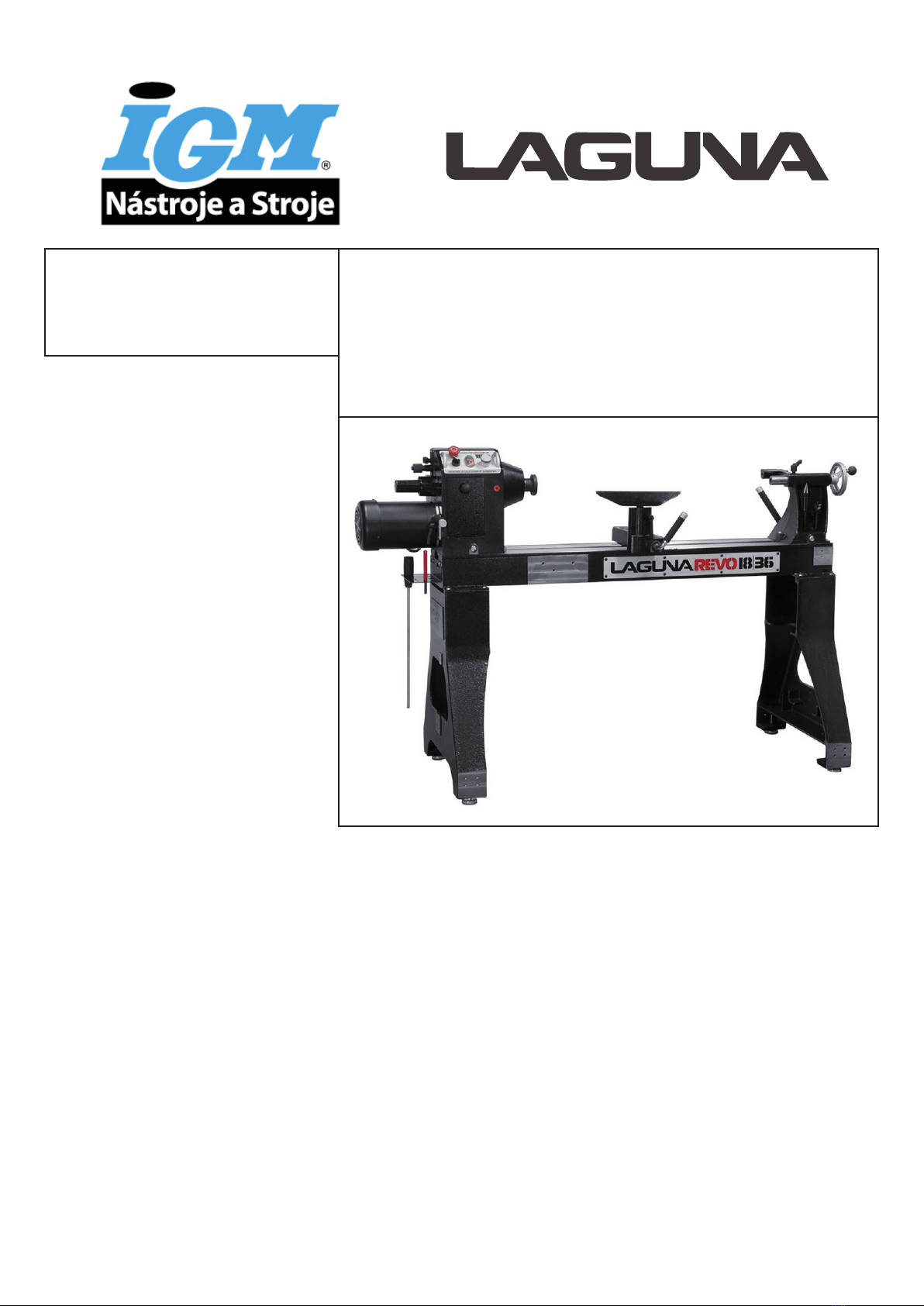
IGM LAGUNA Revo 1836 User manual
Manufacturer / Hersteller / Výrobce / Výrobca / Gyártó / Producent:
Laguna Tools Inc
2072 Alton Pkwy
Irvine, CA 92606,
USA
Phone: +1 800-234-1976
Website: www.lagunatools.com
Distributor / Distributor / Distributor / Distribútor / Forgalmazó / Dystrybutor:
IGM nástroje a stroje s.r.o.
Ke kopanině 560, 252 67, Tuchoměřice, Praha-západ
Česká republika
Tel: 220 950 910
www.igm.cz
MLAREVO 1836 2020-01
Woodturning lathe
Drechselbank
Soustruh na dřevo
Sústruh na drevo
Faesztergapad
Tokarka do drewna
REVO 1836
man_151-1836_A4ob_Soustruh na dřevo_EN+DE+CZ+SK+HU+PL_v1.7
EN Operating instructions
(Translation of original)
DE Gebrauchsanweisung
(Übersetzung der Originalgebrauch sanweisung)
CZ Návod k obsluze
(překlad původního návodu)
SK Návod na obsluhu
(preklad pôvodného návodu)
HU Használati útmutató
(eredeti használati útmutató fordítása)
PL Instrukcja obsługi
(tłumaczenie oryginalnej instrukcji)

-2-www.igmtools.com
CE-Declaration of Conformity
Product:Woodturning lathe
REVO 1836
Type number: MLAREVO 1836
Brand: Laguna
Manufacturer:
Laguna Tools Inc
2072 Alton Pkwy, Irvine, CA 92606, USA
Declare under our sole responsibility that this product is in conformity with the following directives:
- Machinery Directive 2006/42/ES
- Low Voltage Directive 2014/35/ES
- Electromagnetic Compatibility Directive 2014/30/ES
Designed in conformity with:
** EN 1870-19:2013
EN60204-1:2006+AC:2010
Technical documentation processed by:
TUV Rheinland LGA Products GMBH
Certicate number: BM50418591 & BM50418592
2019-12 Ivo Mlej, CEO
IGM nástroje a stroje s.r.o., Ke kopanině 560, 252 67 Tuchoměřice, Česká republika

-3-www.igmtools.com
Contents
1. Declaration of conformity
1.1 Warranty
2. About this manual
3. Specications
3.1 Parts of the machine
3.2 Technical data
3.3 Noise emission
4. General safety
4.1 Safety Rules
4.2 Electrical connections
5. Receiving your machine
5.1 Unpacking and transport
5.2 Receiving the lathe
5.3 Locating your machine
6. Assembly and setup
6.1 Assembling the legs to the bed of the lathe
6.2 Cleaning the machine
6.3 Fitting the rotating centre
6.4 Fitting the drive centre into the head stock
6.5 Fitting the face plate
6.6 Lathe controls
6.7 Variable speed adjustment knob
6.8 High / low speed
6.9 Indexing the spindle
7. Maintenance
8. Troubleshooting
1. Declaration of conformity
We declare that this product is in
compliance with the Directives and Standards
on page 12 of this manual.
1.1 Warranty
IGM Tools & Machinery strives to always
deliver high-quality machinery. The warranty is
governed by the valid terms and conditions of
IGM Tools & Machinery available at
www.igmtools.com.
2. About this manual
This manual is intended to thoroughly cover the
setup up, maintenance, and proper adjustments
of your new purchase. Aside from the
proceeding general safety considerations,
this manual DOES NOT cover woodworking
or metalworking techniques that are possible
with this product and the appropriate safety
precautions necessary for safe practices.
3. Specications
Wood turning lathes are typically used to shape
wood into cylindrical proles. Objects made on
a wood lathe include such items as furniture
legs, lamp posts, baseball bats, bowls and
other ornamental forms. Wood lathe tooling
consists of xtures and securing devices for the
work piece, a moveable tool rest, and hand-
held cutting tools.
3.1 Parts of the machine
The lathe consists of a number of major parts,
which are discussed in this manual. Take the
time to read this section and become familiar
with the machine.
Identication
There is a plate at the back of the machine
listing all the manufacturing data, including
the serial number, model, etc.
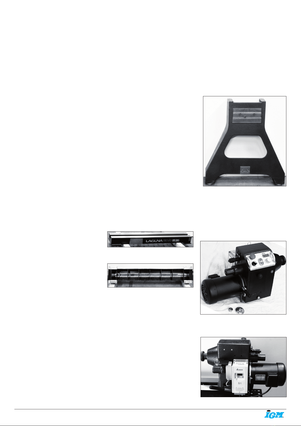
Lathe Bed
The bed is a heavy steel welded construction.
Pic. 1
Underside of lathe bed
Pic. 2
Lathe legs
The Legs are cast iron, and their heavy
construction gives the machine a low centre of
gravity and ensures that it is very stable. The
legs are supplied with adjustable feet to allow
the machine to be levelled.
Legs with adjustable feet assembled.
Pic. 3
Head stock
The head stock is cast iron and houses the
variable speed control and motor. The spindle
can be locked in 14 / 36 and 48 positions.
Headstock removed from the bed
Pic. 4
Headstock attached to bed
Pic. 5
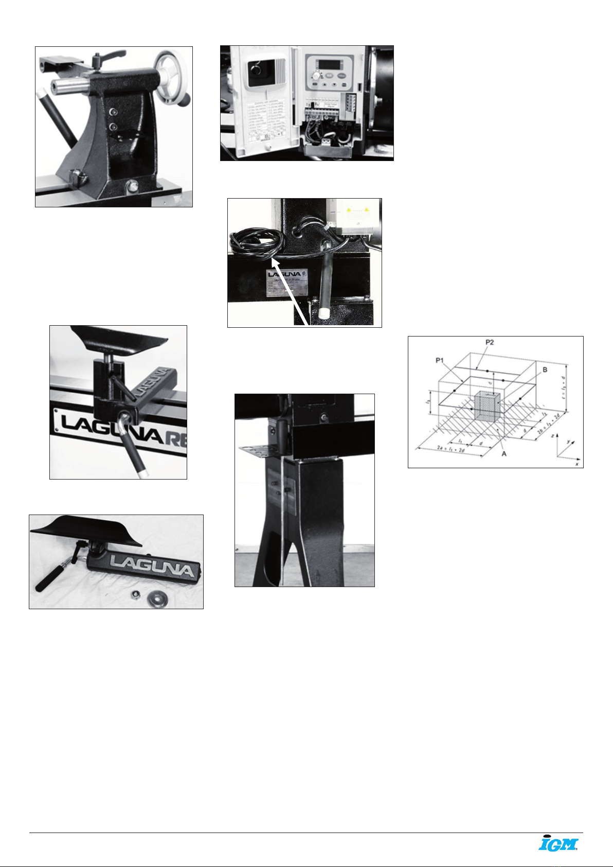
Tail stock
The tail stock is of cast iron construction, and
the spindle has a travel of 4 1/2 in. It can
accommodate centres and other tools which
have a number 2 Morse Taper. The tail stock
can be moved to any position on the lathe bed
and locked to suit the job at hand.
Tail stock viewed from the back.
Pic. 6
EN - English
Operating instructions (Translation of original)
Dear Woodworker,
Thank you for your purchase and welcome to the Laguna Tools group of discerning woodworkers. We understand that you have a
choice of where to purchase your machines and appreciate the condence you have in the Laguna Tools brand.
Every machine manufactured by Laguna Tools has been carefully designed and well thought through from a woodworker’s perspective.
Through hands-on experience, Laguna Tools is constantly working hard to make innovative, precision products. Products that inspire
you to create works of art, are a joy to run and work on, and encourage your performance.
-4-www.igmtools.com
Tail stock viewed from the front
Pic. 7
Tool rest
The tool rest can be moved to any position on
the lathe bed and locked to suit the job at hand.
The tool rest has a tall prole to allow the bowl
turner to turn steep angles. The leading edge
is made from 6 mm hardened steel.
Tool rest assembled to the bed
Pic. 8
Tool rest
Pic. 9
Electrical system
220V: The electrical control system (VFD) is
housed at the back of the head stock, The VFD
converts single phase 220v to three phase.
There is a speed readout at the front of the
lathe with controls to ne adjust the rpm of
the spindle. A power cord with 220V plug is
provided.
Tail stock travel 115 mm
Tail stock removal Self-ejecting
Tail stock taper MK2
Faceplate 76 mm
Bed material Steel
Weight (net/ship) 194 kg / 206 kg
3.3 Noise emissions
Equivalent A-weighted Sound pressure level
according to EN ISO 3746: 75.66 dB(A).
Uncertainty, K in decibels: 4.0 dB (A) according
to EN ISO 4871 The gure quoted is emission
levels and are not necessarily safe working
levels. Whilst there is a correlation between the
emission and exposure levels, this cannot be
used reliably to determine whether or not further
precautions are required. Factors that inuence
the actual level of exposure of the workforce
include characteristics of the work room, the
other sources of noise, etc. i.e. the number of
machines and other adjacent processes. Also
the permissible exposure level can vary from
country to country, This information, however,
will enable the user of the machine to make a
better evaluation of the hazard and risk.
Pic. 13
4. General safety
“WARNING“: For Your Own Safety Read
Instruction Manual before Operating Lathe
4.1 Safety Rules
(a) Wear eye protection.
(b) Do not wear gloves, a necktie, or loose
clothing.
(c) Tighten all locks before operating.
(d) Rotate work piece by hand before applying
power.
(e) Rough out work piece before installing on
faceplate.
(f) Do not mount split work piece or one
containing a knot.
(g) Use lowest speed when starting new work
piece.
• Keep guards in place and in working order.
• Remove adjusting keys and wrenches. Form
habit of checking to see that keys and adjusting
wrenches are removed from tool before turning
it on.
• Keep work area clean. Cluttered areas and
benches invite accidents.
• Don‘t use in a dangerous environment. Don‘t
use power tools in damp or wet locations, or
expose them to rain. Keep work area well
lighted.
VFD with cover open
Pic. 10
Power cord
Pic. 11
Tool storage
A tool storage bracket which can be mounted
on either leg.
Tool storage bracket
Pic. 12
3.2 Technical data
Motor Induction, 1420 rpm, 1,5 kW, S1
Voltage 230V, 50 Hz, 1 Ph.
3 phase output
Recommended breaker size 16 A, tripping
characteristic C (16/1/C).
Swing over bed 457 mm
Swing over banjo 343 mm
Outboard swing max. 813 mm
Distance between centres 914 mm
Floor to spindle centre 1054 mm
Floor to bed height 826 mm
Dim. W x D x H 1524 x 660 x 1194 mm
Tool rest 305 mm
Speed range high: 135 – 3500 rpm
Speed range low: 50 – 1300 rpm
VFD Delta
Spindle M33 x 3.5 mm, righthanded
Spindle taper MK 2
Spindle lock Spring loaded
Spindle indexing 14 / 36 / 48 with lock
Head stock and tail stock bore 9,5 mm

-5-www.igmtools.com
• Keep children away. All visitors should be kept
at a safe distance from the work area.
• Make your workshop kid proof with padlocks,
master switches, or by removing starter keys.
• Don‘t force tool. It will do the job better and
safer at the rate for which it was designed.
• Use right tool. Don‘t force tool or attachment
to do a job for which it was not designed.
• Use proper extension cord. Make sure your
extension cord is in good condition. When using
an extension cord, be sure to use one heavy
enough to carry the current your product will
draw. An undersized cord will cause a drop
in line voltage resulting in loss of power and
overheating.
• Wear proper apparel do not wear loose
clothing, gloves, neckties, rings, bracelets, or
other jewellery which may get caught in moving
parts. Non-slip footwear is recommended. Wear
protective hair covering to contain long hair.
• Always use safety glasses. Also use a face
or dust mask if cutting operation is dusty.
Everyday eyeglasses only have impact resistant
lenses, they are not safety glasses.
• Secure work. Use clamps or a vice to hold the
work when practical. It‘s safer than using your
hand and it frees both hands to operate the tool.
• Don‘t overreach. Keep proper footing and
balance at all times.
• Maintain tools with care. Keep tools sharp
and clean for best and safest performance.
Follow instructions for lubricating and changing
accessories.
• Disconnect tools before servicing and when
changing accessories, such as blades, bits,
cutters, and the like.
• Reduce the risk of unintentional starting. Make
sure power switch is in the off position before
plugging the machine in.
• Use recommended accessories. Consult the
owner‘s manual for recommended accessories.
The use of improper accessories may cause
risk of injury to persons.
• Never stand on tool serious injury could
occur if the tool is tipped or if the cutting tool is
unintentionally contacted.
• Check damaged parts. Before further use of
the tool, a guard or other part that is damaged
should be carefully checked to determine that
it will operate properly and perform its intended
function - check for alignment of moving parts,
binding of moving parts, breakage of parts,
mounting, and any other conditions that may
affect its operation. A guard or other part that
is damaged should be properly repaired or
replaced.
• Direction of feed. Feed work into a blade or
cutter against the direction of rotation of the
blade or cutter only.
• Never leave tool running unattended. Turn
power off. Don‘t leave tool until it comes to a
complete stop.
Location of warning signs
Pic. 14
Locking the lathe
It is strongly recommended that the lathe is
never be left unattended in the unlocked
condition.
To lock the machine it is recommended that a
cover (not supplied) is made to lock the control
panel. We have supplied two concepts for
locking the panel (see below). The cover can
be made from wood or plastic.
First, push down the emergency stop. Then
lock the cover together by putting padlocks [not
included] on the two handles on the control
panel. To safeguard your machine from
unauthorized operation and accidental starting
by young children, the use of padlocks is
strongly recommended.
Pic. 15
Pic. 16
4.2 Electrical connections
Make sure that the power supply meets
the machine‘s requirements (230V). We
recommend using a 16 A breaker, tripping
characteristic C (16/1/C). Note.: Perform
adjustments with the help of a qualied
electrician.
VFD with cover open
Pic. 17
Wooden safety cover Padlocks
Padlocks
Emergency stop switch
Plastic safety cover

-6-www.igmtools.com
Pic. 18
5. Receiving your machine
5.1 Unpacking and transport
To unpack your machine you will need tin snips,
a knife, and a wrench.
1. Using the tin snips, cut the banding that is
securing the packing box (If tted).
Extreme caution must be used, because the
banding will spring and could cause injury.
Lathe in packaging
Pic. 19
Pic. 20
Top packaging removed
Pic. 21
2. Open the box and remove the parts sent with
the lathe including the rst leg.
Note: The legs are heavy and caution must be
exercised. They are cast iron and if dropped
they will break.
3. Remove the top packaging and remove the
second leg.
4. Remove the lathe bed. It is recommended
that it be lifted with a hoist or forklift using a
„sling“ as it is very heavy.
Note: The machine is heavy. Ensure that you
have enough people to do the job safely. Do not
attempt any procedure that you feel is unsafe,
or that you do not have the physical capability
of achieving.
5. Lower the bed of the lathe onto 2 stacks of
wood. This will allow access to the underside of
the bed.
Pic. 22
5.2 Receiving the lathe
Before you unpack your new machine you will
need to rst inspect the packing, invoice and
shipping documents supplied by the driver.
Insure that there is no visible damage to the
packing or the machine. You need to do this
prior to the driver leaving. All damage must be
noted on the delivery documents and signed
by you and the delivery driver. You must then
contact the seller (Laguna Tools) as soon as
practical. If damage is found after delivery,
contact the seller as soon as is practical.
Note: It is probable that you will nd sawdust
within your machine. This is because the
machine has been tested prior to shipment
from the factory. It must be noted that additional
machine movement can take place between
Laguna Tools and the end user and some
adjustments may have to be undertaken by the
customer. These adjustments are covered in
the various sections of this manual.
Parts of the lathe
Supplied with:
Leg Parts
druhá noha
Power
cord
Head stock Tool rest Tailstock and live centre
Tool storage Leg Adjustable feet Leg
Banjo
Pic. 23
Second leg
Tool storage

-7-www.igmtools.com
Pic. 24
Face plate Tool rack Rotating centre Adjustable feet Tail stock bracket
Tool rest comes
fitted to banjo
Removal tool Head stock bracket
Tail stock knob
Drive centre
5.3 Locating your machine
Before you remove your machine from the
packaging, select the area where you will use
your machine. There are no hard and fast rules
for its location, but below are a few guidelines:
1. There should be sufcient area at the front of
the machine to allow you to work on it
comfortably.
2. There should be sufcient area at the back of
the machine to allow access for adjustments
and maintenance to be conducted.
3. Adequate lighting. The better the lighting the
more accurately and safely you will be able to
work.
4. Solid oor. You should select a solid at oor,
preferably one made of concrete or
something similar.
5. Locate it close to a power source and dust
collection.
6. Allow an area for the storage of blanks,
nished products and tools.
6. Assembly and setup
The machine comes mostly assembled. You will
have to assemble the legs, headstock,
tail stock, tool storage and the tool rest to the
bed of the machine.
Note. It is recommended that the head stock,
tool rest and tail stock be removed from the bed
of the lathe to ease assembly
6.1 Assembling legs to the bed of the lathe
There is a stop at both ends of the bed. The
stop is a safety feature that makes it impossible
for the headstock or tail stock to slide off the
end of the bed. Remove the stops and loosen
the clamps on both the head stock, tool rest
and tail stock. Slide them off the bed. This will
greatly reduce the weight of the bed and allow
easier assembly. Note: The headstock and tail
stock are very heavy and extreme caution must
be exercised when removing them from the bed
of the lathe. Take care not to cause damage
during removal.
Pic. 25
Pic. 26
Bed with headstock and tail stock removed
Pic. 27
Pic. 28
Lay the bed on timbers in the upside down
position. Lift the legs to the vertical position and
lower them onto the bed. Secure with the xing
screws provided.
Note: At least two people will be needed to
perform the assembly, one to hold the leg in
position and one to t the xing screws.
Note: If you have any doubt about the
Leg fixing screws Leg
Bed
Tail stock clamp
handle
Knock out rod
-8-www.igmtools.com
Tail stock knob
Pic. 36
Tail stock handle
Pic. 37
6.2 Cleaning the machine
Remove the rust protection grease with
benzine or a similar solvent. It is important that
you remove all the grease and re-lubricate
with a Teon-based lubricant. (Teon has a
lower tendency to attract sawdust and cause
clogging).
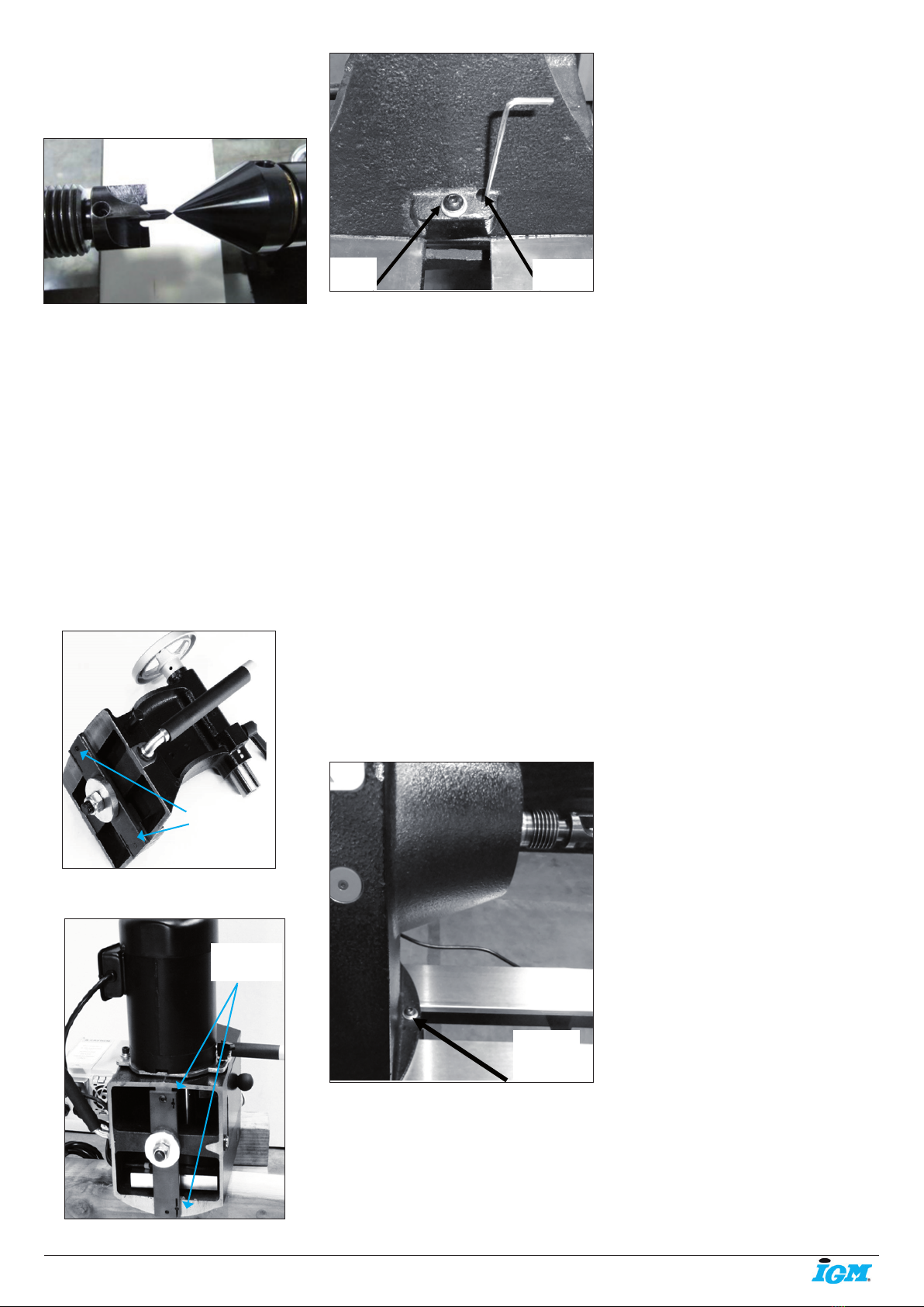
6.3 Fitting the rotating centre
Ensure that the bore of the tail stock is clean.
The rotating centre has a number 2 Morse
Taper that ts into the tail stock. Push the
centre into the tail stock bore rmly, and ensure
that it is securely located. To remove the centre,
rotate the adjusting handle until it is as far back
as possible and this will eject the centre.
Pic. 38
6.4 Fitting the drive centre into head stock
To remove the face plate from the head stock
spindle, insert the removal tool into the hole in
the face plate large diameter. Lock the spindle
with the lathe spindle lock and unlock the face
plate by rotating it. Take care not to drop the
faceplate onto the bed of the lathe.
Note: The face plate has a left-hand thread.
Removal tool
Pic. 39
described procedure, seek professional
assistance. Fit the 4 levelling feet to the lathe
legs with the lock nut on the underside of the
leg. Once both legs have been tted turn the
assembly up to the correct position.
Pic. 29
Pic. 30
Assemble the head stock, tool rest and tail
stock back onto the bed of the lathe and t
the stops.Note: If you have any doubt about
the described procedure, seek professional
assistance. Do not attempt any procedure that
you feel is unsafe, or that you do not have the
physical capability of achieving.
Assembled lathe
Pic. 31
If you decide to t the tool rest after tting the
tail stock, follow the below procedure.
Fit the tool rest onto the bed of the lathe
ensuring that the washer recess ts into the
slot in the bed. Fit the banjo onto the bed with
the bolt through the washer and assemble
the nut onto the thread. Adjust the nut so
that the clamp handle locks the banjo with
approximately 30 degree of movement.
Tool rest disassembled
Pic. 32
Pic. 33
Washer assembled in position
Pic. 34
Pic. 35
Fitting the stock knob
Screw the tail stock knob onto the tail stock
handle.
washer
Tool rest clamp handle
Banjo
clamp
handle
Rotating centre
Adjusting
handle
Levelling foot
-9-www.igmtools.com
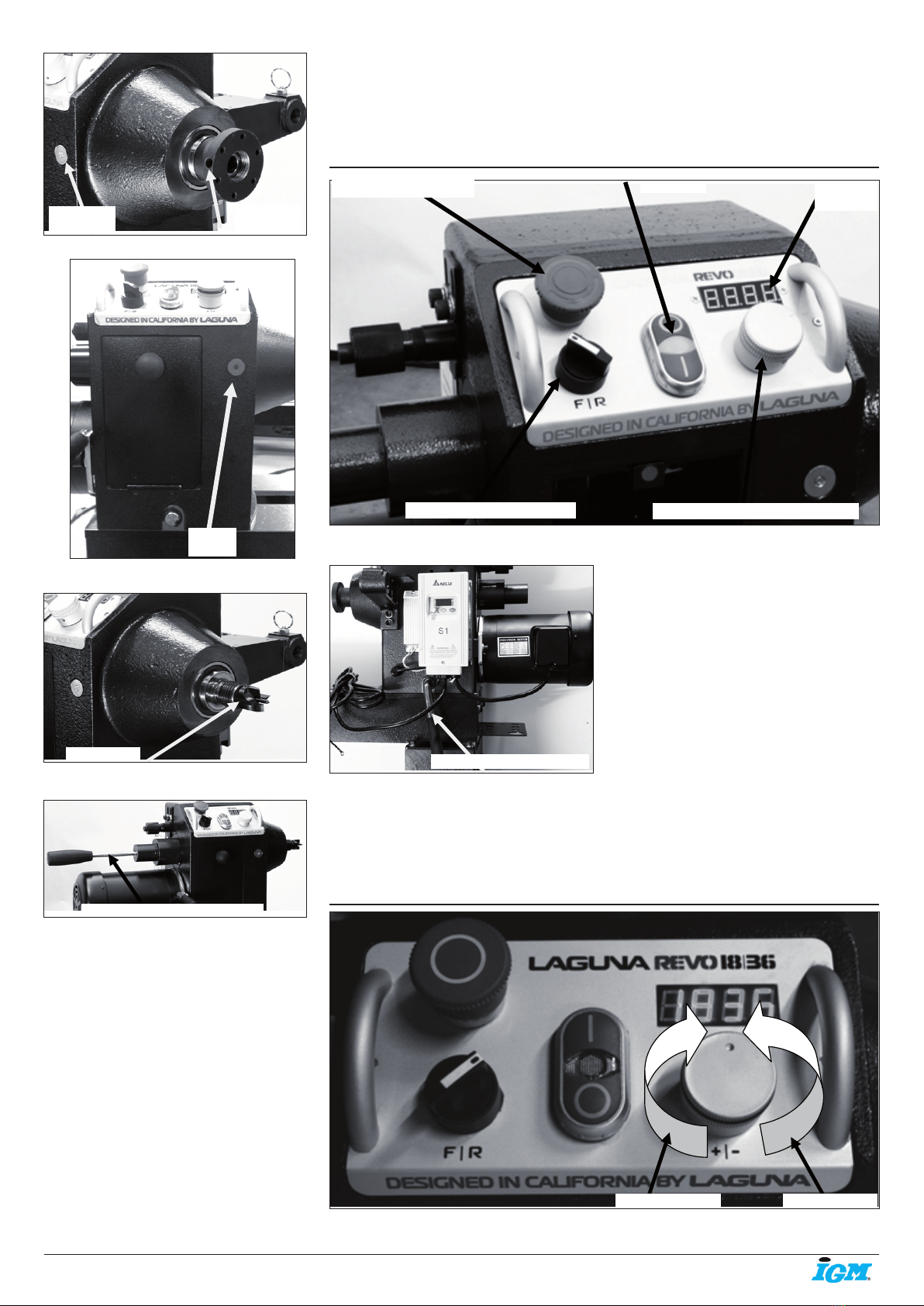
Pic. 45
Head stock clamp lever.
The head stock clamp lever allows the head
stock to be released and moved to any position
on the lathe bed. It is located at the back of the
head stock.
6.7 Variable speed adjustment knob
Pic. 40
Pic. 41
Pic. 42
Pic. 43
Ensure that the bore of the head stock is clean.
The drive centre has a number 2 Morse Taper
that ts into the head stock. Push the centre
into the head stock bore rmly, and ensure that
it is securely located. To remove the centre,
push the rod into the back of the head stock,
and give it a sharp knock. This will remove the
drive centre. Note: Never leave the rod in the
head stock with the machine running.
6.5 Fitting the face plate
Reverse the removal procedure, described
earlier.
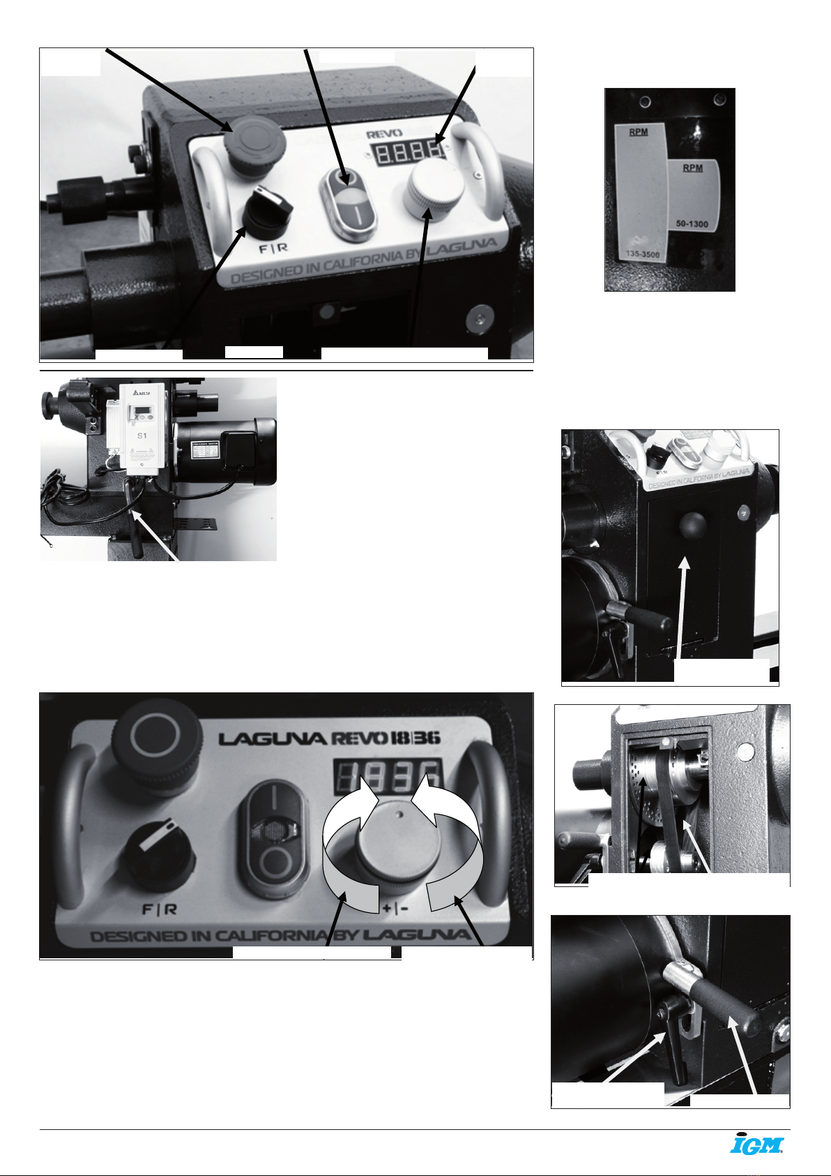
6.6 Lathe controls
Emergency stop button
The emergency stop button will lock in the OFF
position when fully depressed. To reset it, twist
clockwise and it will pop out.
Forward / Reverse switch
The forward / reverse switch selects the
direction of the rotation of the spindle. The
forward / reverse switch must only be used
once the spindle has come to a complete stop.
Start / Stop
The start / stop buttons start the motor and the
rotation of the spindle.
Speed display
The speed display shows the RPM of the
spindle.
Variable speed adjustment knob
The Variable speed adjustment knob adjusts
the spindle speed.
Spindle
lock
Face plate
hole
spindle
lock
Drive centre removal shaft
drive centre
Emergency stop button Start / Stop
Forward / reverse switch
Speed
display
Variable speed adjustment knob
Pic. 44
Pic. 46
Increase speed Decrease speed
Head stock clamp lever

-10-www.igmtools.com
The Variable speed adjustment knob adjusts
the spindle speed. Turns clockwise to increase
the speed, turns counter-clockwise to decrease
the speed.
6.8 High / low speed
The lathe has two sets of pulleys for high
(135 - 3500 rpm) and low (50 - 1300 rpm)
speed ranges.
Adjust between the speed ranges as follows.
1. Disconnect the electric supply to the lathe.
2. Open the pulley cover.
3. Loosen the motor lock handle and lift the
motor to the highest position with the motor
adjustment handle, then lock the motor lock
handle.
4. Move the drive belt to the required set of
pulleys.
High / low speed
Pic. 47
5. Loosen the motor lock handle and with the
motor adjustment handle tension the drive belt,
then lock the motor lock handle. The belt should
be tensioned so that there is approximately 3-6
mm deection when pressed.
Pic. 48
Pic. 49
Pic. 50
6.9 Indexing the spindle
The spindle has 3 sets of indexing holes 14 / 36
/ 48. The selection plunger is located at the
end of the head stock. To move between the 3
sets of holes, loosen the clamp knobs and
slide the indexing plunger assembly to align
with the selected hole set. Clamp in position
with the clamp knobs. Try the plunger in a
few different holes to check that it inserts
and removes smoothly. The indexing plunger
is spring loaded and this is used only to
temporarily align the plunger in the selected
hole. To x the plunger in a selected hole, it
must be attached to the housing by screwing
into the clamped position. There is a hole
selection indicator that allows you to view which
hole in a selected hole set has been selected.
Pic. 51
Pic. 52
Pic. 53
Pic. 54
7. Maintenance
General
Keep your machine clean. At the end of each
day, clean the machine. Wood contains
moisture, and if sawdust or wood chips are not
removed they will cause rust. In general, we
recommend that you only use a Teon-based
lubricant on the lathe. Regular oil attracts dust
and dirt. Teon lubricant tends to dry and has
less of a tendency to accumulate dirt and saw
dust.
Periodically check that all nuts and bolts are
tight.
Drive belt
The drive belt should last for many years
(depending on the usage) but needs to be
inspected regularly for cracks, cuts and general
wear. If damage is found, replace the belt.
Bearings
All bearings are sealed for life and do not
require any maintenance. If a bearing becomes
faulty, replace it.
Rust
The lathe is made from steel and cast iron. All
none-painted surfaces will rust if not protected.
It is recommended that they be protected by
applying wax or a Teon- based lubricant to
them.
Centre point alignment and slide
clearance adjustment
The centre point alignment and slide clearance
are adjusted at the factory and no adjustment
should be required. Should movement or wear
have taken place, the following adjustment
procedure should be conducted. Note: The
Pulley
cover
Pulleys and drive belt
Motor lock handle Motor adjustment
handle
indexing
holes
Clamping
knobs
Hole selection
indicator
Hole
selection
Indexing
plunger
Indexing plunger
engaged
Indexing plunger
disengaged
-11-www.igmtools.com
slide clearance of the headstock and the tail
stock must be checked and adjusted should it
be needed prior to adjusting the centre point
alignment.
Centre points aligned
Pic. 55
Slide adjustment
Loosen the clamp handle on the tail stock and
check for side movement. If it is excessive,
insert an Allen key into the adjusting screw and
tighten.
Note: By rotating the adjustment screw, it
moves into the adjusting slot which opens and
removes the excessive clearance between the
tail stock and the bed.
Note: Only make very small adjustments and
then recheck the clearance. After adjustment
Centre points aligned the tail stock should be
slid along the bed to check for any area that it
binds in the bed slot. The same procedure as
above should be conducted on the head stock
should it be required.
Note: It is very unlikely that the headstock will
require adjustment as it is not moved as often
as the tail stock, so has less tendency‘s for ware.
View under the tail stock
Pic. 56
View under headstock
Pic. 57
Pic. 58
Center point alignment
The tail stock has two clamp screws that are
accessible from the top of the tail stock.
The clamp screws hold the slide plate to the tail
stock casting. There is clearance in the holes
that allows the tail stock to be moved in relation
to the slide plate. The headstock also has two
clamp screws, but one is accessible from under
the headstock.
By loosening the clamp screws the headstock
and tail stock can be moved and the centre
points aligned.
Note: It is recommended that the head stock be
adjusted and not the tail stock. If the tail stock is
not adjusted parallel to the bed slide, the centre
point will not be in alignment when the spindle
is extended or retracted.
1. Loosen the clamp screw that is accessible
from the top on the head stock.
2. Tap the side of the headstock with a rubber
mallet close to the base in the direction
requiring adjustment and retighten the clamp
screw.
3. Recheck the centre point alignment and
repeat if required.
Note: Never hit any part of the lathe that is cast
iron with a metal hammer or similar as it will
break the casting.
Pic. 59
8. Troubleshooting
Lathe will not start
1. Check that the start switch is in the correct
position.
2. Check that the electrical power cord is
plugged into the power outlet.
3. Check that the electrical supply is on (reset
the breaker).
4. With the power disconnected from the
machine, check that the wiring to the plug is
correct. Check that the rubber insulation is
stripped enough and is not causing a bad con-
nection. Check that all the screws are tight.
5. Emergency stop button engaged. Reset
emergency stop button. Twist and it will pop out.
The machine will not stop
This is a very rare occurrence as the machine is
designed to be fail-safe. If it should occur
and you cannot x the fault, seek professional
assistance. The machine must be disconnected
from the power and never run until the fault has
been rectied.
1. The stop switch is faulty. Replace the stop
switch.
Motor tries to start but will not turn
1. With the power disconnected from the
machine, try to turn the spindle by hand. If
the spindle will not turn, check the reason for
jamming.
2. Capacitor faulty. Replace the capacitor.
3. Motor faulty. Replace the motor.
4. Power line overloaded. Correct overloaded
condition.
5. Low voltage. Correct low voltage condition.
Motor overheats
The motor is designed to run hot, but should it
overheat it has an internal thermal overload
protector that will shut it down until the motor
has cooled, and then it will reset automatically.
If the motor overheats, wait until it has cooled
and restart. If the motor shuts down consistently
check for the reason. Typical reasons are dull
cutting tools, the motor cooling fan being
clogged or faulty, the motor cooling ns are
clogged, overfeeding the job, and excessive
ambient temperature.
Squeaking noise
1. Check that the motor cooling fan is not con-
tacting the fan cover.
2. Check the bearings.
3. Check the drive belt is tensioned correctly.
Spindle slows down during a cut
1. Dull cutting tools. Replace the tool or have it
re-sharpened.
2. Feeding the wood too fast. Slow down the
feed rate.
3. Oil or dirt on the drive belt. Clean or replace
the drive belt.
4. Drive belt loose. Re-tension drive belt.
Machine vibrates
1. Machine not level on the oor. Re-level the
machine ensuring that it has no movement.
2. Damaged drive belt. Replace the belt.
3. Job is not balanced. Change to slower speed
and/ or balance the job.
4. Damaged pulley. Replace the pulley.
5. Worn spindle bearing. Replace the bearing.
Adjustment
slots
Clamp
screw
Adjusting
screw
Headstock
clamp
screw
Adjustment
slots

-12-www.igmtools.com
CE-Konformitätserklärung
Produkt: Drechselbank
REVO 1836
Typnummer: MLAREVO 1836
Marke: Laguna
Hersteller:
Laguna Tools Inc
2072 Alton Pkwy, Irvine, CA 92606, USA
Hiermit erklären wir in unserer alleinigen Verantwortung, dass dieses Produkt den folgenden Richtlinien entspricht:
- Maschinenrichtlinie 2006/42/EG
- Niederspannungsrichtlinie 2014/35/EG
- Richtlinie zur elektromagnetischen Verträglichkeit 2014/30/EG
Entworfen in Übereinstimmung mit:
** EN 1870-19:2013
EN60204-1:2006+AC:2010
Technische Dokumentation erstellt von:
TUV Rheinland LGA Products GMBH
Číslo certikátu: BM50418591 & BM50418592
2019-12 Ivo Mlej, CEO
IGM nástroje a stroje s.r.o., Ke kopanině 560, 252 67 Tuchoměřice, Česká republika
-13-www.igmtools.com
Inhaltsverzeichnis
1. Konformitätserklärung
1.1 Gewährleistung
2. Über die Bedienungsanleitung
3. Spezikation der Maschine
3.1 Aufbau der Maschine
3.2 Technische Daten
3.3 Lärmemissionen
4. Allgemeine Arbeitssicherheit
4.1 Sicherheitshinweise
4.2 Stromanschluss
5. Transport und Übernahme
5.1 Transport und Auspackung
5.2 Übernahme der Maschine
5.3 Aufstellung der Drechselbank
6. Zusammenbau der Maschine
6.1 Beine an das Bankbett montieren
6.2 Maschine reinigen
6.3 Pinole installieren
6.4 Führungsspitze in den Spindelstock
installieren
6.5 Planscheibe befestigen
6.6 Drechselbank bedienen
6.7 Geschwindigkeit stufenlos einstellen
6.8 Höhere und niedrigere Drehzahlstufe
6.9 Schritt-Teilung des Spindelstocks
7. Instandhaltung
8. Störungsbehebung
1. Konformitätserklärung
Wir erklären, dass dieses Produkt im
Einklang mit der auf der vorherigen Seite
dieser Gebrauchsanweisung genannten
Richtlinie und Norm.
1.1 Gewährleistung
Die IGM nástroje a stroje s.r.o. strebt
danach, stets ein hochwertiges und
leistungsfähiges Produkt zu liefern. Die
Inanspruchnahme der Gewährleistung richtet
sich nach den jeweils geltenden Geschäfts- und
Gewährleistungsbedingungen der IGM nástroje
a stroje s.r.o.
2. Über die Bedienungsanleitung
Der Zweck dieses Handbuchs ist es,
Einstellungen, Instandhaltung und
Anpassungen Ihrer neuen Maschine zu decken.
Neben allgemeinen Sicherheitshinweisen gilt
dieses Handbuch NICHT für konkrete Holz-
oder Metallbearbeitungstechniken und für die
relevanten Sicherheitsvorkehrungen, die für
konkrete sichere Bedienung erforderlich sind.
3. Spezikation der Maschine
Drechselbänke dienen zur Holzbearbeitung. Auf
einer Drechselbank hergestellte Gegenstände
umfassen Gegenstände wie Möbelbeine,
Lampenständer, Baseballschläger, Schalen
und andere Ziergegenstände. Beim Bearbeiten
des Werkstücks werden die Werkzeugauage,
verschiedene Befestigungswerkzeuge,
Drechselmesser, Meißel und weitere
Werkzeuge gebraucht.
3.1 Bestandteile der Maschine
Die Drechselbank besteht aus einigen
Haupteilen, die in diesem Handbuch
beschrieben sind. Nehmen Sie sich bitte Zeit,
um diesen Teil zu lesen und Ihre Maschine
kennen zu lernen.
Identikation
Auf der Rückseite bendet sich eine Liste
sämtlicher Herstellungsdaten, einschließlich der
Maschinennummer, des Models, usw.
Drechselbankbett
Das Bankbett ist aus vorgeschliffenem
Massivstahl hergestellt.
Abb. 1
Unterer Teil der Drechselbank
Abb. 2
Beine der Drechselbank
Die Beine sind aus Guss hergestellt und
ihre Schwerkonstruktion gewährleistet
gemeinsam mit einem niedrigen Schwerpunkt
die Stabilität der Maschine. Die Beine werden
mit einstellbaren Füßen geleifert, die das
Ausrichten der Maschine auf unebenen
Oberächen ermöglichen.
Zusammengebaute Beine mit einstellbaren
Füßen.
Abb. 3
Spindelstock
Der Spindelstock ist aus Guss hergestellt
es bendet sich darauf eine digitale
Drehzahlanzeige mit Duralumin-Drehzahlregler
und ein Induktionsmotor. Die Spindel kann in
den Positionen nach 14, 36 und 48 arretiert
werden.
Spindelstock von vorne gesehen
Abb. 4
Spindelstock auf dem Maschinenbett
Abb. 5
DE - Deutsch
Bedienungsanleitung (Übersetzung der Originalbedienungsanleitung)
Sehr geehrter Kunde,
Vielen Dank für Ihren Kauf und willkommen in der Familie der Besitzer der Laguna Tools Maschinen von IGM. Wir sind uns dessen
bewusst, dass Sie derzeit auf dem Markt unzählige Marken von Holzbearbeitungsmaschinen nden und wir schätzen es, dass Sie sich
gerade für die Marke Laguna Tools entschieden haben.
Jede Laguna Tools Maschine wurde sorgfältig entworfen, um den Bedürfnissen des Kunden entgegenzukommen. Dank praktischer
Erfahrung arbeitet Laguna Tools ständig daran, innovative Präzisionsprodukte zu schaffen.
Produkte, die Sie zur Schaffung von Kunstwerken inspirieren, Freude an Arbeit bieten und Ihre Leistung unterstützen.

-14-www.igmtools.com
Reitstock
Der Reitstock ist aus Guss hergestellt. Die
Pinolenverstellung beträgt 115 mm. Im
Reitstock kann verschiedenes Zubehör mit
MK2-Befestigung verwendet werden. Der
Reitstock kann in eine beliebige Position auf
dem Bankbett bewegt und entsprechend der
jeweiligen Aufgabe verriegelt werden.
Reitstock von hinten gesehen.
Abb. 6
Reitstock von vorne gesehen.
Abb. 7
Werkzeugauage
Die Werkzeugauage kann in eine beliebige
Position auf dem Bankbett bewegt und
entsprechend der jeweiligen Aufgabe
verriegelt werden. Die Werkzeugauage hat
ein hohes Prol, um Bearbeiten mit steilen
Winkeln, beispielsweise bei Herstellung von
Schüsseln, zu ermöglichen. Die Kante der
Werkzeugauage ist aus gehärtetem Stahl von
6 mm Dicke hergestellt.
Werkzeugauage auf dem Bankbett
Abb. 8
Werkzeugauage
Abb. 9
Elektrisches System
230V: Der Frequenzumrichter für eine
stufenlose Drehzahlregelung bendet sich
auf der Rückseite des Spindelstocks. An der
Vorderseite der Drechselbank bendet sich eine
Geschwindigkeitsanzeige mit Bedienelementen
für Feinabstimmung der Motordrehzahl. Ein
Netzkabel mit einem 220-V-Stecker wird
mitgeliefert.
Frequenzumrichter mit offener Abdeckung
Abb. 10
Netzkabel
Abb. 11
Ablagefach
Das Ablagefach kann an beide Beine montiert
werden.
Ablagefach montiert.
3.2 Technische Daten
Induktionsmotor 1420 U/min., 1,5 kW
Stromversorgung: 230V, 50Hz, 1 Phase
Empfohlener Schutzschalter:
16 A, Abschaltcharakteristik C (16/1/C)
Bearbeitungsdurchmesser über Führungsbahn
457 mm
Bearbeitungsdurchmesser über
Werkzeugauage 343 mm
Bearbeitungsdurchmesser außer Bankbett
813 mm
Spitzenweite: 914 mm
Spitzenhöhe: 1054 mm
Höhe Boden-Bankbett 826 mm
Abmessung L x B x H 1524 x 660 x 1194 mm
Werkzeugauage 305 mm
Höherer Drehzahlbereich: 135 - 3500 U/min.
Niedrigerer Drehzahlbereich: 50 - 1300 U/min
Frequenzumwandler Frequenzumwandler Delta
Spindelstock M33 x 3.5 mm, rechtsdrehend
Spindelstockkegel MK 2
Spindelarretierung Feder
Spindel-Schritt-Teilung 14 / 36 / 48, arretierbar
Spindelstock- und Reitstockbohrung 9,5 mm
Pinolenverstellung 115 mm
Pinolenverstellung Selbstlaufend
Morsenkonus MK2
Planscheibe 76 mm
Bankbett-Material Stahl
Gewicht (Maschine/Transport) 194 kg / 206 kg
3.3 Lärmemissionen
Äquivalenter Schalldruckpegel A gemäß EN
ISO 3746: 75,66 dB (A) Unsicherheit, K in
Dezibel: 4,0 dB (A) gemäß EN ISO 4871.
Die angegebenen Werte sind
Emissionswerte und nicht unbedingt
sichere Arbeitsgeräuschpegel.
Obwohl ein Zusammenhang zwischen
Emissionswerten und Aussetzung besteht,
kann er nicht zuverlässig verwendet
werden, um zu bestimmen, ob zusätzliche
Vorbeugungsmaßnahmen erforderlich
sind oder nicht. Zu den Faktoren, die das
Aussetzungsniveau beeinussen, zählen die
Abmessungen des Arbeitsraums, weitere
Geräuschquellen, usw. D.h. die Anzahl
der Maschinen und weiterer Prozesse. Die
zulässigen Aussetzungsniveaus können von
Land zu Land variieren.
Abb. 13
4. Allgemeine Arbeitssicherheit
Warnung: Lesen Sie die Bedienungsanleitung,
bevor Sie die Maschine starten, um eigene
Sicherheit zu gewährleisten.
4.1 Sicherheitshinweise
(a) Schützen Sie Ihre Augen.
(b) Tragen Sie keine Handschuhe, Krawatten
oder lose Kleidung.
(c) Vor Inbetriebnahme ziehen Sie alle lockeren
Teile fest.
(d) Drehen Sie das Werkstück von Hand, bevor
Sie die Maschine starten.
(e) Bevor Sie das Werkstück an die
Planscheibe befestigten, bearbeiten Sie es.
Abb. 12
-15-www.igmtools.com
(f) Befestigen Sie in die Drechselbank keine
beschädigten Werkstücke oder Werkstücke mit
einem Ast.
(g) Beginnen Sie, mit niedriger Geschwindigkeit
zu arbeiten.
• Alle Sicherheitsabdeckungen in einem
funktionsfähigen Zustand erhalten.
• Werkzeugschlüssel und sonstige
Einstellungswerkzeuge von der Oberäche der
Drechselbank entfernen. Machen Sie sich zur
Gewohnheit, dass Sie stets überprüfen, dass
alle Werkzeuge von der Maschinenoberäche
entfernt sind, bevor Sie die Maschine
einschalten.
• Den Arbeitsbereich sauber halten. Eine
unordentliche Werkstatt oder Unordnung in
der Nähe der Maschine kann zu einem Unfall
führen.
• Nicht in einer gefährlichen Umgebung
verwenden. Verwenden Sie die Maschine oder
Werkzeuge nicht in feuchten oder nassen
Umgebungen und setzen Sie sie keinem Regen
aus. Der Arbeitsbereich muss gut beleuchtet
werden.
• Außerhalb der Reichweite von Kindern
aufbewahren. Unerfahrenes Personal in einem
sicheren Abstand vom Arbeitsbereich halten.
• Sichern Sie die Werkstatt vor Kindern mit
Schlössern, Zentralschaltern oder indem Sie
Startschlüssel sicher lagern.
• Beim Arbeiten keine übermäßige Kraft
verwenden. Die richtige Maschine wird die
Arbeit besser und sicherer ausführen mit
einer Geschwindigkeit oder Kraft, die für die
Maschine vorgesehen sind.
• Richtige Werkzeuge verwenden. Verwenden
Sie Werkzeuge oder Zubehör nicht für Arbeiten,
für die sie nicht bestimmt sind.
• Richtiges Verlängerungskabel verwenden.
Vergewissern Sie sich, dass sich der
Verlängerungskabel in einem guten Zustand
bendet. Wenn Sie ein Verlängerungskabel
verwenden, vergewissern Sie sich, dass es
genügend stark ist. Die Verwendung eines
unrichtigen Verlängerungskabels kann zu
Überhitzung oder Energieverlusten führen.
• Richtige Arbeitskleidung tragen. Tragen
Sie keine losen Kleidungsstücke, Krawatten,
Handschuhe, Armbänder, Ringe oder
anderes Zubehör, das sich in beweglichen
Teilen verfangen kann. Wir empfehlen,
rutschfeste Schuhe zu tragen. Lange Haare
zusammenbinden.
• Augenschutz stets verwenden. Wenn beim
Arbeiten Staub entsteht, verwenden Sie auch
eine Gesichts- oder Staubschutzmaske.
Alltagsbrillen haben nur schlagfeste Gläser; es
handelt sich um keinen sicheren Augenschutz.
• Werkstück stets gegen ungewollte
Bewegung ordnungsmäßig absichern. Wenn
möglich, verwenden Sie Klemmen oder
eine Werkstückspannvorrichtung. Deren
Verwendung ist sicherer, als wenn das
Werkstück von Hand geschoben wird und
darüber hinaus haben Sie beide Hände frei, um
die Maschine zu bedienen.
• Beugen Sie sich nicht über die Maschine.
Halten Sie stets Gleichgewicht beim Arbeiten.
• Führen Sie Wartung regelmäßig durch. Zur
Gewährleistung einer sauberen und sicheren
Arbeit verwenden Sie nur scharfe und saubere
Werkzeuge. Halten Sie Anweisungen für
Abb. 14
Schmieren und Zubehörwartung ein.
• Trennen Sie die Maschine von der
Stromversorgung, bevor Sie Zubehörteile oder
Bauteile der Drechselbank austauschen.
• Risiko eines unabsichtlichen Starts
reduzieren. Vergewissern Sie sich, dass sich
der Ein-/Aus-Schalter in Aus-Position bendet,
bevor Sie die Maschine an Stromversorgung
anschließen.
• Ausschließlich empfohlenes Zubehör
verwenden. Empfohlenes Zubehör nden Sie
im Benutzerhandbuch. Verwendung des nicht
empfohlenen Zubehörs kann zu Verletzungen
von Personen führen.
• Auf die Maschine niemals treten. Die
Drechselbank könnte umkippen.
• Maschinenteile auf Beschädigung
überprüfen. Überprüfen Sie vor jeder
weiteren Verwendung der Maschine
sorgfältig die Schutzvorrichtungen oder
andere Teile, die bei der vorherigen
Verwendung möglicherweise beschädigt
wurden. Überprüfen Sie die Ausrichtung
der beweglichen Teile, ihre Befestigung,
Beschädigung oder andere Bedingungen, die
den Betrieb der Maschine beeinträchtigen
können, um einen ordnungsgemäßen Betrieb
sicherzustellen. Beschädigte Schutzmittel oder
Schutzeinrichtungen sind vor jeder Verwendung
der Maschine ordnungsmäßig zu reparieren
oder auszutauschen.
• Richtung der Werkstoffzuführung. Führen Sie
den Werkstoff stets gegen die Drehrichtung des
Sägebands, Messers oder Fräsers zu.
• Lassen Sie die Maschine niemals
unbeaufsichtigt laufen. Schalten Sie den
Motor aus. Lassen Sie laufende Maschine
nicht alleine, bis sie vollständig zum Stillstand
gekommen ist.
Warnzeichen
Abb. 14
Verriegelung der Drechselbank
Es wird nachdrücklich empfohlen, dass die
Drechselbank niemals unbeaufsichtigt entriegelt
bleibt. Es wird empfohlen, eine verriegelbare
Abdeckung des Kontrollpanels herzustellen.
Des Weiteren werden zwei Möglichkeiten
vorgeschlagen, wie das Kontrollpanel verriegelt
werden kann. Die Abdeckung kann aus
Holz oder aus Kunststoff hergestellt werden.
Drücken Sie zuerst auf die Nothalttaste.
Anschließend sichern Sie die Abdeckung ab,
indem Sie auf beide Griffe des Kontrollpanels
Vorhängeschlösser platzieren (nicht im
Lieferumfang enthalten). Um Ihre Maschine
vor unbefugtem Gebrauch durch Kinder oder
unerfahrenes Personal zu schützen, wird die
Verwendung von Vorhängeschlössern dringend
empfohlen.

-16-www.igmtools.com
Abb. 15
Abb. 16
4.2 Stromanschluss
Versichern Sie sich, dass die Stromversorgung
den Anforderungen der Maschine (230 V)
entspricht.
Es wird empfohlen, den
Leistungsschutzschalter 16A,
Abschaltcharakteristik C, (16/1/C) zu
verwenden.
Anm.: Die Installation muss von einer
qualizierten Elektrofachkraft ausgeführt
werden.
Frequenzumrichter mit offener Abdeckung
Abb. 17
Abb. 18
5. Transport und Übernahme
5.1 Transport und Auspackung
Um die Maschine auszupacken, werden Sie
eine Zange, ein Messer und einen Schlüssel
benötigen.
1. Schneiden Sie mit der Zange das Band, das
die Maschine auf der Palette sichert (soweit
sie auf einer Palette ist). Achtung: Es ist mit
äußerster Vorsicht zu verfahren, denn das
Band ist gespannt und beim Abschneiden kann
es zu Verletzungen kommen.
Verpackte Drechselbank
Abb. 19
Abb. 20
Geöffnete Verpackung
Abb. 21
2. Kiste öffnen und die Teile der Drechselbank
einschließlich des ersten Beins herausnehmen.
Anm.: Seien Sie vorsichtig beim
Herausnehmen, die Beine sind aus Guss
hergestellt und können beschädigt werden,
wenn Sie runterfallen.
3. Den oberen Verpackungsteil mit dem zweiten
Bein herausnehmen.
4. Drechselbankbett herausnehmen. Es wird
empfohlen, es mit einem Hebezeug oder
Gabelstapler mit einer Schlinge anzuheben, da
es sehr schwer ist.
Anm.: Die Maschine ist sehr schwer. Versichern
Sie sich, dass Sie genügend Personen zur
Verfügung haben, um die Drechselbank
zusammenzubauen. Anm.: Soweit Sie Zweifeln
bezüglich des beschriebenen Verfahrens
haben, suchen Sie Fachhilfe aus. Versuchen
Sie kein Verfahren, von dem Sie vermuten,
dass es gefährlich sein könnte oder zu dem Sie
sich nicht genug physisch kompetent fühlen.
5. Das Bankbett auf vorbereitete Unterlagen
(z.B. Holzstücke) setzen. Dadurch erhalten Sie
Zugriff auf die unteren Teile des Bankbetts.
Abb. 22
5.2 Übernahme der Maschine
Sie müssen stets die vom Fahrer
übergegebenen Verpackungs-, Rechnungs-
und Transportdokumente überprüfen, bevor Sie
eine neue Maschine auspacken. Vergewissern
Sie sich, dass die Verpackung oder Maschine
keine sichtbare Beschädigung aufweist.
Überprüfen Sie dies bevor der Fahrer wegfährt.
Sämtliche Schäden sind in Lieferdokumenten
zu vermerken und von Ihnen und dem
Lieferanten zu unterzeichnen. Kontaktieren Sie
den Lieferanten so schnell wie möglich. Wenn
sie eine Beschädigung nach der Anlieferung
entdecken, wenden Sie sich so schnell wie
möglich an Ihren Händler.
Anm.: Es ist wahrscheinlich, dass sich an der
Maschine Sägemehl bendet. Die Maschine
wird getestet, bevor sie ausgeliefert wird. Beim
Versand kann die Maschine bewegen, es ist
deshalb möglich, dass kleine Anpassungen
erforderlich werden. Diese Anpassungen sind
in einzelnen Teilen dieser Bedienungsanleitung
beschrieben.
5.3 Lieferumfang
Mit der Drechselbank geliefert:
Abb. 23
Abb. 24
5.3 Aufstellung der Drechselbank
Wählen Sie den Bereich, wo die Maschine
aufgestellt wird, bevor Sie die Drechselbank
von der Kiste heben. Es gibt keine strikten
Regeln für deren Aufstellung, nachstehend
nden Sie einige Anweisungen.
1. Lassen Sie an der Vorderseite der
Drechselbank genügend Platz, um bequem
arbeiten zu können.
2. Auf der Rückseite der Drechselbank sollte
ausreichend Platz vorhanden sein, um den
Zugang für Einstellungen und Wartungsarbeiten
zu ermöglichen.
3. Genügende Beleuchtung. Je bessere
Beleuchtung, desto genauer und sicherer
können Sie arbeiten.
4. Stabiler und fester Fußboden. Sie sollen
einen festen, ebenen Fußboden wählen, am
besten aus Beton oder ähnlichem Material, um
die Maschine aufzustellen.
5. Drechselbank in der Nähe der
Stromversorgung und Absaugung aufstellen.
6. Um die Drechselbank genügend Platz für
Material, fertige Werkstücke und Werkzeuge
lassen.
6. Zusammenbau der Maschine
Die Maschine wird teilweise zusammengebaut
geliefert. An das Drechselbankbett müsse
Beine, Spindelstock, Reitstock und Ablagefach
montiert werden.
Anm.: Es wird empfohlen, die Werkzeugauage,
den Spindelstock und den Reitstock vom
Bankbett zu entfernen, um den Zusammenbau
zu erleichtern.
6.1 Beine an das Bankbett montieren
An beiden Enden des Bankbetts gibt es
Anschlagplatten. Die Anschlagplatten
verhindern das Runterfallen des Spindelstocks
und des Reitstocks. Anschlagplatten entfernen
und Verriegelung des Spindelstocks, der
Bein Teile der Drechselbank
zweiter Bein
Netzka-
bel
Sicherheitsabdeckung
aus Holz
Vorhän-
geschlö-
sser
Vorhän-
geschlösser
Not-Aus-Schalter
Sicherheitsabdeckung
aus Kunststoff

-17-www.igmtools.com
Planscheibe Ablagefach Pinole einstellbare Füße Werkzeughalter
Unterstützung am Reitstock
Schlüssel der
Planscheibe
Werkzeugauflage
Auswurfstange mit
Messingspitze
Stirnmitnehmer Unterstützung am Spindelstock
Spindelstock Werkzeugauflage Pinolenhalter und Führungsspitze
Ablagefach Bein Rückenleh-
nenhalter
höhenveste-
llbare Füße
Bankbett
Abb. 23
Handauage und des Reitstocks lösen. Vom
Bankbett herausschieben. Dadurch wird das
Gewicht des Bankbetts reduziert, um die Beine
einfacher montieren zu können.
Anm.: Seien Sie vorsichtig beim
Herausschieben des Spindelstocks und des
Reitstocks, beide sind sehr schwer. Bei der
Demontage achten Sie darauf, dass sie nicht
beschädigt werden.

-18-www.igmtools.com
Zerlegte Werkzeugauage
Abb. 32
Abb. 33
Unterlegscheibe im Bankbett
Abb. 34
Abb. 35
Griff des Handrads für Pinolenverstellung.
Den Griff an das Handrad einschrauben.
Abb. 25
Abb. 26
Bankbett ohne Spindelstock und Reitstock
Abb. 27
Abb. 28
Das Bankbett mit der Oberseite nach unten auf
die vorbereiteten Holzunterlagen setzen. Beine
zur Montage an das Bankbett vorbereiten. Mit
den mitgelieferten Schrauben befestigen.
Anm.: Beim Zusammenbau sind mindestens
zwei Personen erforderlich, eine hält das Bein
und die andere zieht die Schrauben an.
Anm.: Soweit Sie Zweifeln bezüglich des
beschriebenen Verfahrens haben, suchen Sie
Fachhilfe aus. Versuchen Sie kein Verfahren,
von dem Sie denken, dass es gefährlich ist
oder zu dem Sie sich nicht genug physisch
kompetent fühlen. Ausrichtfüße an die Beine
der Drechselbank montieren. Nach dem
Zusammenbauen die Drechselbank auf die
Beine setzen.
Abb. 29
Abb. 30
Den Spindelstock, Reitstock und die
Werkzeugauage in das Bankbett zurück
einschieben. Vergessen Sie nicht, auch die
Anschlagplatten zu montieren.
Anm.: Soweit Sie Zweifeln bezüglich des
beschriebenen Verfahrens haben, suchen Sie
Fachhilfe aus. Versuchen Sie kein Verfahren,
von dem Sie vermuten, dass es gefährlich
sein könnte oder zu dem Sie sich nicht genug
physisch kompetent fühlen.
Zusammengebaute Drechselbank
Abb. 31
Sollten Sie sich entscheiden, die
Werkzeugauage zu montieren, erst nachdem
der Reitstock eingeschoben ist, verfahren Sie
nach den Anweisungen unten.
Werkzeugauage mit der Schraube in der
Bankbettführung auf das Bankbett setzen.
Unterlegscheibe und Mutter auf die Schraube
der Werkzeugauage montieren und festziehen.
Mutter festziehen und Werkzeugauage mit
dem Sperrhebel sichern.
Unterlegscheibe
Arretierung der Werkzeugauflage
Sperrhebel
der Werkze-
ugauflage
Höhenverstellbarer Ausgleichfuß
Arretierhebel des
Reitstocks
Schrauben zur
Montage der Füße Bein
Bankbett

-19-www.igmtools.com
Griff des Reitstocks
Abb. 36
Handrad für Pinolenverstellung
Abb. 37
6.2 Maschine reinigen
Rostschutzfett mit Benzin oder einem
ähnlichen Lösungsmittel entfernen. Es ist
wichtig, das gesamte Fett zu entfernen und
anschließend die Maschinenoberäche
mit einem Schmiermittel auf Telon-Basis
zu behandeln (Telon neigt weniger dazu,
Sägemehl anzuziehen und Verstopfungen zu
verursachen).
6.3 Pinole installieren
Vergewissern Sie sich, dass die Bohrung des
Reitstocks sauber ist. Die Pinole hat einen
Morsenkonus MK2. Die Pinole in die Bohrung
des Reitstocks drücken und auf festen Sitz
überprüfen. Um die Pinole vom Reitstock
herauszunehmen, das Handrad drehen, bis sie
locker wird.
Abb. 38
6.4 Führungsspitze in den Spindelstock
installieren
Zur Demontage der Planscheibe vom
Spindelstock sind die mitgelieferten
Demontage-Werkzeuge zu verwenden.
Spindelstock arretieren und Planscheibe
abschrauben. Achten Sie darauf, dass die
Planscheibe nicht auf das Bankbett fällt.
Anm.: Die Planscheibe hat ein
linksdrehendes Gewinde.
Schlüssel zum Lösen der Planscheibe
Abb. 39
Abb. 40
Abb. 41
Abb. 42
Abb. 43
Versichern Sie sich, dass die Bohrung des
Spindelstocks sauber ist. Der Stirnmitnehmer
passt in einen Spindelstockkegel MK2.
Stirnmitnehmer in die Bohrung des
Spindelstocks drücken und auf festen Sitz
Spindelverriege-
lung Bohrung in der
Planscheibe
Spindela-
rretierung
Loch zum Auswerfen des Stirnmitnehmers
Stirnmitnehmer
pinole
Han-
drad
überprüfen.
Um den Stirnmitnehmer auszuschlagen,
verwenden Sie die Auswurfstange und werfen
Sie den Stirnmitnehmer aus.-
Anm.: Schalten Sie die Maschine niemals ein,
wenn sich die Auswurfstange im Spindelstock
bendet.
6.5 Planscheibe befestigen
Das Verfahren zum Entfernen der Planscheibe
in umgekehrter Reihenfolge durchführen.
6.6 Ovládání soustruhu
Not-Aus-Schalter
Der Not-Aus-Schalter rastet in der AUS-Position
ein, wenn er vollständig gedrückt wird. Zum
Zurücksetzen im Uhrzeigersinn drehen.
Drehrichtung der Drechselbank steuern.
Der Vorwärts- / Rückwärtsschalter steuert die
Drehrichtung der Spindel.
Der Vorwärts- / Rückwärtsschalter darf
erst verwendet werden, wenn die Spindel
vollständig zum Stillstand gekommen ist.
Start / Stopp.
Mit den Tasten Start und Stopp wird die
Spindelrotation ein- und ausgeschaltet.
Drehzahlanzeige.
Auf dem Display wird die Drehzahl der Spindel
(U/min.) angezeigt.
Geschwindigkeit stufenlos einstellen.
Mit der stufenlosen Drehzahlregelug wird die
Spindelgeschwindigkeit gesteuert.
-20-www.igmtools.com
Abb. 45
Spindelstock-Klemmhebel.
Mit dem Spindelstock-Klemmhebel wird die
Spindel arretiert oder gelöst und er ermöglicht
ihre Bewegung entlang des Bankbetts. Er ist
auf der Rückseite des Spindelstocks zu nden.
6.7 Geschwindigkeit stufenlos einstellen
Abb. 46
Mit der stufenlosen Drehzahlregelug wird
die Spindelgeschwindigkeit gesteuert.
Durch Drehen im Uhrzeigersinn wird die
Geschwindigkeit erhöht, durch Drehen gegen
Uhrzeigersinn gesunken.
6.8 Höhere und niedrigere Drehzahlstufe
Die Drechselbank verfügt über zwei
Riemenscheiben, für höhere Drehzahlstufe
(135 - 3500 U/min.) und niedrigere.
Riemenscheibe verschieben.
Drehzahlbereiche
Abb. 47
5. Motorverriegelungsgriff lösen und den Motor
mit dem Motoreinstellgriff den Antriebsriemen
spannen, danach den Motorverriegelungsgriff
verriegeln. Der Antriebsriemen sollte so
gespannt sein, dass beim Drücken des
Riemens mit mäßigem Daumendruck eine
Durchbiegung von ca. 3 bis 6 mm (1/8 bis 1/4“)
auftritt.
Abb. 48
Abb. 49
Abb. 50
Riemenscheiben-
-Abdeckung
Riemenscheibe und Antriebsriemen
Motorverriege-
lungsgriff Motoreinstellgriff
NOT-AUS-
-Schalter
Start / Stopp
Drehrichtung
Drehza-
hlanzeige
stufenlose Drehzahlregelung
Abb. 44
Geschwindigkeit erhöhen Geschwindigkeit senken
Drehzahlstufe (50 - 1300 U/min.).
Die Geschwindigkeitsstufe wird wie folgt
geändert:
1. Drechselbank von Stromversorgung trennen.
2. Riemenscheibenabdeckung öffnen.
3. Motorverriegelungsgriff lösen und den
Motor mit dem Motoreinstellgriff in die
höchste Position heben, danach den
Motorverriegelungsgriff verriegeln.
4. Den Antriebsriemen auf die gewünschte
Other manuals for LAGUNA Revo 1836
1
Table of contents
Languages:
Other IGM Lathe manuals


