CHESTER Champion 20VS User manual


1. Safety
1.1 Safety warnings
1.2 Proper use
1.3 Possible dangers caused by the milling machine
1.4 Qualification of personnel
1.5 Safety devices
1.6 Safety check
1.7 Individual protection gear
1.8 For your own safety during operation
1.9 Disconnecting the machine and making it safe
2. Technical Data
3. Assembly
3.1 Extent of supply
3.2 Transport
3.3 Storage
3.4 Installation and assembly
3.5 First use
3.6 Operational accessories
4. Operation
4.1 Safety
4.2 Starting the milling machine
4.3 Inserting tools
4.4 Clamping workpieces
4.5 Changing the speed range
4.6 Selecting the speed
4.7 Manual spindle sleeve feed with the fine feed
4.8 Digital display
4.9 Swiveling the mill-drill head
4.10 Clamping Levers
4.11 End Stops
4.12 Installation on a lathe
5. Maintenance
5.1 Safety
5.2 Inspection and maintenance
5.3 Repair
5.4 Spare parts
5.5 Terminal connecting plan for control system
6. Anomalies
2

1. Safety
This part of the operating manual
•Explains the meaning of use of the warning references contained in the operating
manual
•Explains how to use the machine properly
•Highlights the dangers that might arise for you or others if these instructions are not
obeyed
•Tells you how to avoid dangers
In addition to this manual please observe
•Applicable laws and regulations
•Legal regulations for accident prevention
•The prohibition, warning and mandatory signs as well as the warning notes on the
machine
European standards must be observed during installation, operation, maintenance
and repair of the machine.
If European standards are not applied in the national legislation of the country of
destination, the specific applicable regulations of each country must be observed.
Where necessary, the required measures must be taken to comply with the specific
regulations of each country before the machine is first used.
Always keep this documentation close to the machine.
1.1 Safety warnings
Special Warnings for this Machine
Warning! There is a risk of the machine accidentally restarting after a power failure,
make sure that all of the operation switches are in the off or neutral positions if the
power is interrupted.
Warning! Always wear approved eye protection when operating this machine.
1.2 Proper use
In the event of improper use the machine will
•endanger personnel,
•endanger the machine and other material property of the operator,
•may affect proper operation of the machine
3

This milling machine is designed and manufactured to be used for milling and drilling
cold metals or other non-flammable materials that do not constitute a health hazard by
using commercial milling and drilling tools.
This machine must only be installed and operated in a dry and well-ventilated place.
If the milling machine is used in any way other than described above, modified without
authorization or operated with different process data, then it is being used improperly.
We do not take any liability for damages caused by improper use. Any such
modifications would also render the guarantee null and void.
It is also part of proper use that:
•the maximum values for the machine are complied with
•the operating manual is observed
•inspection and maintenance instructions are observed
1.3 Possible dangers caused by the milling machine
As the machine operates with
•high revolutions
•rotating parts and tools
•electrical voltage and currents
There is a residual risk with use. We have used construction resources and safety
techniques to minimize the risk to health to personnel resulting from these hazards.
We have used construction resources and safety techniques to minimize the risk to
health to personnel resulting from these hazards.
If the machine is used and maintained by personnel who are not duly qualified, there
may be a risk resulting from incorrect or unsuitable maintenance.
All personnel involved in assembly, commissioning, operation and maintenance must
•be duly qualified,
•follow this operating manual
Disconnect the machine whenever cleaning or maintenance work is being carried
out.
Warning!
This machine may only be used with the safety devices activated.
Disconnect the machine immediately whenever you detect a failure in the safety
devices or when they are not fitted. All additional installations carried out by the
operator must incorporate the prescribed safety devices.
4

1.4 Qualification of personnel
This manual is addressed to
•operators,
•users,
•maintenance staff
The warning notes therefore refer to both operation and maintenance of the milling
machine.
Always disconnect the machine plug from the electrical power supply. This will
prevent it from being used by unauthorized personnel.
All personnel involved in assembly, commissioning, operation and maintenance must
•be duly qualified,
•follow this operating manual
In the event of improper use
•there may be a risk to personnel,
•there may be a risk to the machine and other material property,
•the proper operation of the machine may be affected
1.5 Safety devices
Use the milling machine only with properly functioning safety devices.
Stop the machine if there is a failure in the safety device or if it is not functioning for
any reason.
If a device has not been activated or has failed, the milling machine must only be
used when
•the cause of failure has been removed
•it has been verified that there is no resulting danger for personnel or objects
Warning!
If you bypass, remove or override a safety device in any way, you are endangering
yourself any other personnel working with the milling machine. The possible
consequences are
•damage as a result of components or parts of components flying off at high speed.
•contact with rotating parts,
•fatal electrocution
The milling machine includes the following safety devices:
•a self-locking emergency stop button
•a protective cover at the drill-mill head
5

Emergency stop button
The emergency stop button switches the machine off.
Open the cover of the emergency stop button in order to
switch the machine on again.
Protective cover
The drill-mill head is fitted with a protective cover.
Warning!
Remove the protective cover after the mains plug of the machine has been pulled.
1.6 Safety check
Check the milling machine regularly
•at the beginning of each shift,
•once a week,
•after every maintenance and repair operation
General Check
Equipment
Check
OK
Protective covers
Mounted, firmly bolted and not damaged
Labels, markings
Installed and legible
Run Test
Equipment
Check
OK
Emergency Stop
When the Emergency Stop button is activated, the machine
should switch off automatically. A restart will not be possible
until the Emergency Stop button has been unlocked and the
On switch has been activated.
1.7 Individual protection gear
For certain work individual protection gear is required.
Protect your face and eyes. During all work and specifically work during which your
face and eyes are exposed to hazards, a safety helmet with facial protection should
be worn.
Use protective gloves when handling pieces with sharp edges.
Wear safety shoes when you position, dismantle or transport heavy components.
6

Use ear protection if the noise level (inmission) in the workplace exceeds 80 dB (A).
Before starting work, make sure that the prescribed individual protection gear is
available at the workplace.
Caution!
Dirty or contaminated individual protection gear can cause disease. Clean it after
each use and once a week.
1.8 For your own safety during operation
Warning!
Before activating the machine, double check that it will not endanger other people or
cause damage to equipment.
Avoid unsafe working practices:
•The instructions in this manual must be observed during assembly, handling,
maintenance and repair.
•Use protective goggles
•Turn off the machine before measuring the workpiece.
•Do not work on the machine if your concentration is reduced, for example, because
you are taking medication.
•Stay on the machine until all rotating parts have come to a halt.
•Use the prescribed protection gear. Make sure to wear a well-fitting work suit and a
hairnet, if necessary.
•Do not use protective gloves during drilling or milling work.
•Unplug the shockproof plug from the mains before changing the tool.
•Use suitable devices to remove drilling and milling chips.
•Make sure your work does not endanger anyone.
•Clamp the workpiece tightly before activating the machine.
In the description of work on the drilling-milling machine we highlight the dangers
specific to that work.
1.9 Disconnecting the machine and making it safe
Pull the main plug before beginning any maintenance or repair work.
Warning!
Use of unstable lifting equipment and load-suspension devices that break under load
can cause very serious injuries or even death.
Check that the lifting equipment and load-suspension devices are of sufficient load
capacity and in perfect condition.
7

Observe the rules for preventing accidents issued by your association for the
prevention of occupational accidents and safety in the workplace or other inspection
authorities.
Tighten loads properly.
Never walk under suspended loads!
8

2. Technical Data
The following information gives the dimensions and weight and is the manufacturer’s
authorized machine data.
Engine power consumption
750W/240V/50Hz
Drilling capacity
16mm
Face milling capacity
63mm
End milling capacity
20mm
Working radius
185mm
Spindle taper
MT2
Spindle stroke
42mm
T-slot size
12mm
Headstock tilt
±90º
Cross travel
160mm
Longitudinal travel
660mm
Vertical travel
290mm
Dimensions
960 x 570 x 970mm
Net weight
113kg
Emissions
The noise level (emission) of the drilling-milling machine ranges below 78 dB(A). If
the drilling-milling machine is installed in an area where various machines are in
operation, the acoustic influence (inmission) on the user of the drilling-milling
machine may exceed 85 dB(A) in the working area.
We recommend the use of soundproofing and ear protection. Remember that the
duration of the noise pollution, the type and characteristics of the work area and
operation of other machines influence the noise level in the working area.
9

3. Assembly and Connection
The drilling-milling machine comes pre-assembled.
3.1 Extent of supply
When the drilling-milling machine is delivered, check immediately that the machine
has not been damaged during transport and that all components are included. Also
check that no fastening screws have come loose.
Compare the parts supplied with the information on the packaging list.
3.2 Transport
Warning!
Machine parts falling off forklift trucks or other transport vehicles could cause very
serious or even fata injuries. Follow the instructions and information on the transport
case:
•Centers of gravity,
•Suspension points,
•Weights,
•Means of transport to be used,
•Prescribed shipping position.
Use of unstable lifting equipment and load-suspension devices that break under load
can cause very serious injury or even death.
Check that the lifting and load-suspension gear has sufficient load capacity and that
it is in perfect condition.
Observe the rules for preventing accidents.
Holds the load properly.
Never walk under suspended loads.
3.3 Storage
Improper storage may cause important parts to be damaged or destroyed.
Store packed or unpacked parts only under the intended environmental conditions.
Consult Chester UK if the machine or accessories have to be stored for a period of
over three months or under different environmental conditions than those given here.
3.4 Installation and assembly
The work area for operation, maintenance and repair work must not be hindered.
The mains plug of the drilling-milling machine must be freely accessible.
10

Proceed with extreme caution when lifting, installing and assembling the machine.
Danger of crushing and overturning.
•Secure the load-suspension device around the drill-mill head. Use a lifting sling for
this purpose.
•Clamp all the clamping levers at the machine before lifting it.
•Make sure that no add-on pieces or varnished parts are damaged due to the load-
suspension.
•Check the horizontal orientation of the base of the machine with a spirit level.
•Check that the foundation has sufficient floor-load capacity and rigidity.
Insufficient rigidity of the foundation leads to the superposition of vibrations between
the drilling-milling machine and the foundation (natural frequency of components).
Insufficient rigidity of the entire milling machine assembly also rapidly causes the
machine to reach critical speeds, with unpleasant vibrations, leading to bad milling
results.
•Position the drilling-milling machine on the intended foundation.
•Attach the drilling-milling machine using the provided recesses in the machine base.
11

3.5 First use
Cleaning and lubricating.
Remove the anticorrosive agent applied on the drilling-milling machine for transport
and storage purposes. We recommend the use of kerosene.
Do not use any solvents, thinners or other cleaning agents which could corrode the
varnish on the drilling-milling machine. Follow the specifications of the manufacturer
of the cleaning agent.
•Lubricate all bright machine parts with non-corrosive lubricating oil
•Grease the machine according to the lubrication chart
•Check smooth running of all spindles. The spindle nuts can be readjusted.
•Check the fuse protection of your power supply against the technical data for the total
connection value of the machine.
12

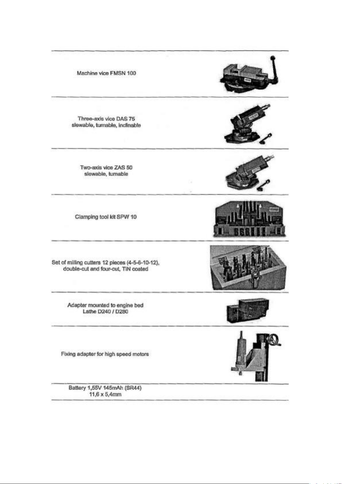
3.6 Optional accessories
13
14
4. Operation
4.1 Safety
Use the drilling-milling machine only under the following conditions.
• The machine is in proper working order
• The machine is used as prescribed
• The operating manual is followed
• All safety devices are installed and activated
All anomalies should be eliminated immediately. Stop the drilling-milling machine
immediately in the event of any anomaly in operation and make sure it cannot be
started up accidentally or without authorization.
4.2 Starting the milling machine
Wait until the machine has come to a complete halt before inverting the turning
direction using the change-over switch.
The speed of the spindle is a little smaller in left-
handed motion than in right-handed motion.
• The rotating direction of the milling machine is
selected using the change-over switch.
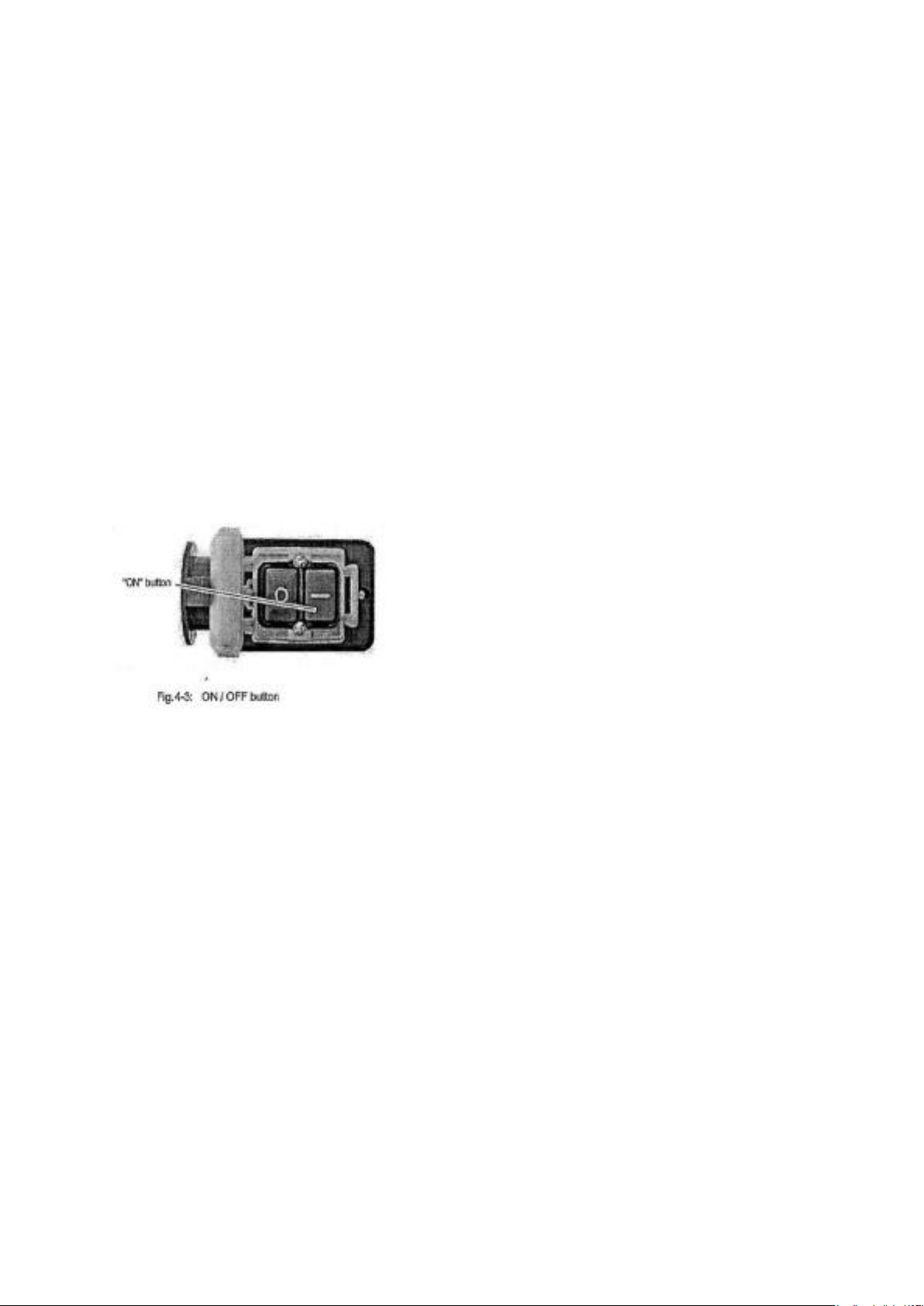
• Press the ON button. The milling machine will
be activated and turn in the pre-selected rotating
direction.
Turning on the machine
Turn the change-over switch into the ‘0’position.
4.3 Inserting tools
When milling operations are performed the cone seat must always be fixed to the
draw-in rod.
All cone connections with the taper bore of the work spindle without using the draw-
in rod is not allowed for milling operations. The cone connector should be released
by the lateral pressure. Injuries by parts flying off.
In the work spindle you may only use tool holding fixtures and clamping tools with
morse taper MK2 and internal screw thread M10 for an interlocking fixture. Reducing
bushes is not allowed.
The mill head is equipped with an MT2 seat and a M10 draw-in rod.
15
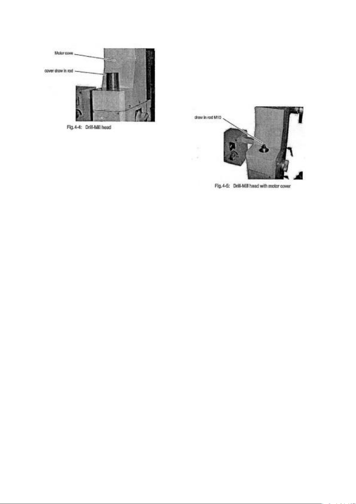
• Remove the cover. There is no need to
disassemble the motor cover completely
• Clean the conical holding fixture in the mill
head.
• Clean the taper of your tool
• Insert the tool into the tool holding fixture
• Screw the draw-in rod into the taper of
your tool.
• Tighten the draw-in nut and fix the spindle.
Use a wrench to hold the spindle
Removing a tool
• Hold the spindle with the wrench and loosen the draw-in rod. Turn the draw-in rod
further so that the tool from the cone admission is squeezed out.
Use of collet chucks
When using collet chucks for the reception of milling tools, a higher operation
tolerance is possible. The exchange of the collet chucks for a smaller or larger end
mill cutter is performed simply and rapidly and the disassembly of the complete tool
is not required.
The work spindle is equipped with a surface for the hold-up with a fork wrench to
unfasten the swivel nut of the collet chuck retainer. The collet chuck is pressed into
the ring of the swivel nut and must hold there by itself. By fastening the swivel nut on
the tool the milling cutter is clamped.
Make sure that the correct collet chuck is used for each milling cutter diameter, so
that the milling cutter may be fastened securely and firmly.
4.4 Clamping workpieces
Tools or collet chucks with a MT2 shank may be clamped directly into the work
spindle. For mounting these tools, proceed as described in ‘inserting tool’ above.
Make sure that the tool is clamped with the draw-in rod.
The workpiece is always to be fixed by a machine vice, jaw chuck or other
appropriate clamping tool.
16

4.6 Changing the speed range
Wait until the machine has come to a complete halt before changing the speed using
the gear switch.
• Turn the gear switch in the position ‘H’ for a speed range of 200 – 3000 min
• Turn the gear switch into the position ‘L’ for a speed range of 100 – 1500 min
• Adjust the speed with the potentiometer. The speed and the cutting speed depends
on the material of the workpiece, the milling cutter diameter and the cutting type.
The electronics controls the rotation speed slowly with a ramp to the set point.
Therefore, wait briefly before you continue with feed motion while milling or drilling.
4.6 Selecting the speed
For milling operations, the essential factor is the selection of the correct speed. The
speed determines the cutting speed of the cutting edges which cut the material. By
selecting the correct cutting speed, the service life of the tool is increased and the
working result is optimized.
The optimum cutting speed mainly depends on the material and on the material of
the tool. With tools (milling cutters) made of hard metal or ceramic insert it is possible
to work with higher speeds than with tools made of high-alloy high speed steel
(HSS). You will achieve the correct cutting speed by selecting the correct speed.
For the correct cutting speed for your tool and for the material to be cut you may
refer to the following standard values or a table reference book.
The required speed is calculated as follows:
17

Standard values for cutting speeds
[m/min] with high speed steel and hard metal in conventional milling.
Tool
Steel
Gray cast iron
Age-hardened
Al Alloy
Peripheral and side milling cutters
10-25mm
10-22mm
150-350mm
Relived form cutters
15-24mm
10-20mm
150-250mm
Inserted tooth cutter with SS
15-30mm
12-25mm
200-300mm
Inserted tooth cutter with HM
100-200mm
30-100mm
300-400mm
The results are in the following standard values for speeds in dependence of the
milling cutter diameter, cutter type and material.
Tool diameter
Peripheral and side
milling cutters
Steel
10-25m/min
Grey cast iron
10-22m/min
Age hardened Al
Alloy 150-250 m/min
35mm
91-227
91-200
1365-3185
40mm
80-199
80-175
1195-2790
45mm
71-177
71-156
1062-2470
50mm
64-159
64-140
955-2230
55mm
58-145
58-127
870-2027
60mm
53-133
53-117
795-1860
65mm
49-122
49-108
735-1715
Tool diameter
Form cutters
Steel
15-24m/min
Grey cast iron
10-20m/min
Age-hardened
Al Alloy
150-250m/min
4mm
1194-1911
796-1592
11900-19000
5mm
955-1529
637-1274
9550-15900
6mm
796-1274
531-1062
7900-13200
8mm
597-955
398-796
5900-9900
10mm
478-764
318-637
4700-7900
12mm
398-637
265-531
3900-6600
14mm
341-546
227-455
3400-5600
16mm
299-478
199-398
2900-4900
Friction during the cutting process causes high temperatures at the cutting edge of
the tool. The tool should be cooled during the milling process. Cooling the tool with a
suitable cooling lubricant ensures better working results and a longer edge life of the
cutting tool.
Use a water soluble and non-pollutant emulsion as a cooling agent. This can be
acquired from authorized distributors.
18
Tool diameter
peripheral and side
milling cutters
Steel
10-25m/min
Grey cast iron
10-22m/min
Age hardened
Al Alloy 150-
350m/min
35mm
91-227
91-200
1365-3185
40mm
80-199
80-175
1195-2790
45mm
71-177
71-156
1062-2470
50mm
64-159
64-140
955-2230
55mm
58-145
58-127
870-2027
60mm
53-133
53-117
795-1860
65mm
49-122
49-108
735-1715

Make sure that the cooling agent is properly retrieved. Respect the environment
when disposing of any lubricants and cooling agents. Follow the manufacturer’s
disposal instructions.
4.7 Manual spindle sleeve feed with the fine feed
Turn the handle screw. The spindle sleeve lever will move towards the drill-mill head
and will activate the clutch of the fine feed.
Turn the spindle sleeve fine feed in order to move the spindle sleeve.
4.8 Digital display
Display for spindle sleeve travel.
Measuring range
mm
0-999.99
inch
0-39.371”
Reading precision
mm
0.01
inch
0.0004”
Power supply (battery)
Round cell 1.55V
145mAh (SR44)
11.6 x 5.4mm
• ON / O switches the display on and resets the reading of the display to “0”
• mm / in converts the measuring unit from millimeters to inches and viceversa
• OFF switches the display off
• ↑ performs a value increase
• ↓performs a value decrease
4.9 Swiveling the mill-drill head
Manual spindle sleeve feed with the fine feed
The clutch of the fine feed has to be disengaged before the spindle sleeve lever can be
used. Activating the spindle sleeve lever when the fine feed is engaged may damage the
clutch.
Loosen the handle screw. The spindle lever moves away from the drill-mill head and
disengages the clutch of the fine feed.
The mill-drill head may be swiveled to the left.
Caution!
The drill head may tilt to the right or the left on it’s own after loosening a screw.
Proceed with extreme caution when loosening the clamping joints.
19
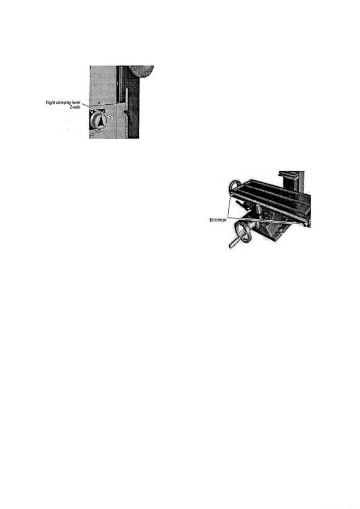
4.10 Clamping Levers
The machine is equipped with clamping levers
for the Z-Axis movement of the drill-mill head
and two clamping levers for the X and Y-Axis
movement of the cross table.
The spindle sleeve is fitted with a clamping
lever.
Use the clamping levers to lock the position of
the axes during milling or drilling operations.
4.11 End stops
The cross table is fitted with two adjustable end
stops on the X-Axis.
Use the end stops for limiting the travel
alongside the X-Axis in order to guarantee the
exact repeatability when manufacturing various
identical components.
4.12 Installation on a lathe
The mill head with column can be mounted on a lathe. For fastening an adapter is
required. The adapter needs to be fixed to the engine bed. It is not possible to fix it to
the lathe slide. The adapter is dimensioned in a way that the middle of the lathe
chuck should be reached with the center of the milling spindle (alignment headstock
– lathe chuck).
Due to the manufacturing tolerances of castings and the manufacturing tolerances of
two different machines it is however not possible to reach the exact center, the
adapter may be too long or short.
If required, the adapter is to be milled off or equipped with dummy sheets. When
using sheets the complete surface is to be filled.
In order to reduce the support expenditure of the column with milling head during the
orientation we recommend you disassemble the milling head off the column.
Unscrew the locking screw (safety screw) position 266. Disassemble the milling head
off the column by completely loosening the clamping screw and the lead screw and
stripping off the milling head.
Control the orientation (90° angle horizonal and vertical) of the column with the
reference planes on the engine bed of the lathe.
20
Table of contents


