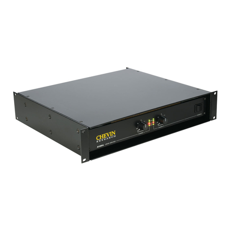
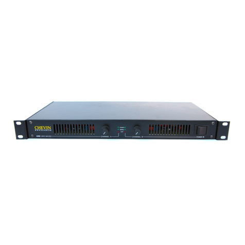
Chevin Research S120L User manual

USER MANUAL
S120L
PROFESSIONAL POWER AMPLIFIER
Chevin Research, Kreuzbichlstraße 29 A-6112 Wattens, Austria
Tel/Fax: +43 (0)5224 51398
www.chevin-research.com
Contents
Important safety instructions ..............
Introduction.........................................
Distributed sound System ..................
Installation and use.............................
Front panel .........................................
Rear panel .........................................
Connection example ..........................
Technical specifications .....................
2
3
3
5
6
6
7
8
Important Safety Instructions
On no account remove the cover. No user serviceable parts inside.
Refer servicing to qualified service personnel.
The lighting flash with arrow symbol within the triangle is intended to alert the user
to the presence of dangerous voltages that may be of sufficient magnitude to constitute a risk of
electric shock.
The exclamation point within the triangle is intended to alert the user to the
presence of important operating and servicing instructions in the literature accompanying the
product.
WARNING - When using electric products basic precautions should always be followed,
including the following:
-Read all these instructions before using the product.
-Do not use the product near water e.g. near swimming pool, kitchen sink, bathtub, or in
a wet basement, etc.
-This product, either alone or in combination with other sound equipments, is capable of
producing sound levels that can cause permanent hearing loss. Do not operate the
product for a long time at high volume level.
1 2

-The product should be located away from heat sources such as direct sunlight and
other sources of heat.
-The product should be connected to a power supply only of the type marked on the rear
panel of the product.
-The power supply cord of the product should be unplugged from the mains socket when
left unused.
-Avoid allowing any objects to enter inside the product or spilling any liquid into it.
-The product should not be used when:
1. The power supply cord or plug has been damaged
2. Objects have fallen or liquid has been spilled into the product
3. The product has been exposed to rain
4. The product does not appear to operate normally or exhibits a marked change in
performance
5. The product has been fallen or enclosure has been damaged
-Do not attempt to service the product. Refer servicing to qualified personnel.
The symbol of crossed-out wheeled bin is intended to inform the user that the
product is the subject to the requirements of the WEEE Directive of the European Parliament.
I.e. after the end of its lifetime the product should not be disposed as unsorted municipal waste
but should be collected separately.
Introduction
This 1-channel professional power amplifier provides high-value performance and
is intended to be used in so-called distributed sound systems.
The designed circuitry provides excellent sound quality and the steel chassis offers maximum
sturdiness. The amplifier can be used in standard 19“ rack mounting or separately.
The amplifier is equipped with LED display system, which provides information on amplifier
status in any lighting condition.
The connection system consists of XLR and RCA connectors for audio input and terminal block
for 50/70/100V output.
Distributed Sound System
Distributed sound systems or constant voltage systems are the most economical way to create
multi-speaker sound systems. A distributed sound system is commonly used for public places
such as schools, factories, hotels, stores, places of worship, etc.
In Europe is usual to have 100V system whereas in the USA 70V systems are usual. These
values relate to the maximum output voltage of the amplifier.
The main difference to a regular low-impedance system (4 or 8 Ohms) is the way of connecting
individual loudspeakers to the loudspeaker line. Many loudspeakers, each equipped with
a transformer, can be connected to one single output line. All of these loudspeakers have the
same input signal and are driven by one amplifier.
It is possible to use as many speakers as it is necessary as long as their total wattage does not
exceed maximum power of the amplifier. Speakers can be freely added or removed from the line
without affecting the levels of other speakers.
Each speaker’s transformer has relatively high impedance at the primary side to connect to the
100V (70V) line. The secondary side matches to the speaker itself (mostly 8 or 4 Ohm).
Depending on the maximum power of an amplifier each 100V (70V) amplifier matches to a
certain minimum impedance than can be connected to this output. It does not matter how this
impedance is achieved. We can use a large number of smaller speakers (with higher impedance
at their transformers) or a small number of larger speakers (with lower impedance at their
transformers) or any combination of them. The only rule is that the total impedance of the 100V
(70V) line should not fall below the minimum impedance of the amplifier's 100V (70V) output.
The regular signal (voltage) during the transmission of music or speech is mostly far less that the
maximum 100V (70V). The voltage in the line changes proportionally in the same way as the
voltage at the audio input of the amplifier, because the output voltage of an amplifier is
determined by the input signal only.
3
4

Installation and Use
ATTENTION!!
Do not open the amplifier – all user-adjustable parts are external - refer servicing to
qualified personnel!
If replacing the fuse is necessary use only the same type and rating!
Do not expose the amplifier to rain or moisture!
This manual contains important information for correct and safe use. Read it carefully before
using the amplifier. Keep it for future consultation.
Connection to the mains supply
Before connecting the amplifier to the mains socket always make sure that:
-The electric system and mains socket have an adequate grounding – compatible with
the safety regulations for your country (If you are uncertain consult specialized
personnel);
-The mains voltage corresponds to that shown on the rear panel (accepted allowance is
up to +/-10%);
-Power cord is not damaged and has no bare wires;
-The on/off switch is in the off position.
Also make sure that the amplifier is off before disconnecting the power cord from the mains
socket.
Switching on and off
In your sound reinforcement system always switch on the amplifier after all the other
equipment and always switch it off before, if possible with gain control set at minimum – this
will avoid dangerous signal peaks.
Installation
The amplifier can be used in 19” rack mounting or separately.
Do not expose the amplifier to direct sunlight or any source of heat or rain.
Do not cover the amplifier during its operation.
All of these actions can cause faulty operation or even electric shock or fire.
Audio Connections
Always use good quality cables of the appropriate type.
Take care of cables and check their condition frequently. Grip them by the connector, do not pull
them forcefully and wind them without knots and sharp bends.
Front Panel
12 33
1. Power switch - used for turning on or off the amplifier
2. Gain control
3. LED indicators:
Green light of ON indicator indicates that the amplifier is on, no matter if there is any
input signal.
Green SIGNAL LED indicates the presence of the signal.
Red CLIP LED indicates clipping (=flattening the peaks of the waveform) of the
amplifier, i. e. that audio signal level exceeds the capacity of the amplifier channel. In
this case reduce the input signal level until the CLIP LED goes out..
Rear Panel
653421
1. Power mains cord
2. Mains fuse
3. Balanced INPUT connector
Input female XLR connector can receive balanced or unbalanced signal.
Note: Prefer using balanced cable; they are less prone to AC hum. Avoid mixing
balanced and unbalanced cables for one sound system as even one unbalanced cable
can unbalance the whole system and cause hum.
4. Unbalanced INPUT connector
RCA connectors
Note: It is possible to use balanced and unbalanced INPUT at the same time. Then
output signal is powered mix of both INPUTs. In this case the amplifier works as a
mixer.
5. SEND connector
Input male XLR connector also can receive balanced or unbalanced signal.
Balanced INPUT and SEND connectors are connected in parallel. The same signal that
is present at the INPUT connector is present at the SEND connector.
6. OUTPUT connector
Terminal block is used for output signal. You can use 100V or 70V or 50V output.
5 6

Connection Example
By using the S120L amplifier it is possible to create one loudspeaker line with a maximum of
120W/100V (or 120W/70V or 120W/50V) connected at the output. All of these loudspeakers
have the same input signal and are identically driven by the amplifier.
If necessary, the signal connected to balanced INPUT of the amplifier can be sent through the
SEND connector to other amplifiers.
This manual is intended for informational purposes only. All details included herein are subject to change without notice. Chevin Research shall
not be held responible for any damages, direct or indirect, arising from or relating to the use of this manual.
© Chevin Research 2008. All rights reserved.
Technical Specifications
Power output (1kHz, 1% THD) 120 W
Input sensitivity 1V
Input impedance 20kOhm balanced
THD (1kHz, -3dB) < 0,05%
Frequency response (-3dB) 20 Hz – 20 kHz
Signal/noise ratio
20 Hz – 20 kHz below rated power
“A” weighted
> 95 dB
> 98 dB
Output 100V / 70V / 50V
Protection Limiter peak signal
Short circuit protection
Thermal protection
Over-current protection
Load mismatch protection
Cooling convection
Connections
Input
Output
Balanced male XLR + female XLR
Terminal block
Controls Power switch + gain control
Indicators Green LED – ON, SIGNAL
Red LED – PEAK
Power requirements AC 220-240V / 50-60Hz
Dimensions 483 x 44 x 293 mm / rack 1U
Weight 6 kg
7
8
Table of contents
Other Chevin Research Amplifier manuals
